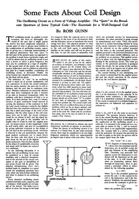
Some Facts About Coil DesignThe Oscillating Circuit as a Form of Voltage AmplifierThe "Qain"in the <strong>Broadcast</strong>Spectrum of Some Typical Coils The Essentials for a Well-Designed CoilBy ROSS GUNNTHE oscillating circuit, as applied to radio of a magnetic field, the capacity serves to store when one potential reaches its instantaneousreception, has been so thoroughly discussedin the past that itthe energy in the form of an electrostatic field, maximum, the other potential isgoing throughmight appear and the resistance serves to transform this stored its instantaneous zero value. These two potentialshave a certain interesting relation in termscertain point of view is always most fruitful in happens as the energy shifts from the condenser of the circuit constants. One of these potential?the matter has been completely exhausted. A energy into heat. The physical picture of whatthe consideration of oscillating circuits, especiallyin giving one a thorough understanding of familiar to the reader, and will not be given at and the other as the generated potential. Theto the coil, and back again, is undoubtedly will be referred to as the applied potentialthe physical phenomena that take place. In this time. In case the reader is unfamiliar with applied potential is the potential introduced intothe first part of the present paper an approach tothe circuit from some outside influence, such asthe problem is made from a particular angle, andan oscillator or an antenna. This applied potentialisit will be shown that an oscillating circuit is notD OSS GUNN,only a device to select a given frequency butthe author of this in phase with the high-frequency currentarticle,*may also be considered which is the first of two on as a type of the flowingsubjectin the oscillating circuit. The other potential,or the generated potential, is producedamplifier.of receivingIn the second part of the paper, the set radio-frequencyinductance and research within the its relation to engineer for the United States Aircircuit, by the action of the oscillat-inductors, was formerly a radioselectivity Service. Mr. Gunn is now attached to the Shane ing current, and is 90 degrees out of phase withand gain in a tuned amplifier, considering theLaboratoryoscillating circuit, is discussed. Finally, theat Yale the current and theUniversity and has devotedapplied potential.Theconsiderable attention toprime factors that should be considered to makethe currentproblems invokedflowing in any alternating currentcircuit is determined byinup the the ideal coil are design and use of coils in high-frequencythe applied potentialand the circuitgiven.oscillatingThe resistance or "loss" in an circuits. The present article doesconstants, in the mannernotoscillatingcircuit is made up of several components, and pretend to be revolutionary, for the basic given by the well known equation:theoryinvolved is atit is convenient to divide the circuit resistanceleast 50 years old. The author,instead of discussing power factor and= 1decrement,which have littleinto two parts, namely, the part due to coil resistance,and the part due to condenser to many read-resis-meaningers, has chosen to use atance. Modern factor which has a simplecondensers are relatively efficientsince they have resistances of only a fraction physical interpretation. The idea that there are where I is the current, Ea is the applied potential,L is the inductance, C the capacity, R thetwo potentials in anof an ohm oscillating circuit and thatat broadcast frequencies, while theordinary coils have resistances of from 5 to their ratio is the power factor, is of course well50equivalentknown, but the useohms. It is then obvious that, even if a manufacturerof the bestof the factor "G" series resistance, f the frequency,to explain and it is a numerical constant of value 3.1416.good condensers would succeed ratio of inductance to capacity, has If the circuit is resonated to ainrarely been pointed out. The definite frequency,casual reader willcutting the resistance of his condenserthe reactances arein balanced andhalf,equation (i)findthe total circuit resistance would be but this story an excellent discussion of circuitslightlyproblems whichaffected since the condenser resistance are is, in by no means reduces to:abstract, andgeneral,but a small percentage of the total circuitbetter informed should be (2)those who are interestedin the work Mr. Gunn and his assistantsresistance. On the other hand, if the coil resistancewere cut in half, the circuit resistancein which where I, Ea, and R are the same it is pre-as previouslyhave done, and in the waymentioned.sented. THETheEDITOR.greatest interest, however, iswould be cut almost in half, and the signal impressedon the grid of the amplifier will beduced by the applied potential. Considering nownot in the current flowing, but in the signal pro-double what it would be with the original poorthe application of the oscillating circuit to acoil. An improvement of this magnitude would this process, he is referred to almost any good radio set, it is assumed to be connected to a vacuumtube as shownbe well worth while, and may be accomplished elementary textbook on physics or electricity.by giving sufficient attention to the design of When in Fig. i, and so neutralizedthat there is no appreciable regeneration.the theory of oscillating circuits is examined,it is found that, in any series resonant Since the vacuum tube is a device controlledthe coil used in the oscillating circuit. Attentionis directed to the coil particularly, because the circuit, there may be considered to be two highfrequencypotentials which are approximately are able to apply to the grid, the greater will besolely by potential, the greater the potential wegood modern condensers are so much betterthan the best coils that there is no particular 90 degrees out of phase with each other. That is, the output signal from the tube.gain made by the use of the highestTHE "GAIN" OF A COILgrade condensers. The coil, then, shouldbe the object of considerable attentionT^HK diagram of connections in Fig.*and study until its losses are reducedi shows that the condenser and theto a minimum.inductance are in parallel across theIn the following discussion it isgrid and filament of the amplifyingshown that an oscillating circuit tube.mayTherefore, any potential thatbe considered as a type of voltageappears across the inductance or condenserwill be impressed on the gridamplifier, and a physical interpretationof the relation of the circuit constantsto the gain or desirability of01when an alternating current flowsof the tube. It is well known that,any given circuit will be C3given. TheLJthrough an inductance, there is generateda potential which is deter-physical interpretation that thismethod leads to, simplifies to a greatmined by the following equation:extent the perplexing questions thatEg = 2TfLI (3)arise, when one tries to state definitelywhere Egjust what is desired in an is the potential generatedoscillatingacross the coil,1 is the current in thecircuit.coil, L the inductance, and f the frequency.Similarly, the potential gener-Every electrical oscillating circuitLOOSE COUPLINGconsistsof an inductance, capacity, anda resistance (with usually an ated across the condenser is given by:oversupplyof the latter). The inductanceserves to store the energy in the form FIG. I where the symbols are as before.
MAY, <strong>1927</strong> SOME FACTS ABOUT COIL DESIGN 41the usual one. The fact that the of aequivalent in every way toIf we eliminate the unknown current from theThis definition ishigher than for telephony.equations (3) and (4) by substituting the relationselectivitycircuit and the gain go hand in hand is indeed aexpressed in (2), we obtain the following very pleasant one since, if one increases, the otherresults:automatically increases also.'_Eg_ = rrcfl^_ __L l/LTHE EKFICIENCY(5)Ea ~TT~ 2-icfCR R C'"THE expression for the efficiency of an os-or rewriting in the more convenient form, we 1 dilating circuit may be easily obtained byhave, due to inductance:defining the efficiency in the following manner:Eg = Ea(6)ENERGY SUPPLIED PER HALF :CYCLE= EfficiencyThis for convenience may be written as:Eg(7)= EfficiencyENERGY SUPPLIEDor simply:Now, the energy supplied per half cycle is theEg = maximumG Eaenergy stored in the inductance which(8)isgiven by the well known equation:where G is either of the factors given above andalways has a value greater than I. I''unity. That is,Energy = max.the potential applied to the grid of the amplifiertube is always greater than the applied potentialwhere L is the inductance and I max. is the maximumcurrent. Moreover, the energy lost perby a factor "G". The factor "G" is thereforeof the nature of an amplifying factor, and the half cycle is :writer has usually referred to it as the "circuitR lvoltage amplifying factor."i fIt has been suggested that this factor be calledwhere"gain" and since this is a much more R isconvenientterm, we shall now call "G" meanthe equivalent series resistance, I isthe rootthe square current, and f is the frequency.gaindue to the oscillating circuit. Obviously then,Making use of the relation betweenrootthe factor "G," or the gain, should be mademeanassquare current and maximum current,large as possible for any given circuit. To illustratenamely:this idea, suppose we had two oscillatingcircuits, one with a value for "G" of 50 and theother a value of 200. Suppose further, that therewas such an antenna current and such couplingthe efficiency may be written as follows:in both cases that the applied potential was sVof a volt. Then since Kg = LG I max_ R 2 maxIx Ea, the potential~'' 2applied to the grid of the tube (that is the Efficiency 4fJfgeneratedpotential) would be 50 x fa = L I' maxi volt inthe first case and 200 x ^ (4 volts) in the secondObviously then, the coil with a high value and canceling out the common factors, theefficiency reduces to:of "G" would be the best. It may then be said,that in an oscillating circuit, the potential impressedon the grid of an associated tube Efficiency= R IT . 2 x f LI r-ri since G = --dependson the potential applied to the oscillating circuit,and depends equally on a gain factor "G,"which in turn isdependent for its value on theEfficiency = G rc _ G 3.1416circuit constants only.Before considering the application of the above or for per cent, efficiency:results to the determination of the proper coil,it will be valuable to point out the intimate relation,00%between this factor "G" and other char-acteristics of the oscillating circuit. Consider Thus, if the gain is known for any given circuit,the efficiency may readily be computed.first, the relation between the factor "G" andthe selectivity of the circuit. The selectivity, or This equation gives the efficiency of the circuitthe "sharpness of resonance," of an oscillatingin the strict engineering sense and shouldthe circuit is directly proportional to the factor not be construed loosely as a measure of the"G," and if we define selectivity or sharpness of general performance of a coil. The poorest coilsresonance as the ratio of the natural frequency and condensers yield efficiencies of 90 per cent.of the tuned circuit at resonance to the differenceand better while the best coils show efficienciesof the natural frequencies of the circuit of 99 per cent., an apparent increase of but 9when on each side of resonance, such that the per cent. The increase in performance would,oscillating energy on each side or resonance is however, amount to approximately 1300 perjust one half the energy at resonance, then the cent, for the good coil in comparison to the poorselectivity so defined isexactly equal to the factor"G" or:Other things must be considered in radio tele-one.phony besides the intensity of the receivedSelectivity (9) signal. The quality of the received signal is ofgreat importance and if we should increasewhere fr is the natural frequency of the oscillating"G" indefinitely we would soon have a circuitcircuit when in resonance with the incoming that would be so selective that the only fre-wave, f 2 the natural frequency of the tuned circuitquency that would be amplified would be theat a point above resonance, such that the carrier frequency, and the side bands, whichoscillating current is 70.7 per cent, of the current give rise to the speech or music, would be cutat resonance, and fi is the natural frequency of off or, at the least, badly mutilated. There is anthe tuned circuit at a point below resonance, such upper limit to the value of the "gain"if thethat the oscillating current is 70.7 per cent of quality of the speechis to be maintained. Inthe current at resonance.the case of telegraphy, the upper limit is muchCalculations which would be tiresome andout of place in a discussion of this type, showthat if all voice frequencies are to be faithfullyreproduced up to 4000 cycles at a mean wavelengthof 450 meters (666 kc.) the value of thefactor "G" should not materially exceed avalue of 250. This puts a definite upper limit tothe gain or selectivity that can be used in theordinary radio set.Up to this point the discussion relates to thenon-regenerative oscillating circuit as a whole.Now if the condenser used with the inductanceis a good one, having a low resistance, then thelosses of the condenser may, in comparison withthe losses of the coil, be neglected. With thisassumption, which is perfectly legitimate in theaverage case, we may then talk about the "gain"due to the coil, and understand by this, thatthis is the gain that would be obtained if thecoil were used with any condenser of negligibleresistance. These conditions have been met within all experimental data given in this article sincea precision condenser was used which was insulatedwith amber and which had a resistanceof not over 0.2 ohm at 1000 cycles. Thus, at300 meters (1000 kc.), the resistance would beentirely negligible.Considering how the application of the principlesjust discussed are applied to an inductance,we may say that the inductance for any givencircuit should be so chosen that the factor "G,"which, as we have shown, is a measure of theselectivity and the gain, should be as large aspossible, provided it does not greatly exceedthe limiting value for good quality.Returning now to the factors that determinehow large the "gain" will be in any case, equation(5) shows how this factor varies with theinductance, associated capacity, resistance, andthe frequency. It is impossible to examine theequation and say off hand that the ratio of theinductance to the capacity should be very large,as equation (7) would seem to indicate, because,as the inductance of the coil is increased, theresistance increases, perhaps very rapidly, dependingon the physical structure of the coil.On the other hand, if the capacity of the condenseris increased the circuit resistance will decrease,but at a relatively slow rate. It wouldthen appear that in order to determine justwhat combination of inductance and capacityto use or to determine what types of coils arethe best, it will be necessary to make measurementsof this factor "G" and determine experimentallyits values under different circumstances.The factor for the "gain" may be determinedin several different ways. The ratio of the generatedpotential to the applied potential maybe measured directly by means of a vacuumtubevoltmeter, and since by definition thisratio is the "gain," we have a simple methodof getting its value for different coils. The factormay also be determined by use of the definitionfor selectivity as given in equation (9) whichcan be transformed so that known condensersettings may be used instead of frequencies.The values for "G " in this paper were computedfrom the known values of the resistance, inductance,and frequency, since these data werealready available in some cases from previouswork.SOME COILEXPERIMENTSA GREAT many measurements on different'* types of coils have been made during the lastyear in an attempt to obtain sufficient informationto point the way to the design of still bettertypes of coils. Curves showing the "gain" ofvarious representative coils are included in thispaper. In every case but one, the coils were
- Page 1 and 2: RADIO BROADCASTVOLUME XIMAY, 1927,
- Page 3 and 4: INDEX.ContinuedPAGEThreshold of Hea
- Page 5 and 6: RADIO BROADCAST ADVERTISERALUMINUMB
- Page 7 and 8: RADIO BROADCAST ADVERTISERfIA REALA
- Page 9 and 10: :RADIO BROADCASTVOLUME XI NUMBER 1M
- Page 11 and 12: MAY, 1927WITH MACMILLAN TO THE ARCT
- Page 13: THE MARCHInterpretation of Current
- Page 16 and 17: 18volved the law in precarious lega
- Page 18 and 19: The ElectricalA Non-Technical Expla
- Page 20 and 21: 22 RADIO BROADCAST MAY, 1927type of
- Page 22 and 23: A Balanced Short-Wave ReceiverA Des
- Page 24 and 25: What About the A BatteryThe Importa
- Page 26 and 27: 28 RADIO BROADCAST MAY, 1927The cas
- Page 28 and 29: 30 RADIO BROADCAST MAY, 1927NO STRA
- Page 30 and 31: 32 RADIO BROADCAST MAY, 1927from th
- Page 32 and 33: 34 RADIO BROADCAST MAY, 1927the ave
- Page 34 and 35: AS THE BROADCASTER SEES ITDrawings
- Page 36 and 37: 38 RADIO BROADCAST MAY, 1927Interes
- Page 40 and 41: 42 RADIO BROADCAST MAY, 1927Shows e
- Page 42 and 43: 44 RADIO BROADCAST MAY. 1927The fil
- Page 44 and 45: ''Measuring TubeCharacteristicsA Pa
- Page 46 and 47: 48 RADIO BROADCAST MAY, 1927MUTUAL
- Page 48 and 49: 50 RADIO BROADCAST MAY, 1927whose b
- Page 50 and 51: RADIO BROADCAST ADVERTISERThe Radio
- Page 52 and 53: 54 RADIO BROADCAST ADVERTISERA Bett
- Page 54 and 55: 56 RADIO BROADCAST ADVERTISERNo. 94
- Page 56 and 57: .58 RADIO BROADCAST ADVERTISERTJour
- Page 58 and 59: 60 RADIO BROADCAST ADVERTISERMire's
- Page 60 and 61: ''. ..RADIO BROADCAST ADVERTISERin