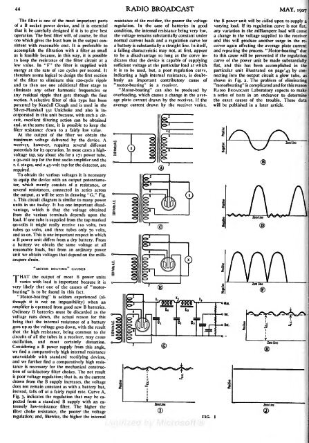
44 RADIO BROADCAST MAY. <strong>1927</strong>The filter is one of the most important partsof a B socket power device, and it is essentialthat it be carefully designed if it is to give bestoperation. The best filter will, of course, be thatone which gives the least hum in the output consistentwith reasonable cost. It is preferable toaccomplish the filtration with a filter as smallas is feasible because, in this way, it is possibleto keep the resistance of the filter circuit at alow value. In " F" the filter issupplied withenergy at the rate of 120 cycles per second. Ittherefore seems logical to design the first sectionof the filter to eliminate this ISO-cycle rippleand to then use one additional filter stage toeliminate any other harmonic frequencies orany residual ripple that gets through the firstsection. A selective filter of this type has beenpatented by Kendall dough and is used in theSilver-Marshall 331 Unichoke and also is incorporatedin this unit because, with such acircuit,excellent filtering action can be obtainedand, at the same time, it is possible to keep thefilter resistance down to a fairly low value.At the output of the filter we obtain thethe device. Amaximum voltage delivered byreceiver, however, requires several differentpotentials for its operation. In most cases a highvoltagetap, say about 180 for a 171 power tube,a go-volt tap for the first audio amplifier and ther. f. stages, and a 45-volt tap for the detector, areresistance of the rectifier, the poorer the voltage the B power unit will be called upon to supply aregulation. In the case of batteries in good varying load. If its regulation curve is not flat,condition, the internal resistance being very low, any variation in the milliampere load will causethe voltage remains substantially constant under a change in the voltage supplied to the receivernormal current loads and a regulation curve for and this will produce another surge in the receiveragain affecting the average plate currenta battery is substantially a straight line. In itself,a falling characteristic may not, at first, appear and repeating the process. "Motor-boating" dueto be a disadvantage so long as the curve indicatesthat the device is capable of supplying curve of the power unit be made substantiallysufficient voltage at the particular load at which flat, and this has been accomplished in theto this cause will be preventedif the regulationit is to be used, but, a poor regulation curve, particular unit illustrated on page 43 by connectinginto the output circuit a glow tube, asindicating a high internal resistance, is doubtlesslyan important contributory cause of shown in Fig. 2. The problem of eliminating"motor-boating" in a receiver."motorboating" is complicated and for this reason"Motor-boating" can also be produced by RADIO BROADCAST Laboratory expects to makeoverloading, which causes a change in the averageplate current drawn by the receiver. If the the exact causes of the trouble. These dataa series of tests in an endeavor to determineaverage current drawn by the receiver varies. will be published in a later article.required.To obtain the various voltages it is necessaryto equip the device with an output potentiometer,which merely consists of a resistance, orseveral resistances, connected in series acrossthe output, as will be seen in drawing "G," Fig.I. This circuit diagram is similar to many powerunits in use to-day. It has one important disadvantage,which is that the voltage obtainedfrom the various terminals depends upon theload. If one tube issupplied from the tap markedgo-volts it might really receive 1 10 volts, twotubes 90 volts, and three tubes only 70 volts,and so on. This is one important respect in whicha B power unit differs from a dry battery. Froma battery we obtain the same voltage at allreasonable loads, but from an ordinary powerunit we obtain voltages that depend on the milliamperedrain."MOTOR BOATING" CAUSESTHAT the output of most B power unitsvaries with load isimportant because it isvery likely that one of the causes of "motorboating"is to be found in this fact."Motor-boating" is seldom experienced (althoughit is not an impossibility) when anamplifier is operated from good new B batteries.Ordinary B batteries must be discarded as thevoltage runs down, the actual reason for thisbeing that the internal resistance of a batterygoes up as the voltage goes down, with the resultthat the high resistance, being common to thecircuits of all the tubes in a receiver, may causeoscillation, and most certainly distortion.Considering a B power supply from this angle,we find a comparatively high internal resistanceunavoidable with standard rectifying devices,and we further find a comparatively high resistanceis necessary for the mechanical constructionof satisfactory filter chokes. The net resultispoor voltage regulation; that is, as the currentdrawn from the B supply increases, the voltagedoes not remain constant as with a battery but,instead, falls off at a fairly rapid rate. Curve A,Fig. 3, indicates the regulation that may be expectedfrom a standard B supply with an extremelylow-resistance filter. The higher thefilter choke resistance, the poorer the voltageregulation; and, likewise, the higher the internalZero LineFIG.IZero Line
MAY, <strong>1927</strong> PERFECTING THE SOCKET POWER DEVICE 45entire unit. No particular care is necessary inthe way in which the wires are run since thereis little danger of feed-back. Just run thewires in the most convenient way to the variousterminals. By reference to the circuit diagram itwill be noted that a switch, marked Sw., isindicated in the primary of the power transformer.This switch is part of the glow tubebase. The terminals in the glow tube correspondingplate and minus A (minus A as indicatedon the Silver-Marshall socket) are shortcircuitedinside of the tube base wiring. Therefore,the lead from the unit that connects to the1O -8 10 volts a. c. is cut and one end connected toto glow tube theColor code on Condenser Bank . Cplate terminal of the glow tube socket (righthandBlue -2 mid Green - 1 midsocket) and the other end connected toHed - 4 mid. Black = commothe negative filament terminal of this samesocket. With this connection, the powerFIG. 2thereby automatically cut off if the glow tube ispulled out of its socket. This is necessary because,The use of a glow tube to improve the regulationof a socket power device is a comparatively used in the model constructed in the Laboratory practically 180 volts at the go-volt tap.The parts mentioned in the above list were with the glow tube removed, there will berecent development. The effectiveness of this and are known to give good results. There is no operation, there are practically no precautionsto be observed; the unit is foolproof. Thetube can be readily seen by referring to the reason why the parts of other manufacturerscurves B, C, and D in Fig. 3, and noticing that might not be substituted provided care is taken four B-battery leads from the receiver arethe voltage at the go-volt tap varies only 5 volts to make certain that the electrical characteristics simply connected to the similarly marked postsBetween a load of o milliamperes to 45 milliamseres.The tube also affects the regulation of the The Amsco type 125 resistance was not used on, and reception obtained by tuning the receiverof the substituted parts are equivalent.on the B unit, the receiver and B unit turnedother voltage taps on the device so that all of in the model made up and illustrated in the in the usual fashion. The 175 volts at 20 milliamperes,obtainable from the i8o-volt tap, willthe taps show a comparatively small variation photograph on page 43. It will be found thatvoltage with change in load. The voltage regulationat the go-volt tap is most important since resistance shown in the photograph.go-volt tap will supply up to 45 mils, at thisthis tap generally supplies a majority of the Satisfactory block condensers are also made by voltage; the 45-volt tap up to 10 mils., as shownthe type 125 unit is one inch longer than the operate a ux-171 type tube to perfection. Thetubes in a receiver. The use of a glow tube with Silver-Marshall, Tobe Deutschmann, Aerovox, by Fig. 3. There is no danger of damaging tubesthe concomitant improvement in the regulation Sangamo, Muter, Faradon, and the resistors that and condensers in the receiver due to highvoltagesurges from the B unit, since the voltagecurve will eliminate a factor (poor regulation) are used may be the products of any reputablewhich certainly has a very definite tendency to manufacturer provided they are capable of of the high tap can never rise above 190 volts.cause "motor-boating," and it is suggested that, carrying the currents that are specified. The In use, the two lighted filaments of the cxti3rectifier tube will cause the tube to getwith any B power unit that iswhere possible, the tube be used in conjunction S-M 653 resistor (Ward Leonard S 1 1500), costing82.50, can be used in place of the Amsco rather warm; at no time should the plates evercausing a gr^-atdeal of trouble.resistors and mounts.become red due to heating. The glow tube willAs was mentioned at a previous point in this The construction of the unit isvery simple. glow with a bluish or pinkish light, and thisarticle, an important feature of the socket power Upon the 7" by 10" wood base, beginning at the may possibly flicker when a very strong signal isunit illustrated herein is that it may be connectedto any standard receiver drawing normal down with the Dubilier condenser bank along of the tube. If too great current more than 45left-hand rear, the power transformer is screwed being received, due to the reciprocating actioncurrent with the certainty that the voltages will side of it, and the Unichoke at the right-hand milliamperes is drawn from the go-volt tap ofFall within the practically required operating end. The socket for the type 313 tube isplaced the unit, the glow tube may cease to glow. Turningimmediately result in thislimits, by virtue of the fact that a glow tube is directly in front of the transformer, while thatemployed. In an ordinary B unit, variable high for the 374 glow tube is placed directly in front tube re-lighting, after which the set mayresistances are used to control the output voltage,and it is seldom that the user has any de-are lined up in front of the sockets, and then, in is drawn by the go-volt receiver circuit, it shouldof the Unichoke. The three resistance mounts again be turned on. If more than 45 milliamperesfinite idea what voltages are being applied to his front of the resistance mounts, are placed four be examined for trouble. The brilliancy of thereceiver.Fahnestock clips. The left-hand clip is negative, glow in the cx-374 regulator tube will vary withThe parts necessary to build a B socket power and progressing to the right, we have the plus different loads.employing the principles outlined in this article, 45-, plus 90-, andare listed below:3coplus i;8o-volttaps. WiringLIST OF PARTSmost of the unitsR Cunningham cx-3 13 Rectifier Tube $ 5.00 can be done withoutsoldering, ifG Cunningham cx-374 Glow Tube 5.50T S-M 329 Power Transformer, withdesired, by simply5-volt balanced filament winding,two 2oo-volt secondaries,fastening thescraped ends ofand electrostatic shield . . . o.oo the connectingL S-M 331 Unichoke .... H.oo wire under theC Dubilier Type PL 381 Condens-jrterminal screws ofBank 14.00 those units whichTwo S-M 5 1 1 Tube Sockets . . i .00 are so equipped.Ri Amsco ijoo-Ohm Resistor withThe circuit diagramgiven in Fig.Mounts . .5oMA. Type 125 2.R-2 Amsco 4ooo-Ohm Resistor loMA.2 is marked withCapacity.QO terminal numbersR Amsco 6ooo-Ohm Resistor loMA.which correspondCapacity .90 to those on theTwo Amsco Resistor Mounts ..30 parts that wereFour Fahnestock Clips. . . .087" x 10" Wood used in this Base with 17 No.particularmodel,6, \", R. H., wood screws, and 15and this will aidfeet of Kellogg fabric insulatedin making it a20 25 30LOAD CURRENT IN MILLIAMPEREShook-up wire .50 simple matter toTOTAL 47.18 correctly wire the FIG. 3
- Page 1 and 2: RADIO BROADCASTVOLUME XIMAY, 1927,
- Page 3 and 4: INDEX.ContinuedPAGEThreshold of Hea
- Page 5 and 6: RADIO BROADCAST ADVERTISERALUMINUMB
- Page 7 and 8: RADIO BROADCAST ADVERTISERfIA REALA
- Page 9 and 10: :RADIO BROADCASTVOLUME XI NUMBER 1M
- Page 11 and 12: MAY, 1927WITH MACMILLAN TO THE ARCT
- Page 13: THE MARCHInterpretation of Current
- Page 16 and 17: 18volved the law in precarious lega
- Page 18 and 19: The ElectricalA Non-Technical Expla
- Page 20 and 21: 22 RADIO BROADCAST MAY, 1927type of
- Page 22 and 23: A Balanced Short-Wave ReceiverA Des
- Page 24 and 25: What About the A BatteryThe Importa
- Page 26 and 27: 28 RADIO BROADCAST MAY, 1927The cas
- Page 28 and 29: 30 RADIO BROADCAST MAY, 1927NO STRA
- Page 30 and 31: 32 RADIO BROADCAST MAY, 1927from th
- Page 32 and 33: 34 RADIO BROADCAST MAY, 1927the ave
- Page 34 and 35: AS THE BROADCASTER SEES ITDrawings
- Page 36 and 37: 38 RADIO BROADCAST MAY, 1927Interes
- Page 38 and 39: Some Facts About Coil DesignThe Osc
- Page 40 and 41: 42 RADIO BROADCAST MAY, 1927Shows e
- Page 44 and 45: ''Measuring TubeCharacteristicsA Pa
- Page 46 and 47: 48 RADIO BROADCAST MAY, 1927MUTUAL
- Page 48 and 49: 50 RADIO BROADCAST MAY, 1927whose b
- Page 50 and 51: RADIO BROADCAST ADVERTISERThe Radio
- Page 52 and 53: 54 RADIO BROADCAST ADVERTISERA Bett
- Page 54 and 55: 56 RADIO BROADCAST ADVERTISERNo. 94
- Page 56 and 57: .58 RADIO BROADCAST ADVERTISERTJour
- Page 58 and 59: 60 RADIO BROADCAST ADVERTISERMire's
- Page 60 and 61: ''. ..RADIO BROADCAST ADVERTISERin