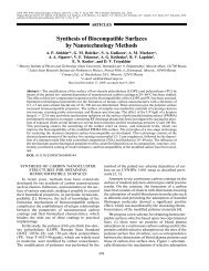
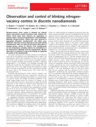
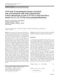
This article has been accepted <strong>for</strong> publication in a future issue of this journal, but has not been fully edited. Content may change prior to final publication.2Figure 1.z-axiscontrollerx, y-axiscontrollerSample-1-1Piezoelectric tubescannerPhotodetectorLaserBasic AFM schematic with feedback controllers.Micro-cantileverTipx, y positionsensorsmodeled to determine the feed<strong>for</strong>ward input to account <strong>for</strong> thevibration effects. Their results indicated that the inclusion offeed<strong>for</strong>ward input reduces the tracking error more as comparedto using only feedback control. Other examples of successfulapplications of feedback control techniques include [13]–[17]. An exhaustive review of the literature can be found inreference [9].The use of feedback controllers in damping and linearizingthe piezoelectric tube scanner has been shown to be successfulin the above mentioned works [10]–[17]. However,these feedback controllers have little success in tracking highfrequency triangular wave<strong>for</strong>ms. Closed-loop tracking of thesewave<strong>for</strong>ms typically results in the corners of the triangularwave<strong>for</strong>m to be rounded off. This is due to the presenceof high frequency harmonics that are inevitably outside ofthe bandwidth of the closed-loop system. Consequently, AFMimages generated at high speeds often demonstrate significantdistortions especially around the edges of the image.This paper proposes a new scan technique <strong>for</strong> fast atomic<strong>for</strong>ce microscopy by <strong>for</strong>cing the scanner to follow a spiraltrajectory over the surface that is to be imaged. A constant angularvelocity (CAV) spiral scan can be produced by applyingslowly varying-amplitude single frequency sinusoidal signalsto the x- and y-axes of the piezoelectric tube scanner. The useof the single frequency input signals allows <strong>for</strong> scanning to beper<strong>for</strong>med at very high speeds without exciting the resonanceof the scanner and with relatively small control ef<strong>for</strong>ts. Analternative method is to generate the spiral pattern in a constantlinear velocity (CLV) approach. The latter method has beenimplemented in some disk storage devices, such as CompactDisk-Read Only Memory (CD-ROM) where the in<strong>for</strong>mationis stored in a continuous spiral track over the disk’s surface[18]. The proposed method is an alternative to raster-basedsinusoidal scan methods that are used to achieve fast scans ine.g., scanning near-field optical microscopy (SNOM) [19]. Inspiral scanning, both axes follow sinusoidal signals of identicalfrequencies resulting in a smooth trajectory. This avoids thetransient behavior that may occur in sinusoidal scans as theprobe moves from one line to the next. Furthermore, theproposed method does not require specialized hardware, e.g.a tuning <strong>for</strong>k actuator, and can be implemented on a standardAFM with minor software modifications.It should be noted that recently a few prototype laboratoryAFMs have been developed that are capable of imaging asample at, or close to, video-rates, [20]–[23]. Such a functionalityis particularly useful in a number of applications, e.g.when capturing the dynamic behavior of certain biomolecularprocesses is needed. In order to achieve video rates, using araster scanned AFM, the scan frequency has to be quite high,close to 5 kHz or higher. The spiral scanning method proposedin this paper may be a good candidate <strong>for</strong> such applications.This scheme can be easily implemented on a commercial,or prototype AFM, with minimal software modifications. Itshould be pointed out that to operate an AFM at such high scanfrequencies one has to overcome other technical challenges,such as the need to utilize very small micro-cantilevers withextremely high resonance frequencies [20].The remainder of this paper is organized as follows. Thegeneration of input signals to produce the spiral pattern is describedin detail in Section II. Section III provides descriptionsof the AFM and other experimental setups used in this work.Modeling and identification of the system transfer functionsare presented in Section IV. Control schemes <strong>for</strong> the AFMscanner are devised in Section V. In Section VI experimentalresults are presented to illustrate the drastic improvement inimaging speed that can be achieved with the proposed newscan trajectory. Finally, Section VII concludes the paper.II. SPIRAL SCA<strong>NT</strong>his section deals with the generation of input signals thatare needed to move the AFM scanner in a spiral pattern,illustrated in Fig. 2. The pattern is known as the Archimedeanspiral. A property of this spiral is that its pitch P, which isdistance between two consecutive intersections of the spiralcurve with any line passing through the origin, is constant[24]. Depending on how this trajectory is traced, the shape isreferred to as either a Constant Angular Velocity (CAV) spiral,or a Constant Linear Velocity (CLV) spiral. In the <strong>for</strong>mer case,the pattern is traced at a constant angular velocity, while inthe latter at a constant linear velocity.A. The CAV spiralThe equation that generates a CAV spiral of pitch P atan angular velocity of ω can be derived from a differentialequation given in [18] asdrdt = Pω(1)2πwhere r is the instantaneous radius at time t. Equation (1) issolved <strong>for</strong> r by integrating both sides to obtain∫dr = Pω ∫dt. (2)2πFor r = 0 at t = 0,r = P ωt. (3)2πHere, P is calculated asspiral radius × 2P = (4)number o f curves − 1Copyright (c) 2009 IEEE. Personal use is permitted. For any other purposes, Permission must be obtained from the IEEE by emailing pubs-permissions@ieee.org.Authorized licensed use limited to: University of <strong>New</strong>castle. Downloaded on November 26, 2009 at 00:02 from IEEE Xplore. Restrictions apply.
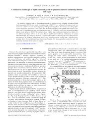
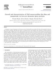
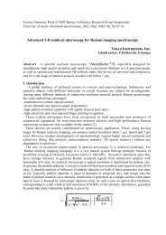
This article has been accepted <strong>for</strong> publication in a future issue of this journal, but has not been fully edited. Content may change prior to final publication.363Pxs (µm)6303(a)ys (µm)0361 2 3 4 5 6 76 3 0 3 6x s (µm)Figure 2. Spiral scan of 6 µm radius with number o f curve = 8.where number o f curves is defined as the number of timesthe spiral curve crosses through the line y = 0. This isexemplified in Fig. 2 where the crossing points are numbered.The figure illustrates a spiral scan of 6 µm radius withnumber o f curves = 8.The equation that describes the total scanning time t total associatedwith a CAV spiral scan can be derived by integratingboth sides of equation (1) as∫r end∫t enddr = Pω dt (5)2πr start t startwhere r start and r end are initial and final values of the spiralradius, and t start and t end are initial and final values of thescanning time. From equation (5), if r start = 0 at t start = 0 andt total = t end −t start , we obtaint total = 2πr endPω . (6)In order to implement the spiral scans using a piezoelectrictube scanner, equation (3) needs to be translated into cartesiancoordinates. The trans<strong>for</strong>med equations areandx s = r cosθ (7)y s = r sinθ (8)where x s and y s are input signals to be applied to the scanner inthe x and y axes respectively and θ is the angle. From ω =dt dθ ,θ is obtained as θ = ωt. An example of input signals x s andy s that can generate the spiral in Fig. 2 is plotted in Fig. 3.The figure illustrates constant phase errors between the inputsignals and measured outputs. Such errors are due to the nonidealfrequency response of the controlled nanopositioner. Fora CAV spiral, these phase errors can be easily eliminated byadding phase constants α x and α y to shape the input signalsasX s = r cos(θ + α x ) (9)andY s = r sin(θ + α y ). (10)8ys (µm)60 0.04 0.08 0.12t (s)(b)630360 0.04 0.08 0.12t (s)Figure 3. Input signals to be applied to the scanner in the x and y axes ofthe scanner to generate CAV spiral scan with ω = 188.50 radians/sec. Solidline is the achieved response and dashed line is the desired trajectory.Here, α x and α y are determined by measuring the closed-loopfrequency response of the system at the scan frequency. Theymay also be determined off-line if a model of the system isat hand.A key advantage of using a CAV spiral is that closed-looptracking of this pattern when implemented via the cartesianequations only involves tracking single frequency sinusoidalsignals with slowly varying amplitudes. This advantage, whencombined with the use of the shaped input signals (9) and (10),enables the AFM’s scanner to track a high frequency CAVspiral resulting in fast atomic <strong>for</strong>ce microscopy. A drawbackof this method is that its linear velocity v is not constant. Thus,it may not be suitable <strong>for</strong> scanning some samples where theinteraction between the probe and the sample needs to be doneat linear velocity. The CLV spiral presented next overcomesthis problem.B. The CLV spiralIn order to generate a CLV spiral, the radius ˜r and angularvelocity ˜ω need to be varied simultaneously in a way thatthe linear velocity of the nanopositioner is kept constant atall times. The expressions <strong>for</strong> ˜r and ˜ω are first derived bysubstituting ω = v rinto equation (1) to obtaindrdt = Pv(11)2πrwhere v is the linear velocity of the CLV spiral. Then, equation(11) is solved <strong>for</strong> r by integrating both sides of the equationas∫rdr = Pv ∫dt. (12)2πFor r = 0 at t = 0, we obtain√Pv˜r = t. (13)πFrom equation (13), by substituting ˜r = ṽ the expression <strong>for</strong>ω˜ω is obtained as √πv˜ω =Pt . (14)Copyright (c) 2009 IEEE. Personal use is permitted. For any other purposes, Permission must be obtained from the IEEE by emailing pubs-permissions@ieee.org.Authorized licensed use limited to: University of <strong>New</strong>castle. Downloaded on November 26, 2009 at 00:02 from IEEE Xplore. Restrictions apply.