A New Scanning Method for Fast Atomic Force Microscopy - NT-MDT
A New Scanning Method for Fast Atomic Force Microscopy - NT-MDT
A New Scanning Method for Fast Atomic Force Microscopy - NT-MDT

You also want an ePaper? Increase the reach of your titles
YUMPU automatically turns print PDFs into web optimized ePapers that Google loves.
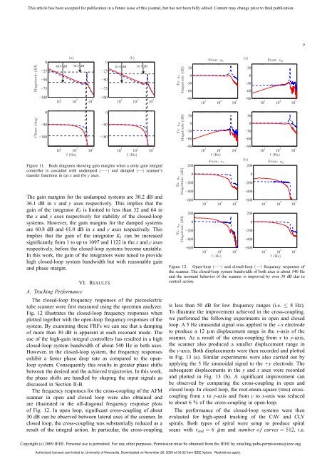
This article has been accepted <strong>for</strong> publication in a future issue of this journal, but has not been fully edited. Content may change prior to final publication.9Magnitude (dB)Phase (deg)0255075100090180(a)(b)060.8 dB 30.2 dB 61.0 dB 36.1 dB2510 1 10 2 10 310 1 10 2 10 3f (Hz)507510009018010 1 10 2 10 310 1 10 2 10 3f (Hz)Figure 11. Bode diagrams showing gain margins when a unity gain integralcontroller is cascaded with undamped (−−) and damped (—) scanner’stransfer functions in (a) x and (b) y axes.The gain margins <strong>for</strong> the undamped systems are 30.2 dB and36.1 dB in x and y axes respectively. This implies that thegain of the integrator K I is limited to less than 32 and 64 inthe x and y axes respectively <strong>for</strong> stability of the closed-loopsystems. However, the gain margins <strong>for</strong> the damped systemsare 60.8 dB and 61.0 dB in x and y axes respectively. Thisimplies that the gain of the integrator K I can be increasedsignificantly from 1 to up to 1097 and 1122 in the x and y axesrespectively, be<strong>for</strong>e the closed-loop systems become unstable.In this work, the gain of the integrators were tuned to providehigh closed-loop system bandwidth but with reasonable gainand phase margin.A. Tracking Per<strong>for</strong>manceVI. RESULTSThe closed-loop frequency responses of the piezoelectrictube scanner were first measured using the spectrum analyzer.Fig. 12 illustrates the closed-loop frequency responses whenplotted together with the open-loop frequency responses of thesystem. By examining these FRFs we can see that a dampingof more than 30 dB is apparent at each resonant mode. Theuse of the high-gain integral controllers has resulted in a highclosed-loop system bandwidth of about 540 Hz in both axes.However, in the closed-loop system, the frequency responsesexhibit a faster phase drop rate as compared to the openloopsystem. Consequently this results in greater phase shiftsbetween the desired and the achieved trajectories. In this work,the phase shifts are handled by shaping the input signals asdiscussed in Section II-B.The frequency responses <strong>for</strong> the cross-coupling of the AFMscanner in open and closed loop were also obtained andare illustrated in the off-diagonal frequency response plotsof Fig. 12. In open loop, significant cross-coupling of about30 dB can be observed between lateral axes of the scanner. Inclosed loop, the cross-coupling was substantially reduced as aresult of the integral action. In particular, the cross-couplingTo: uyTo: uxMagnitude (dB) Magnitude (dB)To: uyTo: uxMagnitude (dB) Magnitude (dB)30030609030030609020002004006002000200400600From: u x10 1 10 2 10 310 1 10 2 10 3f (Hz)From: u x10 1 10 2 10 310 1 10 2 10 3f (Hz)(a)300306090300306090(b)20002004006002000200400600From: u y10 1 10 2 10 310 1 10 2 10 3f (Hz)From: u y10 1 10 2 10 310 1 10 2 10 3f (Hz)Figure 12. Open-loop (−−) and closed-loop (—) frequency responses ofthe scanner. The closed-loop system bandwidth of both axes is about 540 Hzand the resonant behavior of the scanner is improved by over 30 dB due tocontrol action.is less than 50 dB <strong>for</strong> low frequency ranges (i.e. ≤ 8 Hz).To illustrate the improvement achieved in the cross-coupling,we per<strong>for</strong>med the following experiments in open and closedloop. A 5 Hz sinusoidal signal was applied to the +x electrodeto produce a 12 µm displacement range in the x-axis of thescanner. As a result of the cross-coupling from x to y-axis,the scanner also produced a smaller displacement range inthe y-axis. Both displacements were then recorded and plottedin Fig. 13 (a). Similar experiments were also carried out byapplying the 5 Hz sinusoidal signal to the +y electrode. Thesubsequent displacements in the y and x axes were recordedand plotted in Fig. 13 (b). A significant improvement canbe observed by comparing the cross-coupling in open andclosed loop. In closed loop, the root-mean-square (rms) crosscouplingfrom x to y-axis and from y to x-axis was reducedto about 6 % of the cross-coupling in open-loop.The per<strong>for</strong>mance of the closed-loop systems were thenevaluated <strong>for</strong> high-speed tracking of the CAV and CLVspirals. Both types of spiral were setup to produce spiralscans with r end = 6 µm and number o f curves = 512, i.e.Copyright (c) 2009 IEEE. Personal use is permitted. For any other purposes, Permission must be obtained from the IEEE by emailing pubs-permissions@ieee.org.Authorized licensed use limited to: University of <strong>New</strong>castle. Downloaded on November 26, 2009 at 00:02 from IEEE Xplore. Restrictions apply.