2002 Replacement Parts Catalog - cedip
2002 Replacement Parts Catalog - cedip
2002 Replacement Parts Catalog - cedip
- No tags were found...

Create successful ePaper yourself
Turn your PDF publications into a flip-book with our unique Google optimized e-Paper software.
Cameron Elastomer Technology employees are experts in elastomer technology andcan take an idea from the testing phase through full product development.Today, there is a family of elastomer products specially formulated and designed tomeet the rigorous demands of the oilfield. These products, when used in CameronU, UII, T, TL, UL and UM, and C ram and D and DL annular BOPs, improve performance,extend service life, reduce downtime, and lower operating costs.CAMRAM, CAMRAM 350, CAMULAR , VBR-II, FLEXPACKER-NR andCAMLAST elastomer and DUROCAM elastomer have set new standards in performance.Each is uniquely Cameron, including design and manufacturing. Behindeach product is the absolute commitment to quality, performance and support thatthe industry has come to recognize as hallmarks of Cameron. CET is ISO 9001 and APIQ certified.An integral part of CET’s Katy facility is a temperature controlled elastomer warehouse.CET manufactured elastomer products and critical drilling metal spares arereadily available to meet customer requirements.BOP Elastomer <strong>Replacement</strong> <strong>Parts</strong>650 Ton Integrated Computer ControlledInjection Molding CenterTC1001 8 © <strong>2002</strong> Cooper Cameron, Cameron Division
Comparison of Cameron Ram-Type Blowout PreventersCameron offers a wide range of ram-type BOPs to meet the dynamic needs of thedrilling industry. The Cameron U BOP was initially designed for underwater drillingand is now the most widely used land BOP. Today, there are more U BOPs in thefield worldwide than any other ram-type BOP in the industry. As technology and theneeds of the drilling industry changed, Cameron responded by developing newram-type BOP designs. Cameron introduced the U II BOP for subsea applications andhas since developed the T BOP and the TL, UL and UM models for land and subseaapplications. Regardless of the model, all of the pressure containing components inCameron ram-type BOPs are forged to provide added safety and reliability.Comparison of Cameron Ram-Type BOPsDescription TL BOP UM BOP U BOPBore Sizes Working Pressures Working Pressures Working Pressures7-1/16” - 3000 psi WP 3000 psi WP- 5000 psi WP 5000 psi WP- 10,000 psi WP 10,000 psi WP- 15,000 psi WP 15,000 psi WP11” - - 3000 psi WP- 5000 psi WP 5000 psi WP- 10,000 psi WP 10,000 psi WP- 15,000 psi WP 15,000 psi WP13-5/8” - - 3000 psi WP- - 5000 psi WP10,000 psi WP 10,000 psi WP 10,000 psi WP- 15,000 psi WP 15,000 psi WP16-3/4” - - 3000 psi WP- - 5000 psi WP- - 10,000 psi WP18-3/4” 5000 psi WP - -10,000 psi WP - 10,000 psi WP15,000 psi WP - -20-3/4” - - 3000 psi WP21-1/4” - - 2000 psi WP- - 5000 psi WP- - 10,000 psi WP26-3/4” - - 3000 psi WPSide Ram Removal Yes No NoHydraulic StudTensioning*Not Required No Available on large sizesBonnet Seal Carrier Standard Available AvailableMechanical orHydromechanical LockingMechanismRamLocks/ST-Lock/WedgelocksWedgelocksWedgelocks*Not required when using bonnet seal carrierTC1001 9 © <strong>2002</strong> Cooper Cameron, Cameron Division
U BOP Hydraulic Control SystemThe U blowout preventer is designed so that hydraulic pressure opens and closes the rams and provides themeans for quick ram change-out.Ram closing pressure closes the rams. When the bonnet bolts are removed, closing pressure opens the bonnet.After the bonnet has moved to the fully extended position, the ram is clear of the body. An eyebolt can be installedin the top of each ram to lift it out of the preventer.Ram opening pressure opens the rams. Following ram change-out, this pressure closes the bonnets. The rams arepulled outward, near the bonnets, before the bonnets begin moving toward the preventer body. This assuresthat the rams never obstruct the bore or interfere with the pipe in the hole. Hydraulic pressure draws the bonnetstightly against the preventer body and the bonnet bolts are reinstalled to hold the bonnets closed.U BOP Operating Data and Fluid RequirementsLarge Bore Shear Bonnet Operating Data and Fluid RequirementsBore Size andWorkingPressureGals toOpenPipe Rams(1 Set)Gals toClosePipeRams(1 Set)LockingScrewTurns(Each End)ClosingRatioOpeningRatioBore Size andWorkingPressureGals to OpenPipe Rams(1 Set)Gals toClosePipe Rams(1 Set)LockingScrew Turns(Each End)7-1/16” All WP 1.3 1.3 18 6.9:1 2.2:1 7-1/16” All WP - - - - -11” Except 15,000 psi 3.4 3.5 27 7.3:1 2.5:111” Except 15,000psiClosingRatioOpeningRatio6.8 6.0 27 12.0:1 4.8:111” 15,000 psi 5.7 5.8 32 9.8:1 2.2:1 11” 15,000 psi 8.9 9.0 32 15.2:1 3.7:113-5/8” Except15,000 psi13-5/8” 15,000 psiModel B16-3/4” 3000 psiModel B16-3/4” 5000 psiModel B5.5 5.8 32 7.0:1 2.3:110.4 10.6 45 10.6:1 3.6:19.8 10.6 38 6.8:1 2.3:19.8 10.6 38 6.8:1 2.3:113-5/8” Except15,000 psi13-5/8” 15,000 psiModel B16-3/4” 3000 psiModel B16-3/4” 5000 psiModel B10.5 10.9 32 10.8:1 4.5:116.0 16.2 45 16.2:1 6.0:118.2 19.0 38 10.4:1 4.4:118.2 19.0 38 10.4:1 4.4:116-3/4” 10,000 psi 11.6 12.5 45 6.8:1 2.3:1 16-3/4” 10,000 psi 18.2 19.1 45 10.4:1 4.4:118-3/4” 10,000 psi 21.3 23.1 54 7.4:1 3.7:1 18-3/4” 10,000 psi - - - - -20-3/4” 3000 psi 8.1 8.7 46 7.0:1 1.3:1 20-3/4” 3000 ps 14.3 14.9 46 10.8:1 1.7:121-1/4” 2000 psi 9.0 8.7 46 7.0:1 1.3:1 21-1/4” 2000 psi 14.3 14.9 46 10.8:1 1.7:121-1/4” 5000 psi 27.3 30.0 54 7.2:1 4.0:1 21-1/4” 5000 psi - - - - -21-1/4” 10,000 psi 24.5 26.9 51 7.2:1 4.0:1 21-1/4” 10,000 psi - - - - -26-3/4” 3000 psi 10.1 10.8 58 7.0:1 1.0:1 26-3/4” 3000 ps - - - - -TC1001 12 © <strong>2002</strong> Cooper Cameron, Cameron Division
U BOP SpecificationsThe following specifications apply to typical Cameron U type BOPs. Your Cameron representativecan provide information on non-standard BOP assemblies.• Side outlets to 4-1/16” (7-1/16” on 26-3/4” BOPs) can be provided beneatheach set of rams on either or both sides of U BOPs. Side outlets can bestudded, open-face flange or clamp hub with the same pressure rating as thevertical run connections.• Flanges conform to API standard 6A and/or 16A. Hubs conform to API 16A orapplicable standards. Type 6BX flanges are standard for 10,000 and 15,000 psiworking pressures and for 5000 psi for 13-5/8” and larger bore BOPs.Hydraulic control connections for operation of rams and bonnets are 1” NPT. There aretwo connections for each set of rams. Wedgelock connections are ½” NPT.The capital letters in the following designations refer to the U BOP dimensional viewsand dimensional charts shown on the following pages.A-1 Length - bonnets closed, locking screws lockedA-2 Length - bonnets opened, locking screws unlockedA-3 Length - bonnets closed, with wedgelocksA-4 Length - bonnets opened, with wedgelocksB-1 Height - flangedB-2 Height - clamp hubsB*** Height - added height if 30” spacing is required for doubleCDWidth - no side outletsCenterline of preventer to outlet flange or hub face. This distance is variable andmust be determined per individual specifications.E-1 Centerline of side outlet below rams to bottom flange faceE-2 Centerline of side outlet below rams to bottom hub faceF-1 Top of upper ram to top flange faceF-2 Top of upper ram to top hub faceG Height of ramH-1 Centerline of side outlet between rams to bottom flange faceH-2 Centerline of side outlet between rams to bottom hub faceJ Top of lower ram to bottom of upper ramTC1001 13 © <strong>2002</strong> Cooper Cameron, Cameron Division
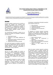
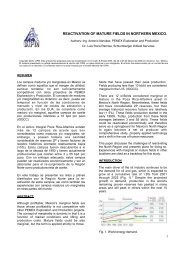
7-1/16” 3000 - 11” 10,000 psi WP U BOP Part NumbersItemNo.DescriptionQtySglQtyDbl7-1/16”3000psiModel II7-1/16”5000psiModel II1 Body 1 1 - - - - - - -2 Intermediate Flange 2 4 030266-03-00-01 030266-03-00-01 030266-01-01 030266-01-01 030267-03 030267-03 030267-032A Intermediate Flange/Shear - - 041499-03** 041499-03** 041499-01** 041499-01** 041457-03** 041457-03** 041457-03**3 Bonnet 2 4 030278-04 030278-04 030278-02 030278-01 030268-01 030268-02 030268-034 Ram Assembly 2 4 644504-( ) 644504-( ) 644504-( ) 644504-( ) 644219-( ) 644219-( ) 644219-( )5 Piston, Operating 2 4 2010520-03 2010520-03 2010520-03 2010520-03 673178 673178 163129-015A Piston, Operating/Shear - - 049116-01** 049116-01** 049116-01** 049116-01** 698914** 698914** 698914**6 Cylinder, Operating 2 4 030274-02 030274-02 030274-02 030274-02 030274-03 030274-03 030274-036A Cylinder, Operating/Shear - - 041365-02 041365-02 041365-02 041365-02 041365-03** 041365-03** 041365-03**7 Housing, Locking Screw 2 4 030308-01 030308-01 030308-01 030308-01 030308-02 030308-02 030308-028 Locking Screw 2 4 030326 030326 030326 030326 030365 030365 0303658A Locking Screw/Shear - - 049258-01 049258-01 049258-01 049258-01 046628-01 046628-01 046628-019 Piston, Ram Change/Open 2 4 030324 030324 030324 030324 030362 030362 03036210 Piston, Ram Change/Close 2 4 030325 030325 030325 030325 030363 030363 03036311 Cylinder, Ram Change 4 8 030273-02 030273-02 030273-02 030273-02 030273-03 030273-03 030273-0312 Bolt, Bonnet 8 16 030312-06 030312-06 030312-07 030312-01 030312-04 030312-03 030312-0512A Bolt, Bonnet/Shear - - 041366-06 041366-06 041366-07 041366-22 041366-04 041366-03 041366-0513 Stud, Locking Screw Housing 16 32 219065-10-04-41 219065-10-04-41 219065-10-04-41 219065-10-04-41 219065-12-05-01 219065-12-05-01 219065-12-05-0113A Stud, Locking Screw Housing/Shear - - 038732-57-00-54 038732-57-00-54 219065-10-05-41 219065-10-05-41 219065-12-06-51 219065-12-06-51 219065-12-06-5114 Nut, Locking Screw Housing 16 32 2709000-10-01 2709000-10-01 2709000-10-01 2709000-10-01 2709000-12-01 2709000-12-01 2709000-12-0115 Check Valve, Plastic Packing 2 4 M517988 M517988 M517988 M517988 M517988 M517988 M51798816 Screw, Plastic Packing 2 4 005940-09 005940-09 005940-09 005940-09 005940-09 005940-09 005940-0917 Pipe Plug, Plastic Packing 2 4 005930-05-10 005930-05-10 005930-05-10 005930-05-10 005930-05-10 005930-05-10 005930-05-1018 Ring, Plastic Packing 2 4 2010178-01 2010178-01 2010178-01 2010178-01 2010178-02 2010178-02 2010178-0219 Ring, Plastic Energizing 2 4 018586-12 018586-12 018586-12 018586-12 018586-13 018586-13 018586-1320 Seal Ring, Connecting Rod 2 4 212741-37-00-01 212741-37-00-01 212741-37-00-01 212741-37-00-01 212741-38-00-01 212741-38-00-01 212741-38-00-0121 Ring Back-Up 4 8 - - 021792-21 021792-21 021792-22 021792-22 021792-2222 Seal, Bonnet 2 4 644197-01-00-01 644197-01-00-01 644197-01-00-01 644197-01-00-01 644197-02-00-01 644197-02-00-01 644197-02-00-0123 Pin, Ram Guide 4 8 030313-02 030313-02 030313-02 030313-02 030313-03 030313-03 030313-0324 O-Ring, Operating Cylinder 4 8 702645-44-61 702645-44-61 702645-44-61 702645-44-61 702645-45-11 702645-45-11 702645-45-1125 O-Ring, Operating Piston Rod to Int Flg 2 4 018492-92 018492-92 018492-92 018492-92 018492-91 018492-91 018492-9126 Lip Seal, Operating Piston 2 4 710541 710541 710541 710541 710539 710539 71053927 Seal Ring, Tail Rod 2 4 212741-32 212741-32 212741-32 212741-32 212741-33-00-01 212741-33-00-01 212741-33-00-0128 O-Ring, Wiping 2 4 702645-33-11 702645-33-11 702645-33-11 702645-33-11 702645-33-51 702645-33-51 702645-33-5129 O-Ring, Ram Change Piston to Body 4 8 702645-32-41 702645-32-41 702645-32-41 702645-32-41 702645-32-61 702645-32-61 702645-32-6130 O-Ring, Ram Change Piston Rod to Int Flg 4 8 702645-32-91 702645-32-91 702645-32-91 702645-32-91 702645-33-11 702645-33-11 702645-33-1131 O-Ring, Ram Change Cylinder to Int Flg 4 8 702645-33-81 702645-33-81 702645-33-81 702645-33-81 031423-25-13-85 031423-25-13-85 031423-25-13-8532 O-Ring, Ram Change Cylinder to Bonnet 4 8 702645-34-21 702645-34-21 702645-34-21 702645-34-21 2010180-02 2010180-02 2010180-0233 O-Ring, Ram Change Piston 4 8 702645-33-21 702645-33-21 702645-33-21 702645-33-21 702645-33-51 702645-33-51 702645-33-5134 O-Ring, Bonnet Bolt Retainer 8 16 702645-22-31 702645-22-31 702645-22-91 702645-23-21 702645-22-71 702645-22-91 702640-23-4135 Cap Screw, Int Flange to Bonnet 16*** 32*** 702585-22-00-50 702585-22-00-50 702585-22-00-50 702585-22-00-50 702585-25-00-50 702585-25-00-50 702585-25-00-5036 Gland, Bleeder 2 4 017454-08 017454-08 017454-08 017454-08 017454-08 017454-08 017454-0837 Plug, Bleeder 2 4 017454-09 017454-09 017454-09 017454-09 017454-09 017454-09 017454-0938 Lifting Eye 2 2 011849-01 011849-01 011849-01 011849-01 011849-01 011849-01 011849-0139 Packing, Plastic 10 20 007650-25 007650-25 007650-25 007650-25 007650-25 007650-25 007650-2540 Washer 2 4 689523-04 689523-04 689523-04 689523-04 689523-05 689523-05 689523-0541 Ring, Retainer 2 4 018572-83 018572-83 018572-83 018572-83 018572-84 018572-84 018572-8442 Wear Ring, Operating Piston 2 4 049223-03 049223-03 049223-03 049223-03 049223-02 049223-02 049223-0243 Spacer, Shear**** - - 687117-01 687117-01 687117-01 687117-01 687117-02 687117-02 687117-027-1/16”10,000psiModel II7-1/16”15,000psiModel II****A large bore shear bonnet is available for these sizes. For part numbers, see page 24.****Part numbers shown are for old style shear bonnets. For current model large bore shear bonnet part numbers, see page .****13-5/8” through 16-3/4” and 20-3/4” through 26-3/4” require 24 for single and 48 for double. The 18-3/4” requires 32 for single and 64 double.****Required on all 11” 15,000 psi and 16-3/4” 10,000 psi BOPs with manual locking screws.*11”3000psiModel II* 11”5000psiModel II*11”10,000psiModel IITC1001 17 © <strong>2002</strong> Cooper Cameron, Cameron Division
123437363810422911624215161735339526243231301478133141819214041422252320Double U BOPSD017500TC1001 18 © <strong>2002</strong> Cooper Cameron, Cameron Division
11” 15,000 - 16-3/4” 5000 psi WP U BOP Part NumbersItemNo.DescriptionQtySglQtyDbl*11”15,000psiModel 79*13-5/8”3000psiModel II1 Body 1 1 - - - - - - -2 Intermediate Flange 2 4 049391-01 030270-01-00-02 030270-01-00-02 031216 698899 038944 0388442A Intermediate Flange/Shear - - * 686242** 686242** 686767** 615538-01 - 0414083 Bonnet 2 4 031241 030284-02 030284-01 031241 691849 038843-02 038843-014 Ram Assembly 2 4 644222-( ) 644225-( ) 644225-( ) 644225-( ) 644228-( ) 644231-( ) 644231-( )5 Piston, Operating 2 4 698481 679816 679816 678512 698996 614374-01 6895625A Piston, Operating/Shear - - * 687542** 687542** 670512-00-00-02 615539-01 - 694085**6 Cylinder, Operating 2 4 030274-01 030274-01 030274-01 030274-01 030274-06 030274-06 030274-066A Cylinder, Operating/Shear - - - 041365-01** 041365-01** 041365-01** - - 041365-06**7 Housing, Locking Screw 2 4 030308-03 030308-03 030308-03 030308-03 030308-06 030308-06 030308-068 Locking Screw 2 4 030846 030307 030307 030307 695234 038901 0389018A Locking Screw/Shear - - - 030846 030846 030846 - - 6952349 Piston, Ram Change/Open 2 4 031239 030310 030310 031239 038847 038946 03884710 Piston, Ram Change/Close 2 4 031238 030309 030309 031238 038848-01 038947 038848-0111 Cylinder, Ram Change 4 8 030273-01 030273-01 030273-01 030273-01 030273-06 030273-07 030273-0612 Bolt, Bonnet 8 16 030312-12 030312-09 030312-01 236519-34-11 030312-25 030312-17 030312-1612A Bolt, Bonnet/Shear - - - 041366-09 041366-01 041366-12 - - 041366-1613 Stud, Locking Screw Housing 16 32 219065-14-07-51 005918-76-10 005918-76-10 005918-76-10 219065-14-07-51 005918-78-10 219065-14-04-7113A Stud, Locking Screw Housing/Shear - - - 219065-14-07-51 219065-14-07-51 219065-14-07-51 - - 005918-34-1014 Nut, Locking Screw Housing 16 32 2709000-14-01 2709000-14-01 2709000-14-01 2709000-14-01 2709000-14-01 2709000-14-01 2709000-14-0115 Check Valve, Plastic Packing 2 4 M517988 M517988 M517988 M517988 M517988 M517988 M51798816 Screw, Plastic Packing 2 4 005940-09 005940-09 005940-09 005940-09 005940-09 005940-09 005940-0917 Pipe Plug, Plastic Packing 2 4 005930-05-10 005930-05-10 005930-05-10 005930-05-10 005930-05-10 005930-05-10 005930-05-1018 Ring, Plastic Packing 2 4 012469-24 012469-24 012469-24 012469-24 012469-24 012469-52 012469-5219 Ring, Plastic Energizing 2 4 018586-13 018586-01 018586-01 018586-01 018586-01 018586-14 018586-1420 Seal Ring, Connecting Rod 2 4 212741-36-00-02 212741-36-00-01 212741-36-00-01 212741-36-00-01 212741-36-00-01 212741-44 212741-4421 Ring Back-Up 4+ 8+ 021792-26 - - 021792-26 021792-26 - -22 Seal, Bonnet 2 4 049272-03 644197-03-00-01 644197-03-00-01 644197-03-00-01 644196-01-00-01 644197-04-00-01 644197-04-00-0123 Pin, Ram Guide 4 8 030313-01 030313-01 030313-01 030313-01 030313-08 030313-06 030313-0624 O-Ring, Operating Cylinder 4 8 702645-45-51 702645-45-51 702645-45-51 702645-45-51 702645-46-11 702645-46-11 702645-46-1125 O-Ring, Operating Piston Rod to Int Flg 2 4 018492-90 018492-90 018492-90 018492-90 018492-90 2708811-01 2708811-0126 Lip Seal, Operating Piston 2 4 710538 710538 710538 710538 710542 710542 71054227 Seal Ring, Tail Rod 2 4 212741-34-00-01 212741-34-00-01 212741-34-00-01 212741-34-00-01 212741-45 212741-45 212741-4528 O-Ring, Wiping 2 4 702645-33-71 702645-33-71 702645-33-71 702645-33-71 702645-34-21 702645-34-21 702645-34-2129 O-Ring, Ram Change Piston to Body 4 8 702645-32-81 702645-32-81 702645-32-81 702645-32-81 702645-33-21 702645-33-21 702645-33-2130 O-Ring, Ram Change Piston Rod to Int Flg 4 8 702645-33-31 702645-33-31 702645-33-31 702645-33-31 031423-21-13-85 031423-21-13-85 031423-21-13-8531 O-Ring, Ram Change Cylinder to Int Flg 4 8 702645-34-61 702645-34-61 702645-34-61 702645-34-61 702645-35-41 702645-35-41 702645-35-4132 O-Ring, Ram Change Cylinder to Bonnet 4 8 702645-42-51 702645-42-51 702645-42-51 702645-42-51 702645-43-41 702645-43-41 702645-43-4133 O-Ring, Ram Change Piston 4 8 702645-33-81 702645-33-81 702645-33-81 702645-33-81 702645-34-41 702645-34-41 702645-34-4134 O-Ring, Bonnet Bolt Retainer 8 16 702645-23-91 702645-23-11 702645-23-21 702645-23-91 702645-24-51 702645-23-21 702645-23-7135 Cap Screw, Int Flange to Bonnet 16*** 32*** 702585-25-00-54 702585-25-00-44 702585-25-00-44 702585-25-00-54 702585-31-00-54 702585-31-00-44 702585-31-00-5436 Gland, Bleeder 2 4 017454-08 017454-08 017454-08 017454-08 017454-08 017454-08 017454-0837 Plug, Bleeder 2 4 017454-09 017454-09 017454-09 017454-09 017454-09 017454-09 017454-0938 Lifting Eye 2 2 011849-01 011849-01 011849-01 011849-01 011849-01 011849-01 011849-0139 Packing, Plastic 10 20 007650-25 007650-25 007650-25 007650-25 007650-25 007650-25 007650-2540 Washer 2 4 689523-01 689523-01 689523-01 689523-01 689523-01 689523-02 689523-0241 Ring, Retainer 2 4 018572-85 018572-85 018572-85 018572-85 018572-85 033186-85 033186-8542 Wear Ring, Operating Piston 2 4 049223-01 049223-01 049223-01 049223-01 049223-04 049223-04 049223-0443 Spacer, Shear**** - - 687117-03 687117-03 687117-03 687117-03 687117-05 - 687117-05*13-5/8”5000psiModel II*13-5/8”10,000psiModel II*13-5/8”15,000psiModel B* 16-3/4”3000psiModel B****A large bore shear bonnet is available for these sizes. For part numbers, see page 24.+ 11” 15,000 psi requires 8 for single, 16 for double.****Part numbers shown are for old style shear bonnets. For current model large bore shear bonnet part numbers, see page .****13-5/8” through 16-3/4” and 20-3/4” through 26-3/4” require 24 for single and 48 for double. The 18-3/4” requires 32 for single and 64 double.****Required on all 11” 15,000 psi and 16-3/4” 10,000 psi BOPs with manual locking screws.*16-3/4”5000psiModel BTC1001 19 © <strong>2002</strong> Cooper Cameron, Cameron Division
123437363810422911624215161735339526243231301478133141819214041422252320Double U BOPSD017500TC1001 20 © <strong>2002</strong> Cooper Cameron, Cameron Division
16-3/4” 10,000 - 26-3/4” 3000 psi WP U BOP Part NumbersItemNo.DescriptionQtySglQtyDbl*16-3/4”10,000psiModel II18-3/4”10,000psiModel II1 Body 1 1 - - - - - - -2 Intermediate Flange 2 4 691848 041458 236499-71-11-03 030911-01 - 615369-01 -2A Intermediate Flange/Shear - - * - 041496-01** 041496-01** 049955-01 615418-01 0383273 Bonnet 2 4 691849 041459 030835-01 030835-02 049963-01 041357 0383264 Ram Assembly 2 4 644231-( ) 644234-( ) 044256-( ) 044256-( ) 044262-( ) 044262-( ) 044260-( )5 Piston, Operating 2 4 692828 041460 236501-71-11-03 690058-03 049954-01 041356 614376-015A Piston, Operating/Shear - - 615536-01 - 693405** 693405** - 041374** -6 Cylinder, Operating 2 4 041365-06 030274-13 030274-04 030274-04 030274-11 030274-11 030274-056A Cylinder, Operating/Shear - - - - 041365-04** 041365-04** - 041365-11** -7 Housing, Locking Screw 2 4 030308-06 030308-09 030308-04 030308-04 030308-08 030308-08 030308-058 Locking Screw 2 4 695234 041085 030846 030846 041085 041085 0342338A Locking Screw/Shear - - - - 034233 034233 - - -9 Piston, Ram Change/Open 2 4 692756 040961 030848 030848 041064 041064 03817410 Piston, Ram Change/Close 2 4 692759 040960 030849 030849 041065 041065 03832411 Cylinder, Ram Change 4 8 030273-13 030273-09 030273-04 030273-04 030273-11 030273-11 030273-0512 Bolt, Bonnet 8 16 030312-24 030312-23 030312-10 030312-11 030312-26 030312-21 030312-1312A Bolt, Bonnet/Shear - - - - 041366-10 041366-11 - 041366-21 -13 Stud, Locking Screw Housing 16 32 219065-14-06 005919-38-10 219065-14-06-01 219065-14-06-01 005919-38-10 005919-38-10 219065-14-06-0113A Stud, Locking Screw Housing/Shear - - - - 219065-14-07-51 219065-14-07-51 - - -14 Nut, Locking Screw Housing 16 32 2709000-14-01 270900-18-01 2709000-14-01 270900-14-01 2709000-18-01 2709000-18-01 2709000-14-0115 Check Valve, Plastic Packing 2 4 M517988 M517988 M517988 M517988 M517988 M517988 M51798816 Screw, Plastic Packing 2 4 005940-09 005940-09 005940-09 005940-09 005940-09 005940-09 005940-0917 Pipe Plug, Plastic Packing 2 4 005930-05-10 005930-05-10 005930-05-10 005930-05-10 005930-05-10 005930-05-10 005930-05-1018 Ring, Plastic Packing 2 4 012469-52 012469-72 012469-24 012469-24 012469-70 012469-70 012469-2419 Ring, Plastic Energizing 2 4 018586-14 018586-19 018586-01 018586-01 018586-18 018586-18 018586-0120 Seal Ring, Connecting Rod 2 4 212741-44 212741-60 212741-36-00-01 212741-36-00-01 011741-58-00-01 011741-58-00-01 212741-36-00-0121 Ring Back-Up 4 8 021792-34 021793-40† - - 021793-39 021793-39 -22 Seal, Bonnet 2 4 644197-04-00-01 644197-05-00-01 046613-16-00-01 046613-16-00-01 644197-08 644197-08 644197-09-00-0123 Pin, Ram Guide 4 8 030313-06 030313-07 030313-04 030313-04 030313-07 030313-07 030313-0524 O-Ring, Operating Cylinder 4 8 702645-46-11 702645-46-91 702645-45-51 702645-45-51 702645-46-91 702645-46-91 702645-45-5125 O-Ring, Operating Piston Rod to Int Flg 2 4 2708811-01 041602-04-13-85 018492-90 018492-90 030101-88-13-85 030101-88-13-85 018492-9026 Lip Seal, Operating Piston 2 4 710542 710543 710538 710538 710544 710544 71053827 Seal Ring, Tail Rod 2 4 212741-45 212741-36-00-01 212741-34-00-01 212741-34-00-01 212741-36-00-01 212741-36-00-01 212741-34-00-0128 O-Ring, Wiping 2 4 702645-34-21 702645-34-51 702645-33-71 702645-33-71 702645-34-51 702645-34-51 702645-33-7129 O-Ring, Ram Change Piston to Body 4 8 702645-33-21 702645-34-01 702645-33-61 702645-33-61 702645-34-31 702645-34-31 702645-34-4130 O-Ring, Ram Change Piston Rod to Int Flg 4 8 31423-21-13-85 2010180-02 702645-34-11 702645-34-11 702645-35-11 702645-35-11 702645-34-9131 O-Ring, Ram Change Cylinder to Int Flg 4 8 702645-35-41 702645-43-51 702645-43-71 702645-43-71 702645-44-01 702645-44-01 702645-43-9132 O-Ring, Ram Change Cylinder to Bonnet 4 8 702645-43-41 702645-43-81 702645-43-91 702645-43-91 702645-44-21 702645-44-21 702645-44-1133 O-Ring, Ram Change Piston 4 8 702645-34-41 030101-83-13-85 702645-42-51 702645-42-51 702645-43-11 702645-43-11 702645-42-9134 O-Ring, Bonnet Bolt Retainer 8 16 702645-24-51 702645-24-71 702645-22-91 702645-22-71 702645-24-71 702645-24-81 702645-23-9135 Cap Screw, Int Flange to Bonnet 16*** 32*** 702585-31-00-72 702585-36-00-76 702585-28-00-50 702585-28-00-50 702585-36-00-93 702585-36-00-93 702585-31-00-7036 Gland, Bleeder 2 4 017454-08 017454-08 017454-08 017454-08 017454-08 017454-08 017454-0837 Plug, Bleeder 2 4 017454-09 017454-09 017454-09 017454-09 017454-09 017454-09 017454-0938 Lifting Eye 2 2 011849-01 011849-01 011849-01 011849-01 011849-01 011849-01 011849-0139 Packing, Plastic 10 20 007650-25 007650-25 007650-25 007650-25 007650-25 007650-25 007650-2540 Washer 2 4 689523-02 689523-03 689523-01 689523-01 002353-46 002353-46 689523-0141 Ring, Retainer 2 4 033186-35 033186-01-04 018572-85 018572-85 033186-92 033186-92 018572-8542 Wear Ring, Operating Piston 2 4 049223-04 049223-07 049223-10 049223-01 049223-11 049223-08 049223-1043 Spacer, Shear**** - - 687117-05 - 687117-03 687117-03 - - -*20-3/4”3000psiModel II* 21-1/4”2000psiModel II21-1/4”5000psiModel II****A large bore shear bonnet is available for these sizes. For part numbers, see page 24.†Requires 2 for single and 4 for double.****Part numbers shown are for old style shear bonnets. For current model large bore shear bonnet part numbers, see page .****13-5/8” through 16-3/4” and 20-3/4” through 26-3/4” require 24 for single and 48 for double. The 18-3/4” requires 32 for single and 64 double.****Required on all 11” 15,000 psi and 16-3/4” 10,000 psi BOPs with manual locking screws.21-1/4”10,000psiModel II26-3/4”3000psiModel IITC1001 21 © <strong>2002</strong> Cooper Cameron, Cameron Division
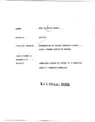
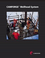
Bonnet Rebuild Softgoods KitsFor popular size U BOPs, a bonnet rebuild softgoods kit is available to provide all parts requiredto reseal the operating system.Kit parts are shrink-film packed to prevent loss and assure long shelf life. The kits areless expensive than individual parts. All parts in each kit are identified with part numbersand parts list index numbers.2434284233272629243231301821251920U BOP Bonnet Softgoods ComponentsSD 017515TC1001 22 © <strong>2002</strong> Cooper Cameron, Cameron Division
Kit Part NumbersBOP Size (in.) Pressure Rating/Bonnet Type Kit Part Number*7-1/16 3000, 5000, 10,000 and 15,000 psi All 644909-0111 3000, 5000, and 10,000 psi Pipe 644909-0211 15,000 psi All 644831-0813-5/8 3000, 5000, and 10,000 psi Pipe 644909-0313-5/8 15,000 psi All 644831-1216-3/4 5000 psi Pipe 644831-1416-3/4 10,000 psi All 644831-1518-3/4 10,000 psi All 644909-0420-3/4 3000 psi Pipe 644831-1721-1/4 2000 psi Pipe 644831-1821-1/4 5000 psi All 644831-1921-1/4 7500 psi All 644381-2021-1/4 10,000 psi Pipe 644831-2126-3/4 3000 psi All 644831-22*One kit contains softgoods for one bonnetU BOP Bonnet Rebuild Softgoods Kit ComponentsItem Number*Description18 Ring, Plastic Packing19 Ring, Plastic Energizing20 Seal Ring, Connecting Rod21 Ring, Backup24 O-Ring, Operating Cylinder25 O-Ring, Operating Piston Rod to Intermediate Flange26 Lip Seal, Operating Piston27 Seal Ring, Tail Rod28 O-Ring, Wiping29 O-Ring, Ram Change Piston to Body30 O-Ring, Ram Change Piston Rod to Intermediate Flange31 O-Ring, Ram Change Cylinder to Intermediate Flange32 O-Ring, Ram Change Piston to Bonnet33 O-Ring, Ram Change Piston34 O-Ring, Bonnet Bolt Retainer39 Packing, Plastic**42 Wear Ring, Operating Piston44 O-Ring (not shown)TC1001 23 © <strong>2002</strong> Cooper Cameron, Cameron Division
Drill Pipe Shearing RequirementsThe minimum shearing configurations needed for each size U BOP to meet the requirements ofthe second edition of API 16A are listed in the following chart. Each shearing configuration iscapable of shearing the corresponding pipe at a closing pressure equal to or less than 2800 psi.For further information on shearing requirements for different pipe sizes and grades, contactyour Cameron representative.API Designated Size Ram Type Pressure Rating (psi) Pipe OD (In.) Pipe lb/ft Pipe Grade Shearing Configuration7-1/16” SBR All 3-1/2 13.3 S Shear Bonnets with Tandem Boosters11” SBR 10,000 and Lower 5 19.5 E Shear Bonnets with Tandem Boosters11” DS/ISR 10,000 and Lower 5 19.5 E Large Bore Shear Bonnets11” SBR 15,000 and Higher 5 19.5 G Large Bore Shear Bonnets with Tandem Boosters13-5/8” SBR 10,000 and Lower 5 19.5 G Shear Bonnets with Tandem Boosters13-5/8” DS/ISR 10,000 and Lower 5 19.5 G Large Bore Shear Bonnets13-5/8” SBR 15,000 and Higher 5 19.5 S Large Bore Shear Bonnets16-3/4” SBR All 5 19.5 S Large Bore Shear Bonnets18-3/4” SBR All 5 19.5 S Standard Bonnets20-3/4” SBR 3000 and Lower 5 19.5 G Shear Bonnets with Tandem Boosters21-1/4” SBR 3000 and Lower 5 19.5 G Shear Bonnets with Tandem Boosters21-1/4” SBR 5000 and Higher 5 19.5 S Standard Bonnets21-1/4 SBR 10,000 and Higher 5 19.5 G Standard BonnetsLarge Bore Shear Bonnets12A**3A42A5A26A24A2ALarge Bore Shear RamBonnet AssemblySD-017503ItemNo.**2ADescription(2 Required perCavity)Bonnet Assembly(Right)Bonnet Assembly(Left)IntermediateFlange/Shear11”3000 psi Model II11”5000 psiModel II11”10,000 psiModel II11”15,000 psiModel 7913-5/8”3000 psiModel 1113-5/8”5000 psiModel II13-5/8”10,000 psiModel II13-5/8”15,000 psiModel B16-3/4”5000 psiModel B16-3/4”10,000 psiModel II20-3/4”3000 psiModel II21-1/4”2000 psiModel II615195-01 615194-01-00-01 614596-01-00-01 615419-01 615196-01 615191-01-00-01 614498-01-00-02 615540-01 615530-01 615537-01 615526-01 615525-01615195-02 615194-02-00-01 614596-02-00-01 615419-02 615196-02 615191-01-00-01 614498-02 615540-02 615530-02 615537-02 615526-02 615525-02615188-01 615188-01 615188-01 615459-01 615192-01 615192-01-00-01 614766-01-00-02 615538-01 615528-01 615535-01 615523-01 615523-013A Bonnet/Shear 615189-03 615189-02 615189-01 615640-01 615143-02 615143-01 614772-01 615448-01 615527-01 615534-01 615522-01 615522-025A24A26A42AOperatingPiston/ShearO-Ring, Int Flg toBonnet LipLip Seal,OperatingPiston/ShearWear Ring,OperatingPiston/Shear615190-02-00-01 615190-02-00-01 615190-02-00-01 615457-01 615209-01 615209-01-00-01 614760-01-00-02 615539-01 615529-01 615536-01 615524-01 615524-01702645-45-51 702645-45-51 702645-45-51 702645-45-81 702645-45-81 702645-45-81 702645-45-81 702645-46-51 702645-46-51 702645-46-51 702645-45-81 702645-45-81710586 710586 710586 710542 710542 710542 710542 710588 710588 710588 710542 710542049223-15 049223-15 049223-15 049223-04 049223-04 049223-04 049223-04 049223-17 049223-17 049223-17 049223-14 049223-14**Two shear bonnet assemblies, one right and one left, are required per cavity. The shear bonnet assembly consists of all items shown on the illustration.**See pages 17, 19 and 21 for bonnet bolt part numbers.TC1001 24 © <strong>2002</strong> Cooper Cameron, Cameron Division
Tandem Boosters for U BOPsA BOP equipped with tandem boosters can deliver increased shearing force while not increasingthe wear and tear on the packers. Tandem boosters approximately double theforce available to shear pipe. Since the tailrod of the tandem booster has the same strokeas the BOP’s operating piston, the standard shear locking mechanism can be installed onthe outside end of the booster. For information on lock screws and the required spacers,see pages 17, 19 and 21.For information concerning applications where a tandem booster is required, consultyour Cameron representative.21211139417 71016515143861Tandem Booster Assembly23SD-017504ItemNo.20-3/4” 3000 psi and21-1/4” 2000 psi7-1/16” 3000, 5000, 10,000 and 15,000 psi* 11’ 3000, 5000, and 10,000 psiDescriptionQty Part Number Qty Part Number Qty Part Number** Tandem Booster Assembly 1 645414-01 1 645219-01 1 645251-011 Cylinder 2 644959-01 2 645113-01 2 645113-042 Cylinder Head 2 645413-01 2 645171-01 2 645171-033 Piston 2 644961-01 2 2032370-02 2 645172-034 Tailrod 2 644962-01 2 645173-01 2 645173-045 Adapter Plate 2 644963-01 2 645115-01 2 645115-036 Screw, SDC HD Cap 16 018541-34 16 018542-13 16 K2504057 O-Ring 2 702645-24-91 2 702645-36-11 2 702645-37-118 Seal Ring 2 710541 2 712352 2 7105389 Wear Ring, Operating Piston 2 049223-03 2 049223-21 2 049223-0110 Filter, Muffler 2 710621 2 710621 2 71041711 Seal, Lip 2 212741-32 2 212741-33-00-01 2 212741-34-00-0112 Seal Ring 2 710620 2 712351 2 71041913 Wear Ring, Cylinder 2 644443-02 2 644443-03 2 645215-0114 Seal Ring 2 705955 2 712445 2 71041815 O-Ring 2 702645-33-11 2 702645-33-51 2 702645-33-7116 Alignment Ring 2 645116-02 2 645116-01 2 645116-0317 Pipe Plug 2 201018 2 201018 2 005930-05-1018 Connector, Tubing 1 675029-09 - - 4 204887-10-06-5719 Cross 1 006347-08 1 675029-52 2 675029-2320 Nipple, Pipe Regular 1 685904-06-00-30 1 685902-07-00-30 1 685902-07-00-3021 Hose Assembly 2 2708020 2 2708021 2 71137422 Connector, Tubing 2 678046-17 2 204887-10-05-56 - -23 Stud, Double End 16 219065-10-04-41 16 219065-12-05-01 - -24 Connector, Tubing 1 204888-08-05-56 - - - -25 Nipple, Pipe 1 685902-06-01 - - - -26 Connector, Tubing 1 675027-65 2 204887-10-06-56 - -27 Adapter, Pipe - - 2 675029-01 - -Repair Kit 2164148-01 2164148-03 2164148-02*The 7-1/16” tandem booster is a part of the standard land and platform shear configuration for 7-1/16” U BOPs.**One assembly includes two tandem boosters.TC1001 25 © <strong>2002</strong> Cooper Cameron, Cameron Division
Tandem Boosters for U BOPs942481061312SD 03459157233111514162171Item Number Description Qty11” 15,000 psi13-5/8” 3000, 5000 and 10,000 psi** Tandem Booster Assembly 1 2010886-011 Adapter Plate 2 2010885-012 Pipe Plug 2 2010881-013 Cylinder 2 2010884-014 Cylinder Head 2 2010882-015 Tail Rod 2 2010880-016 Piston 2 645172-037 Screw Cap 16 702585-31-00-308 Screw Cap 12 702585-34-01-649 O-Ring 2 702645-33-7110 Seal, Lip 2 212641-34-00-0111 O-Ring 2 702645-38-1212 Seal Ring 2 71041813 Wear Ring 2 645215-0114 Wear Ring 2 049223-0115 Seal Ring 2 70477216 Filter, Quiet Muffler 2 272404217 Stud, Double Ended 2 702533-09-10-2218 Connector, Tubing 2 204887-10-06-5719 Cross 1 675029-2320 Nipple, Pipe 1 685902-07-00-3021 Hose Assembly 2 272453822 Connector, Tubing 2 -23 Gland, Tubing 2 017454-0824 Blind Plug 2 017454-0925 Elbow 2 71440726 Pipe Plug 2 002504-28- Repair Kit - 2164148-02**One assembly includes two tandem boosters.TC1001 26 © <strong>2002</strong> Cooper Cameron, Cameron Division
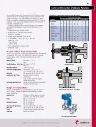
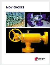
UM BOPsThe Cameron UM BOP is a lightweight blowout preventer designed for easy maintenanceand long life. The UM complements the existing line of U preventers with interchangeablebonnets that can be installed on any comparable size U BOP. Theshearing capabilities of the UM BOP bonnet is comparable to a U BOP bonnet withtandem boosters installed. The UM utilizes an internal booster that results in a reducedweight and length for the preventer and eliminates the need for externalplumbing. The UM replaces the UL since the UM bonnet features full stroke operationthat allows for one-step ram removal.Other features of the UM BOP include:• Bonnet seal carrier is available to eliminate the need for high makeup torqueon bonnet bolts and nuts.• Same bonnet used for both shear and pipe rams. The internal shear boostercan be reversed to act as a stroke-limiting device.• Internal booster provides the force necessary for shearing pipe and at thesame time provides a reduced sealing force for long ram seal life.• Hydraulically operated locking mechanisms, wedgelocks, are available forsubsea applications.• Most operating system seals can be replaced with the bonnet in theram-change position without removing the bonnets.• UM utilizes the same rams as the U BOP.Other features include hydraulically opening bonnets, forged body and a wide selectionof rams to meet all applications.UM Blowout PreventerSD 034595TC1001 27 © <strong>2002</strong> Cooper Cameron, Cameron Division
StandardTandemPipeBonnetPipeBonnetClosePressureOpenPressureClosePressureOpenPressureShearBonnetShearBonnetUM BOP Open and Close Hydraulics(13-5/8” 10,000 Shown)SD 034582TC1001 28 © <strong>2002</strong> Cooper Cameron, Cameron Division
UM BOP Operating Data and Fluid RequirementsBore Sizeand WorkingPressure7-1/16” AllWP11” Except15,000 psi11” 15,000psi13-5/8”Except15,000 psi13-5/8”15,000 psiModel BGals to OpenPipe Rams(1 set)Gals to ClosePipe Rams(1 set)Gals to CloseShear Rams(1 set)Closing Area(Sq. inches)Locking ScrewTurns(Each End)ClosingRatioOpeningRatio2.2 2.3 2.4 67.3 18 11.7:1 3.8:16.2 6.2 7.4 113.8 27 13.7:1 3.7:1- - - - - - -7.5 7.5 8.8 110.15 32 8.7:1 2.3:1- - - - - - -UM BOP Tandem Booster Operating Data and Fluid Requirements*Bore Sizeand WorkingPressure7-1/16” AllWP11” Except15,000 psi11” 15,000psi13-5/8”Except15,000 psi13-5/8”15,000 psiModel BGals to OpenShear Rams(1 set)Gals to CloseShear Rams(1 set)Closing Area(Sq. inches)Locking ScrewTurns(Each End)Closing RatioOpening Ratio- - - - - 3.8:17.4 13.1 201.8 27 24.3:1 3.7:1- - - - - -8.8 11.72 198 32 15.6:1 2.3:1- - - - - -*All volumes based on shear ram configurationTC1001 29 © <strong>2002</strong> Cooper Cameron, Cameron Division
TC1001 30 © <strong>2002</strong> Cooper Cameron, Cameron Division
UM BOP Specifications and DimensionsThe capital letters in the following designations refer to the UM BOP dimensional viewsand dimensional chart shown below .A-1 Length - bonnets closed, locking screws lockedA-2 Length - bonnets opened, locking screws unlockedB-1 Height - flangedB-2 Height - studdedC Width - no side outletsD Centerline of preventer to outlet flange or hub face. This distance is variableand must be determined per individual specifications.E Centerline of side outlet to bottom flange faceF Top of ram to top flange faceG Height of ramACDFBGESD 034610Single Open-Face Flange or Studded UM BOP Dimensions*SizePressureRating(psi)Vertical Bore(in)A-1 A-2 B-1 B-2 C E F GApprox.Weight (lb.)FlgXFlgApprox.Weight (lb.)StdXStd7-1/16” 3000 7-1/16 78.250” 116.500” 24.062” 17” 20.250” 8.750” 7.844” 5.50” 2600 24777-1/16” 5000 7-1/16 78.250” 116.500” 27.500” 16.75” 20.250” 10.406” 9.625” 5.50” 2652 24777-1/16” 10,000 7-1/16 78.250” 116.500” 30.562” 15.50” 20.625” 11.062” 12.031” 5.50” 3275 28257-1/16” 15,000 7-1/16 78.250” 116.500” 31.812” 15.50” 20.625” 11.688” 12.656” 5.50” 3525 282511” 10,000 11 96.250” 146.875” 35.688” 16.63” 25.750” 13.125” 13.844” 6.75” 6400 590013-5/8” 10,000 13-5/8 134.500” 201.000” 41.688” 20.26” 30.250” 15.125” 17.094” 7.50” 10,300 9650*Available with Stud x Flange ConnectionsTC1001 31 © <strong>2002</strong> Cooper Cameron, Cameron Division
UM BOP Specifications and DimensionsThe capital letters in the following designations refer to the UM BOP dimensional viewsand dimensional chart shown below.A-1 Length - bonnets closed, locking screws lockedA-2 Length - bonnets opened, locking screws unlockedB-1 Height - flangedB-2 Height - studdedB*** Height - with 30” spacerC Width - no side outletsD Centerline of preventer to outlet flange or hub face. This distance is variable andmust be determined per individual specifications.E Centerline of side outlet below rams to bottom flange faceF Top of upper ram to top flange faceG Height of ramH Centerline of side outlet between rams to bottom flange faceJ Top of lower ram to bottom of upper ramACDFGBJEHSD 034560Double Open-Face Flange or Studded UM BOP Dimensions*SizePressureRating(psi)Vertical Bore(in.)A-1 A-2 B-1 B-2 B*** C E F G H JApprox.Weight(lb.)FlgXFlgApprox.Weight(lb.)StdXStd7-1/16” 3000 7-1/16 78.250” 116.500” 41.000” 34” 18.562” 20.250” 8.750” 7.844” 5.50” 25.688” 11.438” 5100 49507-1/16” 5000 7-1/16 78.250” 116.500” 44.188” 33.50” 18.812” 20.250” 10.406” 9.625” 5.50” 27.094” 11.188” 4904 47297-1/16” 10,000 7-1/16 78.250” 116.500” 48.625” 31.50” 17.438” 20.625” 11.062” 12.031” 5.50” 29.125” 12.562” 5850 55007-1/16” 15,000 7-1/16 78.250” 116.500” 49.875” 33.50” 17.438” 20.625” 11.688” 12.656” 5.50” 29.750” 12.562” 6100 550011” 10,000 11 96.250” 146.875” 55.875” 36.44” 16.562” 25.750” 13.125” 13.844” 6.75” 33.312” 13.438” 11,300 11,30013-5/8” 10,000 13-5/8 134.500” 201.000” 66.625” 41.26” 12.562” 30.250” 15.125” 17.094” 7.50” 40.062” 17.438” 20,388 17,612*Available with Stud x Flange ConnectionsTC1001 32 © <strong>2002</strong> Cooper Cameron, Cameron Division
UM BOP Specifications and DimensionsThe capital letters in the following designations refer to the UM BOP dimensional viewsand dimensional chart shown below.A-1 Length - bonnets closed, locking screws lockedA-2 Length - bonnets opened, locking screws unlockedB-1 Height - flangedB-2 Height - studdedC Width - no side outletsD Centerline of preventer to outlet flange or hub face. This distance is variable andmust be determined per individual specifications.E Centerline of side outlet to bottom flange faceF Top of ram to top flange faceG Height of ramACDFGBESD 034612Single UM BOP with Tandem Boosters Dimensions*SizePressureRating(psi)Vertical Bore(in)A-1 A-2 B-1 B-2 C E F GApprox.Weight(lb.)FlgXFlgApprox.Weight(lb.)StdXStd13-5/8” 10,000 13-5/8” 169.125” 235.875” 41.688” 30.88” 30.50” 15.125” 17.094” 7.5” 11,600 11,000*Available with Stud x Flange ConnectionsTC1001 33 © <strong>2002</strong> Cooper Cameron, Cameron Division
37356343312331222640343353920382427282934334376352544121311 10 511514176766535256365021918162154551UM BOP, 7-1/16”SD 034510TC1001 34 © <strong>2002</strong> Cooper Cameron, Cameron Division
7-1/16” UM BOP Part NumbersItem No. Description Qty - Single Qty - Double7-1/16”5000 psiModel II7-1/16”10,000 psiModel II7-1/16”15,000 psiModel II1 Body 1 1 ---- ---- ----2 Bonnet 2 4 2010585-01 2010584-01 2010515-033 Operating Piston 2 4 2010559-02 2010559-01 2010559-014 Ram Change Piston, Open 2 4 2011075-01 2011075-01 2011075-015 Ram Change Piston, Close 2 4 2011073-01 2011073-01 2011073-016 Ram Change Cylinder 4 8 2011074-01 2011074-01 2011074-0110 Pin, Ram Guide 4 8 030313-02 030313-02 030313-0211 Check Valve 2 4 M517988 M517988 M51798812 Screw, Socket Head Set 2 4 005940-09 005940-09 005940-0913 Pipe Plug, Heavy Hex Head 2 4 005930-05-10 005930-05-10 005930-05-10*14 Retainer Ring, Plastic Packing 2 4 2010178-01 2010178-01 2010178-01*15 Energizing Ring 2 4 018586-12 018586-12 018586-12*16 Lip Seal 2 4 212741-37 212741-37 212741-37*17 O-Ring 2 4 018492-92 018492-92 018492-9218 Retainer, Lip Seal 2 4 689523-04 689523-04 689523-0419 Retaining Ring, Spirolox 2 4 018572-83 018572-83 018572-8320 Locking Screw 2 4 2010519-01 2010519-01 2010519-0121 Ring Gasket 4 8 ---- 021792-21 ----22 Locking Screw Housing 2 4 2010530-01 2010530-01 2010530-0123 Operating Cylinder 2 4 2010529-02 2010529-02 2010529-0224 Cylinder Head Weldment 2 4 2011328-01 2011328-01 2011328-0125 Stud, Double Ended 8 16 2010189-19 2010189-19 2010189-1926 Nut, Heavy Hex 8 16 2709000-13-01 2709000-13-01 2709000-13-01*27 Seal Ring 2 4 2708749-01 2708749-01 2708749-0128 Retainer Ring, Tail Rod 2 4 2010527-01 2010527-01 2010527-0129 Retaining Ring, Spirolox 2 4 041008-02-93-32 041008-02-93-32 041008-02-93-32*30 Seal Ring 2 4 2710280 2710280 2710280*31 O-Ring 4 8 702645-37-61 702645-37-61 702645-37-61*32 O-Ring 2 4 702645-26-91 702645-26-91 702645-26-91*33 Seal RIng 4 8 2724047 2724047 272404734 Wear Ring, Ram Change Piston 4 8 049223-28 049223-28 049223-28*35 O-Ring 8 16 702645-33-71 702645-33-71 702645-33-71*36 O-Ring 4 8 702645-32-81 702645-32-81 702645-32-81*37 O-Ring 8 16 702645-32-41 702645-32-41 702645-32-4138 Stud, Double Ended 16 32 219065-08-03-61 219065-08-03-61 219065-08-03-6139 Nut, Heavy Hex 16 32 2709000-08-01 2709000-08-01 2709000-08-0140 Lifting Eye 4 8 011849 011849 01184941 Split Retainer Ring 2 4 2010599-01 2010599-01 2010599-0142 Concentric Booster Ring 2 4 2010600-01 2010600-01 2010600-01*43 Seal Ring 2 4 710541 710541 710541*44 Plastic Packing 10 20 007650-08 007650-08 007650-0846 Blind Plug 4 8 017454-09 ---- 017454-0947 Pipe Plug 4 8 002504-04 ---- 002504-0448 Tubing Gland 4 8 017454-08 ---- 017454-0866 Name Plate 1 1 2032175-03 2032175-01 ----67 Name Plate 1 ---- 025950 025950 ----50 Bonnet Bolt 8 16 2010514-02 2010514-03 ----51 Bonnet Seal (Carrier Type) 4 8 ---- ---- ----51A Bonnet Seal (Face Type) 2 4 644197-01-00-01 644197-01-00-01 644197-01-00-0152 Stud, Double Ended 12 ---- ---- 219067-14-07-41 ----53 Nut, Heavy Hex 12 ---- ---- 2709000-14-01 ----54 Stud, Double Ended ---- ---- ---- ---- ----55 Nut, Heavy Hex ---- ---- ---- ---- ----56 Name Plate 1 1 ---- 236606-01 ----66 Name Plate 1 1 2032175-03 2032175-01 ----67 Name Plate 1 1 025950 025950 ----Accessory ItemsRam Change Piston Cover 2 4 645046-17 645046-17 645046-17Standard Accessory Items 1 1 697149-01 697149-02 697149-02Locking Screw Accessory Items 2 4 ---- 697150-01 697150-01Expendable ItemsRing Gasket 2 4 70<strong>2002</strong>-03-52 702003-15-22 702003-15-22Ring Gasket 2 4 70<strong>2002</strong>-04-62 702003-15-62 702003-15-62*These items included in Bonnet Rebuild Kit P/N 2010733-01. Two required for single, Four required for double.TC1001 35 © <strong>2002</strong> Cooper Cameron, Cameron Division
3533621232122263832285303313228435633173720362486 8725 40 422781062151417341115274 41 29121319181643UM BOP, 11”SD 034498TC1001 36 © <strong>2002</strong> Cooper Cameron, Cameron Division
11” UM BOP Part NumbersItem No. Description Qty - Single Qty - Double11”3000 psi11”5000 psi11”10,000 psi1 Body 1 1 ---- ---- ---- ----2 Bonnet (Seal Carrier) 2 4 ---- ---- ---- ----2A Bonnet (Face Seal) 2 4 ---- 2011152-01 2164126-01 ----3 Piston Subassembly 2 4 ---- 2011173-01 2011173-01 ----4 Ram Change Piston - Open 2 4 ---- 2011155-01 2011155-01 ----4A Ram Change Piston - Open, Special ---- ---- ---- ---- ---- ----5 Ram Change Piston - Close 2 4 ---- 2011144-01 2011144-01 ----5A Ram Change Piston - Close, Special ---- ---- ---- ---- ---- ----6 Ram Change Cylinder 4 8 ---- 2011154-01 2011154-01 ----8 O-Ring ---- ---- ---- ---- ---- ----9 Ram Change Piston Cap ---- ---- ---- ---- ---- ----10 Ram Guide Pin 4 8 ---- 030313-03 030313-03 ----11 Check Valve 2 4 ---- M517988 M517988 ----12 Set Screw, Socket Head 2 4 ---- 005940-09 005940-09 ----13 Pipe Plug 2 4 ---- 005930-05-10 005930-05-10 ----*14 O-Ring 2 4 ---- 2010178-02 2010178-02 ----*15 Energizing Ring 2 4 ---- 018586-13 018586-13 ----*16 Lip Seal 2 4 ---- 212741-38-00-01 212741-38-00-01 ----*17 O-Ring 6 12 ---- 018492-91 018492-91 ----18 Retainer, Lip Seal 2 4 ---- 689523-05 689523-05 ----19 Retaining Ring, Spirolox 2 4 ---- 018572-84 018572-84 ----20 Locking Screw 2 4 ---- 046628-01 046628-01 ----*21 O-Ring 4 8 ---- 702645-38-21 702645-38-21 ----22 Locking Screw Housing 2 4 ---- 2011168-01 2011168-01 ----23 Operating Cylinder 2 4 ---- 2011172-01 2011172-01 ----24 Cylinder Head Weldment 2 4 ---- 2011167-01 2011167-01 ----25 Stud, Double Ended 8 16 ---- 219065-17-20-01 219065-17-20-01 ----26 Nut 8 16 ---- 2164777-01 2164777-01 ----*28 O-Ring 4 8 ---- 702645-33-31 702645-33-31 ----*29 Plastic Packing 10 20 ---- 007650-25 007650-25 ----*30 Seal Ring 2 4 ---- 2724061 2724061 ----31 Wear Ring 2 4 ---- 049223-31 049223-31 ----32 Wear Ring 4 8 ---- 049223-32 049233-32 ----*33 O-Ring 8 16 ---- 702645-33-91 702645-33-91 ----*34 O-Ring 4 8 ---- 702645-33-01 702645-33-01 ----*35 O-Ring 8 16 ---- 702645-32-61 702645-32-61 ----36 Stud, Double Ended 16 32 ---- 219065-12-05-01 219065-12-05-01 ----37 Nut 16 32 ---- 2709000-12-01 2709000-12-01 ----38 Lifting Eye 2 4 ---- 011849 011849 ----40 Blind Plug 4 8 ---- 017454-09 017454-09 ----41 Plug, Pipe, Threaded 4 8 ---- 002504-04 002504-04 ----42 Tubing Gland 4 8 ---- 017454-08 017454-08 ----*43 Ring Gasket 4 8 ---- 021792-22 021792-22 ----52 Bonnet Bolt 8 16 ---- 2010962-01 2164128-01 ----62 Bonnet Seal Carrier 2 4 ---- 645464-02-00-01 645464-02-00-01 ----62A Bonnet Seal (Face Type) 2 4 ---- 644197-02-00-01 644197-02-00-01 ----62B Bonnet Seal (Carrier Type) 2 4 ---- 645484-02-00-01 645484-02-00-0162C Retainer Ring (Use with Seal Carrier) 2 4 ---- 702645-27-61 702645-27-6174 O-Ring 8 16 ---- 702645-22-91 702645-22-91 ----78 Lifting Eye 2 2 ---- 011849 011849 ----96 Name Plate 1 1 ---- 2032175-03 2032175-03 ----97 Name Plate 1 1 ---- 025950 025950 ----Accessory ItemsStandard Accessories 1 1 ---- 697149-02 697149-02 ----Locking Screw Accessories 2 4 ---- 697150-02 697150-02 ----Cover, Ram Change Pistons 2 2 ---- 645046-18 645046-18 ----Expendable ItemsRing Gaskets (Top & Bottom Conn.) 2 2 ---- 70<strong>2002</strong>-05-42 702003-15-82 ----*These items included in Bonnet Rebuild Kit P/N 2010733-02. Two required for single, Four required for double.11”15,000 psiTC1001 37 © <strong>2002</strong> Cooper Cameron, Cameron Division
392220459835537 36 63631233138 1529330 50 33 11 43 40 2141214 43 43 40 16 19 17 18 51 343244241112575747642 41 10 78See Detail“A”428127141211Detail “A”66656471702632111243431214UM BOP, 13-5/8”SD034538TC1001 38 © <strong>2002</strong> Cooper Cameron, Cameron Division
13-5/8” UM BOP Part NumbersItem No. Description Qty - Single Qty - Double13-5/8”13-5/8”13-5/8”5000 psi10,000 psi15,000 psi1 Body 1 1 ---- ---- ----2 Bonnet (Seal Carrier) 2 4 ---- 2164340-01(02) ----2A Bonnet (Face Seal) 2 4 ---- 2164343-01(02) ----3 Piston Subassembly (2) (4) ---- 2164345-01 ----4 Ram Change Piston - Open 2 4 ---- 2164433-02 ----4A Ram Change Piston - Open, Special 2 4 ---- 2164433-01 ----5 Ram Change Piston - Close 2 4 ---- 2164434-02 ----5A Ram Change Piston - Close, Special 2 4 ---- 2164434-01 ----6 Ram Change Cylinder 4 8 ---- 2164347-02 ----6A Ram Change Cylinder, Special 4 8 ---- 2164347-01 ----*8 O-Ring 4 8 ---- 702645-35-71 ----9 Ram Change Piston Cap 4 8 ---- 2164342-02 ----9A Ram Change Piston Cap, Special 4 8 ---- 2164342-01 ----10 Ram Guide Pin 4 8 ---- 030313-01 ----11 Retainer Ring, Spirolox, Operating Piston 8 16 ---- 708758 ----12 Retainer, Polypak 8 16 ---- 689523-06 ----*14 Seal Polypak 8 16 ---- 2724613-01 ----*15 Wear Ring, Ram Change Piston 4 8 ---- 2164449-01 ----16 Check Valve 2 4 ---- M517988 ----17 Screw, Socket Head 2 4 ---- 005940-09 ----18 Pipe Plug 2 4 ---- 005930-05-10 ----*19 Packing, Plastic 2 4 ---- 007650-25 ----20** Locking Screw 2 4 ---- 695234 ----22** Locking Screw Housing 2 4 ---- 2164346-01 ----23 Operating Cylinder 2 4 ---- 2164348-02 ----23 Operating Cylinder, Special 2 4 ---- 2164348-01 ----24 Cylinder Head 2 4 ---- 2164341-02 ----24 Cylinder Head, Special 2 4 ---- 2164341-01 ----25 Cylinder Stud 24 48 ---- 2164361-01 ----26 Nut, Cylinder 24 48 ---- 2709000-12-22 ----*27 Retainer Ring, Plastic Packing 2 4 ---- 012469-24 ----*28 Energizing Ring 2 4 ---- 018586-01 ----*29 Wear Ring, Operating Piston 2 4 ---- 049223-31 ----*30 Seal Ring 2 4 ---- 2724061 ----*31 O-Ring 4 8 ---- 702645-38-21 ----32 Washer, Cylinder Stud 24 48 ---- K220607 ----33 Washer, Bonnet Bolt 8 16 ---- 2164450-01 ----*35 O-Ring 4 8 ---- 702645-33-81 ----*36 O-Ring 8 16 ---- 702645-34-61 ----*37 O-Ring 8 16 ---- 702645-32-41 ----37A O-Ring, Special for V Threaded Ram Change Piston 8 16 ---- 702645-32-81 ----*38 O-Ring 4 8 ---- 702645-33-31 ----39** Screw 16 32 ---- 702585-25-00-30 ----40 Lifting Eye 4 8 ---- 011849 ----41 Tubing Gland 4 8 ---- 017454-08 ----42 Blind Plug 4 8 ---- 017454-09 ----43 Pipe Plug, Pressure 12 24 ---- 002504-14 ----45 Pipe Plug, Threaded 4 8 ---- 203682 ----50 Bonnet Bolt 8 16 ---- 2164362-01 ----*51 O-Ring 8 16 ---- 2164718-01 ----64 Name Plate 1 1 ---- 025950 ----65 Name Plate 1 1 ---- 2032175-03 ----66 Name Plate 1 1 ---- 236606-01 ----70 Lifting Lug 2 2 ---- 2164420-01 ----71 Screw, Cap 8 8 ---- 702546-31-00-34 ----74 Stud, Top End Connection 20 20 ---- 219065-17-10-71 ----75 Nut, Top End Connection 20 20 ---- 2709000-17-01 ----76 Pipe Plug 2 4 ---- 201019 ----77 Bonnet Seal Carrier 2 4 ---- 645507-01-00-01 ----78 Bonnet Seal (for Carrier) 4 8 ---- 645509-01-00-01 ----78A Bonnet Seal (Face Type) (2) (4) ---- 644197-03-00-01 ----78B Retainer Ring (Use with Seal Carrier) 2 4 ---- 702645-27-9179 O-Ring 2 4 ---- 702645-56-91 ----80*** Tandem Booster Assembly (Qty. 1 for 2 Bonnets) 1 1 ---- 2164649-01 ----Accessory ItemsStandard Accessories 1 1 ---- 697149-12 ----Locking Screw Accessories 2 4 ---- 697150-02 ----Spanner Wrench 1 1 ---- 2164429-01 ----Expendable ItemsRing Gaskets (Top & Bottom Connection) 2 2 ---- 702003-15-92 ----Eyebolt 2 2 ---- 700734 ----Paste 1 1 ---- 705444 ----Loctite Adhesive 1 1 ---- 708740 ----Thread Sealant 1 1 ---- 711706 ----*These items included in Bonnet Rebuild Kit P/N 2010733-03. Two required for single, Four required for double.**Not Required When Using Wedgelocks or Tandem Boosters***Optional Tandem BoostersTC1001 39 © <strong>2002</strong> Cooper Cameron, Cameron Division
Minimum Shearing Configurations for the UM BOPAPI Designated Size Ram Type Pressure Rating (psi) Pipe OD (In.) Pipe lb/ft Pipe Grade Shearing Configuration7-1/16” SBR All 3-1/2 13.3 S Standard Bonnets11” SBR 10,000 and Lower 5 19.5 E Shear Bonnets with Tandem Boosters11” DS 10,000 and Lower 5 19.5 E Standard Bonnets13-5/8” SBR 10,000 and Lower 5 19.5 G Standard Bonnets13-5/8” DS 10,000 and Lower 5 19.5 G Standard BonnetsNote: See page 41 for a complete list of part numbers for the tandem boosters.161771512131415631123249108254282730292629Tandem Booster AssemblySD 034536TC1001 40 © <strong>2002</strong> Cooper Cameron, Cameron Division
Tandem Boosters for UM BOPsA BOP equipped with tandem boosters can deliver increased shearing force whilenot increasing the wear and tear on the packers. Tandem boosters approximatelydouble the force available to shear pipe. Since the tailrod of the tandem booster hasthe same stroke as the BOP’s operating piston, the standard shear locking mechanismcan be installed on the outside end of the booster.For information concerning applications where a tandem booster is required, consultyour Cameron representative.13-5/8” 10,000 psi WP UM Tandem BoosterItem Number Description Qty.1 Adapter 2 2164650-01Part Number13-5/8” 10,000 psi WP3 Cylinder 2 2010884-014 Cylinder Head 2 2010882-025 Tail Rod 2 2010880-016 Piston 2 645172-037 Screw, 12 Pt Cap 16 702585-25-00-308 Screw, 12 Pt Cap 12 702585-34-01-549 O-Ring 2 702645-33-7110 Seal, Lip 2 011741-3411 O-Ring 2 702645-38-1212 Seal Ring 2 71041813 Wear Ring 2 645215-0114 Wear Ring 2 049223-0115 Seal Ring 2 70477216 Filter, Muffler, Quiet Flow 2 272404217 Stud, Continuous Thread 2 702533-09-10-2223 Gland, Tubing 2 017454-0824 Blind Plug 2 017454-0925 Plug, Pipe-Threaded Hex Socket 2 002504-2826 Tubing, Hydraulic 2 2711865-12-1127 Bushing, Pipe 2 K19448928 Bushing, Pipe 2 20309829 Connector, Tubing, Male 4 204887-08-05-1730 Elbow, 90 Degree, Male 2 204890-08-05-17TC1001 41 © <strong>2002</strong> Cooper Cameron, Cameron Division
U and UM BOP Standard AccessoriesU and UM BOP Standard AccessoriesSize and Working PressureRamLube*CameronBox Wrench*Allen Wrench*Packing Screw Handwheel** UniversalJoint**ExtensionWrench*7-1/16” 3000 psi 713878 713114-08 008721-01 005457 006018-01 0056527-1/16” 5000 psi 713878 713114-08 008721-01 005457 006018-01 0056527-1/16” 10,000 & 15,000 psi 713878 713114-10 008721-01 005457 006018-01 00565211” 3000, 5000 & 10,000 psi 713878 713114-10 008721-01 005298 006018-03 00552611” 15,000 psi 713878 713114-13 008721-01 005298 006018-03 00552613-5/8” 3000 & 5000 psi 713878 713114-10 008721-01 005298 006018-03 00552613-5/8” 10,000 psi 713878 713114-13 008721-01 005298 006018-03 00552613-5/8” 15,000 psi 713878 *** 008721-01 005298 006018-03 00552616-3/4” 3000 & 5000 psi 713878 713114-13 008721-01 005298 006018-03 00552616-34/4” 10,000 psi 713878 *** 008721-01 005298 006018-03 00552618-3/4” 10,000 psi 713878 *** 008721-01 005298 006018-03 00552620-3/4” 3000 psi 713878 713114-08 008721-01 005298 006018-03 00552621-1/4” 2000 psi 713878 713114-10 008721-01 005298 006018-03 00552621-1/4” 5000 psi 713878 *** 008721-01 005298 006018-03 00552621-1/4” 10,000 psi 713878 *** 008721-01 005298 006018-03 00552626-3/4” 3000 psi 713878 713114-13 008721-01 005298 006018-03 005526*One required.**Two required for single preventer, four for double preventer.*** Commercially available sockets are recommended.TC1001 42 © <strong>2002</strong> Cooper Cameron, Cameron Division
U, UL and UM BOP Pipe RamsPipe rams are available for use in Cameron U, UL and UM BOPs to fit all commonly usedsizes of tubing, drill pipe, drill collar or casing within the ranges in the charts on the followingpages. Cameron pipe rams include the following features:• Cameron pipe rams are self-feeding and incorporate a large reservoir ofpacker rubber to ensure a long-lasting seal under all conditions.• Ram packers lock into place and are not dislodged by well flow.• All Cameron pipe rams are suitable for H 2 S service per NACE MR-01-75.• CAMRAM top seals are standard for all U, UL and UM BOP pipe rams from7-1/16” through 18-3/4” sizes. Packer part numbers beginning with 644xxxindicate the CAMRAM lipped-plate design. Other part numbers may usestandard elastomer material and reinforced plates. Verify this with yourCameron representative.CAMRAM 350 packers and top seals are available for high temperature service and forservice in which concentrations of H 2 S are expected.U, UL and UM BOP Pipe RamTC1001 43 © <strong>2002</strong> Cooper Cameron, Cameron Division
Part Numbers for U, UL & UM BOP Pipe RamsPipe Size(in.)7-1/16”3000, 5000, 10,000, and 15,000 psi WPTop Seal 644214-01-00-0111”3000, 5000, and 10,000 psi WPTop Seal 644217-01-00-0111”15,000 psi WPTop Seal 2010453-0113-5/8”3000, 5000, and 10,000 psi WPTop Seal 644223-01-00-01Assembly Ram Packer Assembly Ram Packer Assembly Ram Packer Assembly Ram PackerBlind 644504-01 644500-01-00-02 644215-01-00-01 644219-01 044118-01 644218-01-00-01 644222-01 044121-01 644221-01 644225-01 044147-01-00-01 644224-01-00-011.050 644504-02 644501-01 644215-02 - - - - - - - - -1.315 644504-03 644501-02 644215-03 044233-25 044118-07 019243-08 - - - 644225-02 044148-06 644224-021.660 644504-04 644501-03 644215-04-00-01 044233-02 044118-02 019243-06 644222-02 044121-02 644221-02 644225-03 044148-05 644224-031.900 644504-05 644501-04 644215-05-00-01 044233-03 044118-03 019243-05 644222-03 044121-03 644221-03 644225-04 044148-07 644224-042.062 644504-06 644501-05 644215-06 044233-04 044118-04 019243-04 644222-04 044121-04 644221-04 644225-05 044148-03 644224-052.375 644504-07 644501-06 644215-07-00-01 644219-06 044118-05 644218-06-00-01 644222-05 044121-05 2010454-05 644225-06 044148-01-00-01 644224-06-00-012.875 644504-08 644501-07 644215-08-00-01 644219-07 044118-06 644218-07-00-01 644222-06 044121-06 2010454-06 644225-07 044148-02-00-01 644224-07-00-013.500 644504-09 644502-01-00-01 644215-09-00-01 644219-08 644835-01-00-02 644218-08-00-01 644222-07 644753-01 2010454-07 644225-08 644738-01-00-01 644224-08-00-014.000 644504-11 644503-02 644215-11-00-01 644219-10 044119-02 644218-10-00-01 044234-10 044122-04 644218-13 644225-10 044149-02 644224-10-00-014.500 644504-12 644503-03 644215-12-00-01 644219-11 644835-02 644218-11-00-01 644222-09 644753-02 2010454-09 644225-11 644738-02 644224-11-00-014.750 - - - 044233-12 044119-04 644218-13 - - - 644225-13 044150-01 644224-135.000 644504-14 644503-05 644215-14-00-01 644219-14 644835-03-00-01 644218-14-00-01 644222-10 644753-03 2010454-10 644225-14 644738-03-00-01 644224-14-00-015.500 644504-15 644503-06 644215-15-00-01 644219-16 044120-01 644218-16-00-01 044234-13 044123-01 2010454-11 644225-16 044150-03 644224-16-00-015.750 - - - 044233-23 044120-10 644218-17 - - - - - -5.875 - - - - - - - - - 644225-30 644738-06-00-01 644224-29-00-016.000 - - - 044233-16 044120-02 644218-18-00-01 044234-14 044123-02 690808-13 044244-13 044150-04 644224-176.625 - - - 044233-17 644835-04 644218-19-00-01 044234-15 044123-03 690808-14 644225-18 644738-04-00-02 644224-18-00-017.000 - - - 044233-18 044120-04 644218-20-00-01 044234-16 044124-01 2010454-14 644225-19 044151-01-00-01 644224-19-00-017.625 - - - 044233-19 044120-05 644210-21-00-01 044234-17 044124-02 690808-16 644225-20 044151-02 644224-20-00-017.750 - - - 044233-22 044120-09 644218-22-00-01 - - - 044244-25 044151-06 644224-218.625 - - - 044233-20 044120-06 644218-23-00-01 - - - 044244-16 044151-03 644224-229.000 - - - - - - - - - 044244-24 044151-04 019506-069.625 - - - - - - - - - 644225-24 044151-05-00-01 644224-24-00-0110.750 - - - - - - - - - 644225-25 044152-01 644224-25-00-0111.750 - - - - - - - - - 044244-26 614208-01 644224-26-00-013.500Aluminum4.500Aluminum5.000Aluminum644504-10 644503-01 644215-10 044233-08 044119-06 644218-09 - - - 044244-20 044149-04 644224-09644504-13 644503-04 644215-13 044233-11 044119-07 644218-12 - - - 044244-10 044149-05 031215-17- - - 044233-24 044119-08 644218-15 - - - 044244-32 044150-08 031215-27TC1001 44 © <strong>2002</strong> Cooper Cameron, Cameron Division
Part Numbers for U, UL & UM BOP Pipe RamsPipe Size(in.)13-5/8”15,000 psiTop Seal 644226-01-00-0116-3/4”3000, 5000, and 10,000 psiTop Seal 644229-01-00-0118-3/4”10,000 psiTop Seal 644232-01-00-0121-1/4”5000 and 10,000 psiTop Seal 2010939-01Assembly Ram Packer Assembly Ram Packer Assembly Ram Packer Assembly Ram PackerBlind 644228-01 044143-01 644227-01-00-01 644231-01 044179-01 644230-01-00-01 644234-01 044184-01 644233-01 044262-01 044214-01 2010851-191.050 - - - - - - - - - - - -1.315 - - - - - - - - - - - -1.660 - - - - - - - - - - - -1.900 - - - 644231-02 044180-03 644230-02-00-01 - - - - - -2.062 044243-02 044144-03 040910-20 - - - - - - - - -2.375 644228-03 044144-01 644227-03-00-01 644231-03 044180-01 644260-03 044254-02 044185-01 644233-02 044262-02 044215-01 2010851-012.875 644228-04 044144-02 644227-04-00-01 644231-04 044180-02 644230-04 044254-03 044185-02 644233-03 044262-03 044215-02 2010851-023.500 644228-05 644739-01 644227-05-00-01 644231-05 644740-01 644230-05-00-01 644234-04 644741-01 644233-04-00-01 44262-04 644743-01 2010851-034.000 644228-07 044144-06 644227-07 644231-06 044181-02 644230-06 044254-06 044185-05 644233-06 044262-06 044215-05 040962-044.500 644228-08 644739-02 644227-08-00-01 644231-07 644740-02 644230-07-00-01 044254-07 644741-02 644233-07 044262-07 644743-02 2010851-054.750 044243-10 044145-01 040910-07 644231-08 044181-04 644230-08-00-01 044254-09 044185-08 041856-06 044262-09 044215-08 040962-065.000 644228-11 644739-03 644227-11-00-01 644231-09 644740-03 644230-09-00-01 644234-10 644741-03 644233-10-00-01 044262-10 644743-03 2010851-075.500 044243-12 044145-03 644227-12-00-01 644231-10 044181-06 644230-10-00-01 044254-11 044185-10 644233-11 044262-11 044215-10 2010851-085.750 - - - - - - - - - - - -5.875 2164172-07 2724029-06 644227-24-00-01 644231-22 2724030-06 644230-23 644234-21 2724031-06 644233-21-00-01 044262-32 2724033-06 2010851-296.000 044243-14 044145-04 040910-09 644231-11 049291-01 644230-11 044254-13 044185-12 041856-09 044262-13 044215-12 040962-096.625 044243-15 644739-04 644227-14 644231-12 049291-02 644230-12 044254-14 044185-13 644233-13 044262-14 044215-13 2010851-107.000 044243-16 044146-01 644227-15-00-01 644231-13 049291-03 644230-13 044254-15 044185-14 644233-14 044262-15 044215-14 2010851-117.625 044243-17 044146-02 644227-16-00-01 644231-14 049291-04 644230-14 044254-16 044185-15 041856-12 044262-16 044215-15 040962-127.750 044243-22 044146-07 644227-17 - - - - - - - - -8.625 044243-18 044146-03 040910-13 644231-15 049291-06 644230-15-00-01 044254-17 044185-16 041856-13 044262-17 044215-16 040962-139.000 044243-19 044146-04 040910-14 644231-16 049291-07 644230-16-00-01 044254-18 044185-17 041856-14 044262-18 044215-17 040962-149.625 044243-20 044146-05 644227-20-00-01 644231-17 049292-01 644230-17-00-01 044254-19 044185-18 644233-18 044626-19 044215-18 040962-1510.750 044243-21 044146-06 644227-21-00-01 644231-18 049292-02 644230-18-00-01 044254-21 044185-21 644233-19 044262-20 044216-01 040962-2011.750 - - - 644231-19 049292-03 644230-19-00-01 - - - 044262-21 044216-02 2010851-2013.375 - - - 644231-20 049292-04 644230-20-00-01 044254-22 044185-20 644233-20 044262-22 044216-03 2010851-2213.625 - - - - - - - - 044262-24 044216-05 040962-2413.750 - - - - - - - - - - - -16.000 - - - - - - - - - 044262-23 044216-04 2010851-233.500Aluminum4.500Aluminum5.000Aluminum044243-06 044144-05 644227-06 - - - 044254-05 044185-04 041856-16 044262-05 044215-04 040962-16044243-08 044144-08 040910-05 - - - 044254-08 044185-07 041856-17 044262-08 044215-07 040962-17- - - - - - - - - - - -TC1001 45 © <strong>2002</strong> Cooper Cameron, Cameron Division
Part Numbers for U, UL & UM BOP Pipe RamsPipe Size(in.)21-1/4” Bore 2000 psi20-3/4” Bore 3000 psiTop Seal 2163621-0126-3/4” Bore2000 and 3000 psiTop Seal 2163566-01Assembly Ram Packer Assembly Ram PackerBlind 044256-01 044191-01 2163612-01 044260-01 044209-01 2163561-011.050 - - - - - -1.315 - - - - - -1.660 - - - - - -1.900 - - - - - -2.062 - - - - - -2.375 - - - 044260-02 614017-01 2163559-012.875 - - - 044260-03 614017-02 2163559-023.500 044256-02 645328-01 2163613-03 044260-04 614018-01 2163599-034.000 044256-03 044192-02 031228-04 044260-05 614018-02 2163599-044.500 044256-04 645328-02 2010583-05 044260-06 614018-03 2163599-054.750 044256-05 044192-04 031228-06 - - -5.000 044256-06 645328-03-00-01 2163613-06 044260-07 614018-04 2163599-065.500 044256-07 044193-02 2163613-07 044260-08 614018-05 2163599-075.750 - - - - - -5.875 044256-32-00-01 645328-05-00-01 2163613-18 - - -6.000 044256-08 044193-03 031228-09 044260-09 614019-01 2163559-086.625 044256-09 645328-04 2010583-10-01 044260-10 614019-02 2163559-097.000 044256-10 044193-05 031228-11 044260-11 614019-03 2163559-107.625 044256-11 044193-06 031228-12 044260-12 614019-04 2163559-017.750 - - - - - -8.625 044256-13 044193-08 031228-14 - - -9.000 044256-14 044193-09 031228-15 044260-14 614019-06 2163599-139.625 044256-15 044193-10 031228-16 044260-15 614020-01 2163599-1410.750 044256-16 044194-01 2010583-17 044260-16 614020-02 2163599-1511.750 044256-17 044194-02 031228-18 044260-17 614020-03 2163599-1613.375 044256-18 044194-03 2163613-15 044260-18 614020-04 2163599-1713.625 044256-21 044194-05 031228-24 - - -13.750 044256-19 044194-04 031228-19 - - -16.000 044256-20 044195-01 2010583-21 044260-19 614021-01 2163559-1818.625 044256-22 614459-01 031228-25 - - -20.000 - - - 044260-20 614021-02 2163559-21TC1001 46 © <strong>2002</strong> Cooper Cameron, Cameron Division
Hang-Off WeightsHang-off weights are estimated capacities with hardened top corners of the hang-off rams. This enablesthe rams to dig into the tool joint and provide superior hang-off capacity while still meetingNACE requirements.For variable bore rams (VBR’s) and FLEXPACKER rams hang-off data, refer to Cameron EngineeringBulletin 859D.Hang-Off Weights(See Cameron Engineering Bulletin 636)Pipe SizePipe Rams3-1/2” 425,000 lb4-1/2” 550,000 lb5” 600,000 lb5-1/2” 600,000 lb6-5/8” 600,000 lbU BOP Shearing Blind RamsCameron shearing blind rams shear the pipe in the hole, then bend the lower section of sheared pipeto allow the rams to close and seal. Shearing blind rams can be used as blind rams during normaldrilling operations.The DS shearing blind ram can cut large diameter tubulars or multiple tubing strings regardless oftheir orientation to the centerline of the ram. A blade seal between the upper and lower faces eliminatesthe need for moving pipe after shearing.Features of shearing blind rams and DS rams include:• Large frontal area on the blade face seal reduces pressure on the rubber and increases servicelife.• Cameron SBRs can cut pipe numerous times without damage to the cutting edge.• The single-piece body incorporates an integrated cutting edge.• CAMRAM TM top seals are standard for all U BOP shearing blind rams through 18-3/4”.• For U and UII BOPs through 18-3/4”, part numbers beginning with 644XXX indicate theCAMRAM lipped-plate design. Other part numbers may use standard elastomer material andreinforced plates. Verify this with your Cameron representative.• H 2 S SBRs are available for critical service applications and include a blade material ofhardened high alloy suitable for H 2 S service.TC1001 47 © <strong>2002</strong> Cooper Cameron, Cameron Division
Shearing Blind RamU, UL and UM BOP Shearing Blind Ram Part NumbersBOP Bore Size andWorking Pressure7-1/16” 5000,10,000, 15,000 psi1Upper Ram Subassy2Body*Description and Item Number3Blade Packer*4Side Packer*5Side Packer*046792-01-00-03 046210-01-00-04 - 2010873-02 2010873-0111” 5000, 10,000 psi 645011-03-00-01 645009-01-00-01 046910-04-00-01 046751-04-00-01 046752-04-00-0111” 15,000 psi 2010458-01 2010459-01 046910-04-00-01 2010460-07 2040461-0713-5/8” 5000,10,000 psi644781-01-00-01 644780-01-00-01 644435-01-00-01 046751-01-00-02 046752-01-00-0213-5/8” 15,000 psi 2163019-01-01 2163017-01-01 644435-01-00-01 046751-05-00-01 046752-05-00-0116-3/4” 5000 psi 046766-01-00-01 049006-01-00-01 046910-03-00-01 046751-03-00-01 046752-03-00-0116-3/4” 10,000 psi 046773-01-00-01 046774-01-00-01 046910-03-00-01 046751-03-00-01 046752-03-00-0118-3/4” 10,000 psi 2010186-01 2010187-01 2010192-01 2010191-01 2010190-0120-3/4” 3000 psi 046783-01-00-02 046784-01-00-02 - 615235-01-00-01 -21-1/4” 2000 psi 046783-01-00-02 046784-01-00-02 - 615235-01-00-01 -21-1/4” 5000 psi 049983-01 049961-01 046910-05-00-01 046751-06-00-01 046752-06-00-0121-1/4” 7500,10,000 psi046788-01 049012-01 046910-05-00-01 046751-06-00-01 046752-06-00-01BOP Bore Size andWorking Pressure7-1/16” 5000,10,000, 15,000 psi6Lower Ram Subassy**7BodyDescription and Item Number8Side Packer9Side Packer10Top Seal(2 Required)046792-02-00-03 046212-01-00-04 2010672-01 - 644214-01-00-0111” 5000, 10,000 psi 645011-04-00-01 645009-02-00-01 046751-04-00-01 046752-04-00-01 644217-01-00-0111” 15,000 psi 2010458-02 2010459-02 2010460-07 2010461-07 2010453-0113-5/8” 5000,10,000 psi644781-02-00-01 644780-02-00-01 046751-01-00-02 046752-01-00-02 644223-01-00-0113-5/8” 15,000 psi 2163019-02-01 2010292-01 046751-05-00-01 046752-05-00-01 644226-01-00-0116-3/4” 5000 psi 046766-02-00-01 049007-01-00-01 046751-03-00-01 046752-03-00-01 644229-01-00-0116-3/4” 10,000 psi 046773-02-00-01 046775-01-00-01 046751-03-00-01 046752-03-00-01 644229-01-00-0118-3/4” 10,000 psi 2010186-02 2010188-01 2010191-01 2010190-01 2010193-0120-3/4” 3000 psi 046783-02-00-02 046785-01-00-02 615247-01-00-01 615247-02-00-01 2163621-0121-1/4” 2000 psi 046783-02-00-02 046785-01-00-02 615247-01-00-01 615247-02-00-01 2163621-0121-1/4” 5000 psi 049983-02 049982-01 046751-06-00-01 046752-06-00-01 645478-01-00-0121-1/4” 7500,10,000 psi046788-02 049011-01 046751-06-00-01 046752-06-00-01 645478-01-00-01*Part of Upper Ram Assembly.TC1001 48 © <strong>2002</strong> Cooper Cameron, Cameron Division
H 2 S Shearing Blind RamU, UL and UM BOP H 2 S Shearing Blind Ram Part NumbersBOP Bore Sizeand WorkingPressure (psi)11” 5000 and10,0001Upper RamSubassy2Ram3Blade Packer4Packer5Packer6Top Seal7Blade Insert8Set Screw645011-03-00-01 645009-01-00-01 046910-04-00-01 046751-04-00-01 046752-04-00-01 644217-01-00-01 645010-01-00-01 644582-0113-5/8” 5000 and10,000644781-01-00-01 644780-01-00-01 644435-01-00-01 046751-01-00-02 046752-01-00-02 644223-01-00-01 644581-01-00-01 644582-0113-5/8” 15,000 2163019-01-01 2163017-01-01 644435-01-00-01 046751-05-00-01 046752-05-00-01 644226-01-00-01 216481-01 644582-0118-3/4” 10,000 2010186-01 2010187-01 2010192-01 2010191-01 2010190-01 2010193-01 2010182-01 644524-01BOP Bore Sizeand WorkingPressure (psi)11” 5000 and10,00013-5/8” 5000 and10,0009Lower RamSubassy10Ram11Packer12Packer13Top Seal14Blade Insert645011-04-00-01 645009-02-00-01 046751-04-00-01 046752-04-00-01 644217-01-00-01 645010-02-00-01 <strong>2002</strong>31644781-02-00-01 644780-02-00-01 046751-01-00-02 046752-01-00-02 644223-01-00-01 644581-02-00-01 <strong>2002</strong>3113-5/8” 15,000 2163019-02-01 2163018-01-01 046751-05-00-01 046752-05-00-01 644226-01-00-01 644581-02-00-01 <strong>2002</strong>3118-3/4” 10,000 2010186-02 2010188-01 2010191-01 2010190-01 2010193-01 2010183-01 <strong>2002</strong>3115PinSevere Service U, UL and UM BOP H 2 S Shearing Blind Ram Part NumbersBOP Bore Sizeand WorkingPressure (psi)13-5/8” 5000 and10,0001Upper RamSubassy2Ram3Blade Packer4Packer5Packer6Top Seal7Blade Insert8Set Screw644781-03-00-01 644780-01-00-01 644834-01-00-01 645427-01-00-01 645428-01-00-01 644707-01-00-01 644581-01-00-01 644582-0113-5/8” 15,000 2163019-01-02 2163017-01-01 644834-01-00-01 644832-01-00-01 644833-01-00-01 644709-01-00-01 2164281-01 644582-01BOP Bore Sizeand WorkingPressure (psi)13-5/8” 5000 and10,0009Lower RamSubassy10Ram11Packer12Packer13Top Seal14Blade Insert644781-04-00-01 644780-02-00-01 645427-01-00-01 645428-01-00-01 644707-01-00-01 644581-02-00-01 <strong>2002</strong>3113-5/8” 15,000 2163019-02-02 2163018-01-01 644832-01-00-01 644833-01-00-01 644709-01-00-01 644581-02-00-01 <strong>2002</strong>3115PinTC1001 49 © <strong>2002</strong> Cooper Cameron, Cameron Division
DS Shearing Blind RamU BOP DS Shearing Blind RamBOP Size andWorkingPressure (psi)11” 5000 and10,00013-5/8” 5000 and10,000BOP Size andWorkingPressure (psi)11” 5000 and10,00013-5/8” 5000 and10,0001Upper RamAssembly2*BodyDescription and Item Number3*SidePacker4*SidePacker5*BladeSeal6*BladeSeal645078-01-00-04 645079-01-00-04 645080-02-00-01 645080-01-00-01 645031-02-00-01 645031-02-00-01645026-01-00-04 645027-01-00-04 2010985-01 2010985-02 2010986-01 2010986-027Lower RamSubassembly8**Body9**SidePacker10**SidePacker11Top Seal(2 Required)645078-02-00-04 645079-02-00-04 645080-02-00-01 645080-01-00-01 644217-02-00-01645026-02-00-04 645027-02-00-04 2010985-01 2010985-02 6445033-01-00-01*Part of Upper Ram Subassembly. Item 6 not shown.TC1001 50 © <strong>2002</strong> Cooper Cameron, Cameron Division
ISR Shearing Blind RamInterlocking Shear Ram (ISR) is available for the U type BOP line. The ISR rams provide an improvedshearing capacity alternative to the standard SBR rams, and should only be used when the standardrams cannot handle the desired shearing load. Since the geometry of the ISR ram incorporates a “V”shape and is designed as wide as possible, it can shear multiple strings and drill pipe as large as 6-5/8”OD. Also, ISR rams do not have to fold over the lower fish. This means less force is required to shearand, by leaving the fish open, kill mud can be pumped down the severed drill string. The interlockingmechanism incorporated in the ISR means that these rams can be utilized in an oversized cavity withoutfear of a leak at low wellbore pressures.1012574923116SD 034603U and UM BOP ISR Shearing Blind RamBOP Bore Sizeand WorkingPressure (psi)13-5/8”3000, 5000 and10,000BOP Bore Sizeand WorkingPressure (psi)13-5/8”3000, 5000 and10,0002-7Upper RamSubassembly2Body3SidePackerDescription and Item Number4SidePacker5TopSeal6BladeSeal7BladeSeal2164775-01 2164773-01 2010985-01 2010985-02 6445033-01-00-01 2010986-01 2010986-029-14Lower RamSubassembly9Body10SidePacker11SidePacker12TopSeal13*BladeSeal14*BladeSeal2164776-01 2164774-01 20101985-01 2010985-02 6445033-01-00-01 2010986-01 2010986-02* Not ShownTC1001 51 © <strong>2002</strong> Cooper Cameron, Cameron Division
U, UL and UM BOP DSI and DVS Shear RamsDual string interlocking (DSI) shear rams and double V shear (DVS) rams are also available for the U,UL and UM BOPs. The interlocking feature of these rams provides the capability of shearing wirelineand braided cable with zero tension in the line, while still maintaining a seal. The blades are interlockedby using pockets in the lower ram and arms on the upper ram to prevent any gap betweenblade surfaces.DSI rams are similar to standard DS shear rams except for the interlock feature. DSI shear rams are capableof shearing tubing, small pipe, braided cable, slickline and solid sinker bar.DVS rams are similar in design to the standard shearing blind rams except that both blades are Vshaped and interlocked. The DVS rams are capable of shearing tubing, small pipe, braided cable andslickline.Top SealSide PackerUpper Shear RamUpperRam BodyLower Ram BodySide PackerLower Shear RamBlade SealUpper Shear RamDual String Interlocking (DSI) Shear RamsTop SealLower Ram BodyUpperRam BodySidePackerDouble V Shear (DVS) Shear RamsBlade PackerSD 034613TC1001 52 © <strong>2002</strong> Cooper Cameron, Cameron Division
U, UL and UM BOP Variable Bore Rams(VBR and VBR-II )The Cameron VBR-II is the next generation of the highly popular Cameron variable bore ram (VBR)packer. The patent pending VBR-II accomodates a range of pipe sizes and may be used in existingCameron variable bore rams. The VBR-II seals on a range of drill pipe sizes as well as hexagonal kellysand provides uniform sealing pressure with virtual elimination of extrusion paths.As indicated in the chart below, the VBR-II is the standard VBR in most common sizes. In sizes wherethe VBR-II is not specified in the chart, the popular Cameron VBR is the standard offering. VBR-IIpackers for other size BOPs and other pipe size ranges are available upon request.U, UL and UM BOP Variable Bore Ram Part NumbersBOP Size and WorkingPressure (psi)7-1/16” 3000, 5000,10,000 and 15,0007-1/16” 3000, 5000,10,000 and 15,00011” 3000, 5000 and10,000 VBR-IIPipe SizeRangeRamSubassemblyRamBodyPacker3-1/2” to 2-3/8” 615066-01 615065-01 614616-02 644214-02-00-014” to 2-7/8” 644901-01 614605-01 614616-02 644214-02-00-015” to 3-1/2” 645360-01 644836-01 644926-02 644217-01-00-0111” 15,000 5” to 2-7/8” 614456-01 644754-01 2010464-01 2010453-0213-5/8” 3000, 5000and 10,000 VBR-II7” to 4-1/2” 046675-01 046671-01-00-02 644924-03 644223-02-00-0113-5/8” 3000, 5000and 10,000 VBR-II13-5/8” 3000, 5000and 10,000 VBR-II5-1/2” to 3-1/2” 2163945-01 2011438-01 645089-02-00-01 644223-02-00-015” to 2-7/8” 645166-01 644744-01-00-04 645089-02-00-01 644223-02-00-0113-5/8” 15,000 7” to 5” 614104-01 614146-01 644924-02 644226-02-00-0113-5/8” 15,000 5” to 3-1/2” 614129-01 644745-01 644921-01 644226-02-00-0116-3/4” 5000 7” to 3-1/2” 046676-01 046672-01 644920-01-00-01 644229-01-00-0116-3/4” 10,000 5” to 2-7/8” 2163175-01 644746-01-00-01 645128-01-00-01 644229-02-00-0116-3/4” 10,000 5-1/2” to 3-1/2” 2164605-01 2164603-01 645128-01-00-01 644229-02-00-0116-3/4” 10,000 7” to 5” 046676-01 046672-01 644920-01-00-01 644229-01-00-0118-3/4” 10,000 VBR-II 7-5/8” to 3-1/2” 046677-01 046673-01 644927-02 644232-03-00-0121-1/4” 5000 and10,0005-7/8” to 2-7/8” 2164444-01 2164408-01 2164423-01 2164440-01TopSealTC1001 53 © <strong>2002</strong> Cooper Cameron, Cameron Division
U, UL and UM BOPFLEXPACKER and FLEXPACKER-NR The Cameron Flexpacker ram is the latest development in multiple-bore sealing. Each Flexpacker ramis designed to close and seal around several diameters of tubing and pipe. The CameronFlexpacker-NR is a narrow range variable bore ram packer designed for use with tapered drill strings.These packers can be used in existing Cameron BOPs.FLEXPACKER Sizes and Part NumbersBore Size and WorkingPressure (psi)11”3000, 5000 and 10,00013-5/8”3000, 5000 and 10,00018-3/4”10,00020-3/4”300021-1/4”2000Pipe SizeRangePackerPart NumberTop SealPart Number2-3/8” to 3-1/2” 2011740-01 644217-01-00-012-3/8” to 3-1/2” 2011716-01 644223-01-00-012-7/8” to 5” 645346-01 644232-045” to 7” 645353-01 2163261-015” to 7” 645353-01 2163621-01FLEXPACKER-NR Sizes and Part NumbersBOP Size and Working Pressure (psi) Pipe Size Range Part Number11” 3000, 5000 and 10,000 2-3/8” x 3-1/2” 2011740-0111” 3000, 5000 and 10,000 3-1/2” x 5” 2163445-0113-5/8” 3000, 5000 and 10,000 2-3/8” x 3-1/2” 2011716-0113-5/8” 3000, 5000 and 10,000 3-1/2” x 5” 2011673-0113-5/8” 3000, 5000 and 10,000 5” x 6-5/8” 2011688-0118-3/4” 10,000 5” x 6-5/8” 2011907-0118-3/4” 10,000 3-1/2” x 5” 2011701-01TC1001 54 © <strong>2002</strong> Cooper Cameron, Cameron Division
Inserted PackersThe Cameron Inserted Packer for stripping/snubbing service is designed with a fieldreplaceable, wear-resistant, non-rotating insert block. The insert block is fabricatedfrom a specially formulated ultra-high molecular weight polyethelyne (UHMW-PE)which extends service life. The insert block is designed to be self-locking in thepacker and should not require screws or other fasteners to hold it in place. TheCameron design eliminates the major causes of failure for inserted packers usingsemicircular inserts held in place with screws, including rapid insert wear out and insertrotation resulting in permanent packer damage.Inserted Packer Sizes and Part NumbersBOP Size andWorking Pressure (psi)Pipe SizePacker AssemblyPart NumberInsertPart NumberModified PackerPart Number7-1/16” 15,000 2-3/8” 2010833-04 2010771-04 2010813-047-1/16” 15,000 2-7/8” 2010833-05 2010771-05 2010813-057-1/16” 15,000 3-1/2” 2010833-06 2010771-06 2010813-067-1/16” 15,000 4” 2010833-08 2010771-08 2010832-027-1/16” 15,000 4-1/2” 2010833-07 2010771-07 2010813-0711” 10,000 2-3/8” 2010952-01 2010938-01 2010937-0111” 10,000 2-7/8” 2010952-02 2010938-02 2010937-0211” 10,000 3-1/2” 2010952-03 2010938-03 2010937-0311” 10,000 4” 2010952-06 2010938-06 2010937-0611” 10,000 4-1/2” 2010952-04 2010938-04 2010937-0411” 10,000 5” 2010952-05 2010938-05 2010937-05TC1001 55 © <strong>2002</strong> Cooper Cameron, Cameron Division
CAMRAM 350 Packers and Top Seals for U BOPsCAMRAM 350 U BOP pipe ram packers and top seals are available for applicationswhich require high temperature capabilities and greater H 2 S resistance than standardCAMRAM packers and top seals.CAMRAM 350 is available in all U BOP sizes in which standard CAMRAM packers andtop seals are offered.CAMRAM packers in drill pipe sizes feature the Cameron patented lipped plate design.All packers also have chambered ends on the top and bottom reinforcing platesto prevent ram bore scoring and reduce elastomer extrusion.All packers and top seals are molded using CAMLAST TM high performance elastomerfrom Cameron Elastomer Technology.U BOP CAMRAM 350 Part NumbersPipe Size(in.)7-1/16”3000-15,000psi11”3000-10,000 psi11”15,000psi13-5/8”3000-10,000psi13-5/8”15,000psi16-3/4”3000-10,000psi18-3/4”10,000psi20-3/4”3000 psi21-1/4”2000 psiTop Seal Top Seal Top Seal Top Seal Top Seal Top Seal Top Seal Top Seal644701-01 644703-01-00-01 644705-01 644707-01-00-01 644709-01-00-01 644711-01 644713-01 2164113-01Packer Packer Packer Packer Packer Packer Packer PackerBlind 644700-01 644702-01 644704-01 644706-01-00-01 644708-01 644710-01 644712-01 2164105-012.375 644700-07 644702-06 644704-05 644706-06 644708-03 --- --- 2164105-022.875 644700-08 644702-07 644704-06 644706-07-00-01 644708-04 644710-04 --- 2164105-033.500 644700-09 644702-08 644704-07 644706-08-00-01 644708-05-00-01 644710-05 644712-04 2164105-044.000 --- 644702-10 644704-08 644706-10-00-01 644708-07-00-01 644710-06 --- 2164105-054.500 644700-12 644702-11 644704-09 644706-11-00-01 --- 644710-07 --- 2164105-065.000 --- 644702-14 644704-10 644706-14-00-01 644708-11 644710-09 644712-10 2164105-075.500 --- 644702-16-00-01 --- 644706-16 644708-12 644710-10 644712-11 2164105-085.875 --- --- --- 644706-29-00-01 --- 644710-21 --- 2164105-096.625 --- --- --- 644706-18 --- --- --- ---7.000 --- 644702-20 --- 644706-19-00-01 --- --- --- ---7.625 --- 644702-21 --- 644706-20 --- --- --- ---9.625 --- --- --- 644706-24-00-01 --- --- --- ---13.375 --- --- --- --- --- 644710-20 644712-20 2164105-17Note: 20” and 21” packers are “Severe Service” and are technically not CAMRAM 350. They do not incorporate the lipped plate design.TC1001 56 © <strong>2002</strong> Cooper Cameron, Cameron Division
Hydraulic Bonnet Bolt SystemThe hydraulic bonnet bolt tensioner eliminates frictional and torsional loads and reducesthe time required for making up and breaking out bonnet bolts.• The hydraulic bonnet bolt is completely interchangeable with conventionalbonnet bolts. It has a standard hexagonal head. An additional external threadmates with the internal threads in the operating head of the hydraulicbonnet bolt tensioner. The hydraulic bonnet bolt has its operating rodpermanently secured in the machined hole in the center of the bolt.• The hydraulic bonnet bolt tensioner consists of a compact tensioner unit witha remote pump.Hydraulic Bonnet Bolt and Tensioner Part NumbersBOP Size and Working Pressure(psi)Bonnet BoltCompact Tensioner Unit11” 15,000 All 049795-13-10 614644-13-10*13-5/8” 5000 Pipe Ram 049795-13-05 614644-13-05*13-5/8” 5000 Shear Ram 049917-13-05 614644-13-05*13-5/8” 10,000 Pipe Ram 049795-13-10 614644-13-10*13-5/8” 10,000 Shear Ram 049917-13-10 614644-13-10*13-5/8” 15,000 All 049795-13-15 614644-16-10**16-3/4” 5000 Pipe Ram 049795-16-05 614644-16-05**16-3/4” 5000 Shear Ram 049917-16-05 614644-16-05**16-3/4” 10,000 All 049795-16-10 614644-16-10**18-3/4” 10,000 All 049795-18-10 614644-18-10**21-1/4” 5000 All 049795-21-05 614644-18-10***Use 25,000 psi WP pump, part number 645035-01**Use 30,000 psi WP pump, part number 645035-02TC1001 57 © <strong>2002</strong> Cooper Cameron, Cameron Division
Bonnet Seals and Connecting Rod SealsFor applications where only bonnet and/or connecting rod seals are required,Cameron offers individually packaged components. Connecting rod seals are nitrilerubber. Bonnet seals beginning with 644197 are the newest design.When high temperature and/or high concentrations of H 2 S are expected, Cameronrecommends the use of CAMLAST bonnet and connecting rod seals along withCAMRAM 350 packers and top seals.BOPSize7-1/16”Pressure Rating(psi)3000, 5000, 10,000and 15,000U BOP CAMLAST Bonnet and Connecting Rod SealsNitrileCAMLASTBonnet Seal Conn. Rod Seal Bonnet Seal Conn. Rod Seal644197-01-00-01 212741-37-00-01 644573-01-00-01 645007-37-00-0111” 3000, 5000 and 10,000 644197-02-00-01 212741-38-00-01 644573-02-00-01 645077-38-00-0111” 15,000 Model 79 049272-03 212741-38-00-01 644898-01 645077-38-00-0113-5/8” 3000, 5000 and 10,000 644197-03-00-01 212741-36-00-01 644573-03-00-01 645077-36-00-0113-5/8” 15,000 644196-01-00-01 212741-36-00-01 644898-02-00-01 645077-36-00-0116-3/4” 3000 and 5000 Model B 644197-04-00-01 212741-44 644573-04 645077-4416-3/4” 10,000 Model II 644197-04-00-01 212741-44 644573-04 645077-4418-3/4” 10,000 644197-05-00-01 212741-60 644573-05 645077-6020-3/4” 3000 046613-16-00-01 212741-36-00-01 046613-26-00-01 645077-36-00-0121-1/4” 2000 046613-16-00-01 212741-36-00-01 046613-26-00-01 645077-36-00-0121-1/4” 5000 and 10,000 Model 79 644197-08 011741-58 --- ---21-1/4” 7500 and 10,000 Model II 644197-07 011741-58 644573-07 645077-36-00-0126-3/4” 2000 and 3000 644197-09-00-01 212741-36-00-01 644573-08-00-01 645077-36-00-01TC1001 58 © <strong>2002</strong> Cooper Cameron, Cameron Division
Bonnet Seal Carriers for U, UM and U II BOPsThe bonnet seal carrier is a bore-type sealing assembly which replaces the face sealused as the previous bonnet seal. Sealing capability is not dependant upon bonnetbolt torque. One seal is captured in a machined bore in the BOP body while theother seal is captured in a machined bore in the intermediate flange.The seal carrier was designed, developed and performance-verified for use in newlymanufactured BOPs or as a replacement seal assembly for BOPs where either theBOP body or the intermediate flange requires weld repair on the sealing surfaces.Part Numbers for Bonnet Seal Carriers for U, UM and U II BOPsBOPTypeU, UMU, UMU, UMU, UMUIIBOPSize11”3000, 5000 and10,000 psi13-5/8”10,000 psi13-5/8”15,000 psi18-3/4”10,000 psi18-3/4”10,000 and15,000 psiSeal Carrier Retainer Ring Bonnet SealsQty. Part Number Qty. Part Number Qty. Part Number2 645464-02-00-01 2 702645-27-61 4 645484-02-00-012 645507-01-00-01 2 702645-27-91 4 645509-01-00-012 2010145-01 2 702645-27-71 4 2010146-012 2010185-01 2 702645-28-31 4 2010184-012 645464-01-00-02 2 645485-01-00-01 4 645484-01-00-01TC1001 59 © <strong>2002</strong> Cooper Cameron, Cameron Division
TC1001 60 © <strong>2002</strong> Cooper Cameron, Cameron Division
UIIBOPThe Cameron U II BOP takes all of the features of the U BOP and adapts them for subsea use in the 18-3/4”10,000 and 15,000 psi WP sizes.Like all other Cameron preventers, the rams in the U II BOP are pressure-energized. Wellbore pressure actson the rams to increase the sealing force and maintain the seal in case of hydraulic pressure loss. Seal integrityis actually improved by increased well bore pressure. Other features of the U II BOP include:• Internally ported hydraulic stud tensioning system ensures that stud loading is consistentlyaccurate and even.• Bonnet seal carrier is available to eliminate the need for high makeup torque on bonnetstuds and nuts.• Hydraulically operated locking mechanisms, wedgelocks, lock the ram hydraulically and holdthe rams mechanically closed even when actuating pressure is released. The operating systemcan be interlocked using sequence caps to ensure that the wedgelock is retracted beforepressure is applied to the open BOP.• A pressure balance chamber is used with the wedgelocks to eliminate the possibility of thewedgelock becoming unlocked due to hydrostatic pressure.Other features include hydraulically opening bonnets, forged body and a wide selection of rams to meet allapplications. See pages 67-70 for rams available to fit the U II BOP.TC1001 61 © <strong>2002</strong> Cooper Cameron, Cameron Division
U II BOP Hydraulic Control SystemU II BOP Operating Data and Fluid RequirementsBore SizeandWorking Pressure18-3/4”10,000 psi18-3/4”15,000 psi18-3/4”15,000 psiwith CylinderGallons toOpen PipeRams(1 set)Gallons toClose PipeRams(1 set)Gallons toOpen Bonnets(1 set)Gallons toClose Bonnets(1 set)ClosingRatioOpeningRatioGallonsto UnlockWedgelockGallonsto LockWedgelock22.3 24.7 33.7 25.2 6.8:1 2.5:1 5.5 0.6632.3 34.7 43.9 35.2 9.3:1 3.5:1 5.5 0.6625.8 28.3 37.4 28.7 7.6:1 2.9:1 5.5 0.66U II BOP AccessoriesA high-pressure, hydraulic pump system is utilized with all Cameron U II BOPs fortensioning of the bonnet studs.Part NumberDescription645035-02 High Pressure, Hydraulic Pump Unit to Operate Hydraulic Bonnet Studs615309-01 10-Foot High Pressure Hose Assembly for Hydraulic Pump Unit615309-02 25-Foot High Pressure Hose Assembly for Hydraulic Pump Unit708490-01 Male Half of Quick-Disconnect Coupling (One Required per Ram Cavity)TC1001 62 © <strong>2002</strong> Cooper Cameron, Cameron Division
U II BOP DimensionsThe following designations refer to the dimensional drawing:A-1 Length - bonnets closed, with wedgelocksA-2 Length - bonnets opened, with wedgelocksB-1 Height - flangedB-2 Height - clamp hubsB-3 Height - studded x flangedC Width - no side outletsD Centerline of preventer to outlet flange or hub face. This distance isvariable and must be determined per individual specifications.E-1 Centerline of side outlet (outlet below rams in double) to bottomflange faceE-2 Centerline of side outlet (outlet below rams in double) to bottomhub faceF-1 Top of upper ram to top flange faceF-2 Top of upper ram to top hub faceG Height of ramH-1 Centerline of side outlet between rams to bottom flange faceH-2 Centerline of side outlet between rams to bottom hub faceJ Top of lower ram to bottom of upper ramDFGAHESD-034602BCU II Blowout Preventer Dimensions and WeightsBOP Size,Working Pressureand Body Style18-3/4” 10,000Single18-3/4” 10,000Double18-3/4” 15,000Single18-3/4” 15,000DoubleA-1(in.)A-2(in.)B-1(in.)B-2(in.)147.000 185.500 --- 43.125 --- 42.50 20.500 13.938147.000 185.500 87.125 74.000 --- 42.50 20.500 13.938148.375 186.875 64.750 53.125 --- 47.25 23.875 18.062148.375 186.875 98.875 87.250 84.5 47.25 23.875 18.062B-3(in.)C(in.)E-1(in.)E-2(in.)BOP Size,Working Pressureand Body Style18-3/4” 10,000Single18-3/4” 10,000Double18-3/4” 15,000Single18-3/4” 15,000DoubleF-1(in.)F-2(in.)G(in.)H-1(in.)H-2(in.)J(in.)Weight(lbs.)22.250 15.688 11.5 --- --- --- 29,95022.250 15.688 11.5 51.625 45.062 19.625 56,95026.625 20.812 11.5 --- --- --- 36,70026.625 20.812 11.5 58.000 52.188 22.625 69,800TC1001 63 © <strong>2002</strong> Cooper Cameron, Cameron Division
U II Blowout PreventerTC1001 64 © <strong>2002</strong> Cooper Cameron, Cameron Division
U II BOP Part NumbersItemNumberDescriptionQty.SingleQty.Double18-3/4”10,000 psi18-3/4”15,000 psi1 Body, Clamped 1 1 644102-02 615239-032 Intermediate Flange 2 4 615303-01 614722-033a Bonnet 2 4 615302-01 ---3b Bonnet 2 4 --- 614621-014 Piston, Operating 2 4 615304-01 614623-014 Piston, Operating (Super Trim) 2 2 --- 614623-05+5 Piston, Ram Change Open 2 4 614618-02 614618-026 Piston, Ram Change Close 2 4 614618-01 614618-017 Cylinder, Ram Change 4 8 030273-16 030273-168 Stud, Bonnet 8 16 644612-18-10 644612-18-159 Piston, Bonnet Stud 8 16 615453-18-10 615453-18-1510 Seal, Bonnet Stud 8 16 615452-18-10 615452-18-1511 Nut, Bonnet Stud 8 16 644018-18-10 615451-18-1512 Pin, Ram Guide 4 8 030313-11 030313-1113 Lantern Ring 4 8 615332-02 615332-0214 Ring Retainer, Backup Ring 2 4 614672-05 614672-0515 Ring, Backup 2 4 610108-15 610108-1516 Seal Ring, Connecting Rod 2 4 710671 71067117 Retainer Plate 2 4 615210-01 615210-0118 Retainer Ring 2 4 041008-08-00-52 041008-08-00-5219 Bonnet, Seal 2 4 644169-01-00-01 644169-01-00-0120 Connector, Tubing 2 4 707276 70727621 Quick Disconnect, Male 2 4 708490-01 708490-0122 Protective Cover 2 4 615627-01 615627-0123 Cap Screw 6 12 702500-16-00-10 702500-16-00-1024 Screw, Plastic Packing 2 4 005940-09 005940-0925 Pipe Plug, Plastic Packing 2 4 005930-05-10 005930-05-1026 Check Valve, Plastic Packing 2 4 M517988 M51798827 Cap Screw, Intermediate Flange to Bonnet 32 64 702585-36-00-93 702585-36-00-9328 Ring, Seal Secondary Connecting Rod 4 8 710670 71067029 Stud, Wedgelock 12 24 044854-12 044854-1230 Nut, Wedgelock 12 24 2709000-20-09 2709000-20-0931 Retainer Ring, Tail Rod 2 4 033186-47 033186-4732 Seal Ring, Tail Rod 2 4 707232 70723233 Wear Ring, Ram Change Piston Head 4 8 614742-03 614742-03TC1001 65 © <strong>2002</strong> Cooper Cameron, Cameron Division
U II BOP Part NumbersItemNumberDescriptionQty.SingleQty.Double18-3/4”10,000 psi18-3/4”15,000 psi34 O-Ring, Ram Change to Piston Body 4 8 702645-34-31 702640-34-3135 O-Ring, Ram Change Cylinder to Body 4 8 702645-44-21 702640-44-2136 O-Ring, Ram Change Cylinder to Int. Flange 4 8 702645-44-01 702640-44-0137 Bearing Gland, Intermediate Flange 8 16 615727-01 615727-0138 Seal Ring, Ram Change Piston Rod to Int. Flg. 4 8 707233 70723339 Connector, Tubing 2 4 707159 70715940 Retainer Ring, Lip Seal Tailrod 2 4 614672-04 614672-0441 Gland, Bleeder 6 12 017454-08 017454-0842 Plug, Bleeder 6 12 017454-09 017454-0943 Lifting Eye 2 2 011849 01184944 Seal Ring, Ram Change Piston Head 4 8 707231 70723145 Wear Ring, Operating Piston 2 4 049223-16 049223-1845 Wear Ring, Operating Piston 2 4 --- 049233-19+46 Lip Seal, Operating Piston 2 4 710545 71054646 Lip Seal, Operating Piston 2 4 --- 710851+47 O-Ring * ** 2708812-02 702645-47-1148 Cylinder, Operating 2 -- 030274-15 ---48 Cylinder, Operating 2 -- --- 644613-01+49 Bearing Retainer Ring, Seal 4 8 614348-10 614348-1050 Plastic Packing 10 20 007650-25 007650-2551 Ring, Seal Operating Piston 2 4 710640 71064052 Ring, Backup 2 4 610108-28 610108-2853 Check Valve, Weep Hole -- -- 709493 70949354 Wedgelock w/Pressure Balance Chamber (RH) 2 4 615402-01 615402-0154 Wedgelock w/Pressure Balance Chamber (LH) 2 4 615402-02 615402-0255 O-Ring (Not Shown) 2 4 --- 702645-46-91+* 4 required for 18-3/4” 10,000 psi BOP; 2 required for 18-3/4” 15,000 psi BOP.** 8 required for 18-3/4” 10,000 psi BOP; 4 required for 18-3/4” 15,000 psi BOP.+ Alternate parts for 18-3/4” 15,000 psi BOP assembly with operating cylinder.TC1001 66 © <strong>2002</strong> Cooper Cameron, Cameron Division
U II BOP Pipe RamsPipe rams are available for use in Cameron U IIBOPs to fit all commonly used sizes of tubing,drill pipe, drill collar or casing within theranges in the chart on this page. Cameron piperams include the following features:• Cameron pipe rams areself-feeding and incorporate alarge reservoir of packer rubberto ensure a long-lasting sealunder all conditions.• Ram packers lock into place andare not dislodged by well flow.• Cameron U II pipe rams aresuitable for H 2 S service perNACE MR-01-75.• CAMRAM TM top seals arestandard for all U II BOP pipe rams.• CAMRAM 350 TM packers and top seals are available for high temperature service and forservice in which concentrations of H 2 S are expected.U II BOP Pipe Ram Part Numbers18-3/4” 10,000 and 15,000 psi U IIPipe SizeTop Seal: 645282-01-00-01Assembly Ram PackerBlind 644248-01 615407-01 644247-01-00-012.375” 644248-02 614770-01 644247-02-00-012.875” 644248-03 614770-02 644247-03-00-013.500” 644248-04 644742-01 644247-04-00-013.500” Aluminum 644248-05 614770-04 644247-05-00-014.000” 644248-06 614770-05 644247-064.500” 644248-07 644742-02 644247-074.500” Aluminum 644248-08 614770-07 644247-084.750” 644248-09 614770-08 644247-095.000” 644248-10 644742-03 644247-10-00-015.500” 6445248-11 614770-10 644247-11-00-015.875” 644248-23 614770-23 644247-23-00-016.000” 644248-12 614770-12 644247-12-00-016.625” 644248-13 614770-13 644247-137.000” 644248-14 614770-14 644247-147.625” 644248-15 614770-15 644247-15-00-018.625” 644248-16 614770-16 644247-16-00-019.000” 644248-17 614770-17 644247-17-00-019.625” 644248-18 614770-18 644247-18-00-0110.750” 644248-19 614770-19 644247-19-00-0113.375” 644248-21 614770-21 644247-21-00-01TC1001 67 © <strong>2002</strong> Cooper Cameron, Cameron Division
U II BOP Variable Bore RamsOne set of Cameron variable bore ramsseals on several sizes of pipe or hexagonalkelly. Variable bore rams are available inthe size ranges listed in the chart below.All rams listed are suitable for H 2 S serviceper NACE MR-01-75.CAMRAM packers and top seals are standardfor all U II BOP variable bore rams.The variable bore ram packer containssteel reinforcing inserts similar to those inthe Cameron annular BOP packer. The insertsrotate inward when the rams areclosed so the steel provides support forthe rubber which seals against the pipe.BOP Size andWorking PressurePipeSize RangeU II BOP Variable Bore Ram Part NumbersAssemblyRamBodyPacker18-3/4” 10,000 psi 7.625” to 3.500” 614879-01 614846-01 644918-01-00-01 645282-01-00-0118-3/4” 10,000 psi 5.000” to 2.875” 614878-01 644748-01 644919-01-00-01 644246-02-00-0118-3/4” 15,000 psi 7.625” to 5.000” 614879-01 614846-01 644918-01-00-01 645282-01-00-0118-3/4” 15,000 psi 5.000” to 3.500” 614878-01 614748-01 644919-01-00-01 644246-02-00-01TopSealBonnet Seals and Connecting Rod SealsFor applications where only bonnet and/or connecting rod seals are required,Cameron offers individually packaged components.Bonnet Seal and Connecting Rod Seal Part NumbersTemperature Range Bonnet Seal Connecting Rod SealNormal (Up to 250 o F) 644169-01-00-01 710671High (Up to 350 o F) 644169-03 711871TC1001 68 © <strong>2002</strong> Cooper Cameron, Cameron Division
U II BOP Shearing Blind RamsCameron shearing blind rams shear the pipe in the hole, then bend the lower section ofsheared pipe to allow the rams to close and seal. Shearing blind rams can be used as blindrams during normal drilling operations.Features of shearing blind rams include:• Large frontal area on the blade face seal reduces pressure on the rubber andincreases service life.• Cameron SBRs can cut pipe numerous times without damage to the cuttingedge.• The single-piece body incorporates an intregal cutting egde.• CAMRAM TM top seals are standard for all U II BOP shearing blind rams.• H 2 S SBRs are available for critical service applications and include a bladematerial of hardened high alloy suitable for H 2 S service.U II BOP Shearing Blind Ram AssembliesU II BOP H 2 S Shearing Ram AssembliesItemDescription18-3/4” 10,000 and15,000 psiItemDescription18-3/4” 10,000 and15,000 psi1 Upper Ram Assembly 2010214-01-01 1 Upper Ram Subassembly 644759-032 Ram 2010216-01-01 2 Ram 644752-01-00-013 Blade Packer 046910-05-00-01 3 Blade Packer 046910-05-00-014 Side Packer 615567-01-00-01 4 Side Packer 615567-01-00-015 Side Packer 615568-01-00-01 5 Side Packer 615568-01-00-016 Top Seal 645282-01-00-01 6 Top Seal 645282-01-00-01* Wear Pad 2011276-01 7 Blade Insert 644519-03* Wear Pad 2011276-02 8 Cap Screw 644524-01* Screw 644349-01 9 Lower Ram Subassembly 644759-047 Lower Ram Assembly 2010215-01-01 10 Ram 644752-02-00-018 Ram 2010217-01-01 11 Side Packer 615567-01-00-019 Side Packer 615567-01-00-01 12 Side Packer 615568-01-00-0110 Side Packer 615568-01-00-01 13 Top Seal 645282-01-00-0111 Top Seal 645282-01-00-01 14 Blade Insert 644519-02* Wear Pad 2011276-01 15 Spirol Pin <strong>2002</strong>31* Wear Pad 2011276-02* Screw 644349-01 * Not ShownTC1001 69 © <strong>2002</strong> Cooper Cameron, Cameron Division
CAMRAM High Temp Shearing Blind Ram Blade and Side PackersItem Description 18-3/4” 10,000 and 15,000 psi3 Blade Packer, High Temperature 644904-014 Left Side Packer, High Temperature 644905-015 Right Side Packer, High Temperature 644905-026 Top Seal, High Temperature 645246-01CAMRAM 350 Packers and Top Seals for U II BOPsCAMRAM 350 U II BOP pipe ram packers and top seals are available for applicationswhich require higher temperature capabilities than standard CAMRAM packers andtop seals.CAMRAM 350 is available in all U II BOP sizes in which standard CAMRAM packersand top seals are available.PipeSizeU II CAMRAM 350 Part Numbers18-3/4” 10,000 and 15,000 psiTop Seal 645246-01DescriptionPart NumberBlind Packer 644714-012.375” Packer 644714-022.875” Packer 644714-033.500” Packer 644714-045.000” Packer 644714-105.500” Packer 644714-116.625” Packer 644714-13TC1001 70 © <strong>2002</strong> Cooper Cameron, Cameron Division
T BOPThe Cameron T blowout preventer offers a unique combination of benefits including safety, economy, reliability,extended service life, reduced height and fast and easy service.Side ram removal on the T BOP permits reduced stack height and facilitates change-out of rams and packers.Sliding the rams to the side simplifies access and handling and reduces vertical clearance requirements.The T BOP is available in a modular design which greatly reduces stack height. The design is possible becausethe side ram removal feature of the T BOP allows for construction of a BOP stack with virtually no extraspace between BOP body cavities. Each BOP body or module has only a slightly raised face and gasketprep.The design of the T is based on Cameron’s experience with the highly successful U and U II ram-type BOPsand combines much of this proven technology including:• Metal-to-metal bonnet gaskets increase the safety and reliability in critical serviceapplications.• Hydraulic stud tensioning ensures that stud loading is consistently acurate and even.• Hydraulically operated locking mechanisms, ST Locks, act directly on the operating pistontailrod and are interlocked by sequence caps to ensure that the locks are unlocked/openedbefore the BOP is opened.• Bonnet studs instead of bonnet bolts reduce the need to make and break threads in the BOPbody.• Most operating system seals can be replaced with the bonnet in the ram change positionwithout removing the bonnets.• The standard T BOP has a large enough piston area to shear all commonly used sizes andgrades of drill pipe.Other features include hydraulically opening bonnets, forged body and a wide selection of rams to meet allapplications. See pages 104-109 for rams available to fit the T BOP.TC1001 71 © <strong>2002</strong> Cooper Cameron, Cameron Division
T BOP AccessoriesA high-pressure, hydraulic pump system is utilized with all Cameron T BOPs fortensioning of the bonnet studs.Part NumberDescription645035-02 High Pressure, Hydraulic Pump Unit to Operate Hydraulic Bonnet Studs615309-01 10-Foot High-Pressure Hose Assembly for Hydraulic Pump Unit615309-02 25-Foot High-Pressure Hose Assembly for Hydraulic Pump Unit708490-01 Male Half of Quick-Disconnect Coupling (One Required per Ram Cavity)T BOP Hydraulic Control SystemThe T blowout preventer is designed so that hydraulic pressure opens and closes therams and provides a means for side ram removal.Ram opening pressure opens the rams and closes the bonnets after ram change-out.The rams are pulled outward, close to the bonnets, before the bonnets begin movingtowards the preventer body. This assures that the rams never obstruct the boreor interfere with pipe in the hole. Hydraulic pressure draws the bonnets tightlyagainst the preventer body and the bonnet studs are hydraulically tensioned to holdthe bonnets closed. Ram opening pressure is also used to automatically unlock theST-locks.Ram closing pressure closes the rams. When the bonnet nuts are released, closingpressure opens the bonnets. When the bonnet has moved to the fully extended position,a ram removal tray is inserted and ram opening pressure brings the rams intothe clear for removal. ST-locks are locked by applying pressure to the ST-lock lockport. This pressure wedges a piston-like assembly into position to ensure that therams are locked in the closed position. An option is available where the locks arealso locked automatically by installing a sequence valve in the system.T BOP Operating Data and Fluid RequirementsBore Size andWorking PressureGallonsto OpenPipe Rams(1 set)Gallonsto ClosePipe Rams(1 set)Gallonsto OpenBonnets(1 set)Gallonsto CloseBonnets(1 set)ClosingRatioOpeningRatioGallonsto UnlockST Locks(1 set)Gallonsto LockST Locks(1 set)13-5/8” 10,000 psi 12.9 13.9 15.43 13.75 8.6:1 4.3:1 --- ---18-3/4” 15,000 psi 22.4 24.3 27.63 24.64 6.7:1 3.1:1 3.42 3.41TC1001 72 © <strong>2002</strong> Cooper Cameron, Cameron Division
OPENPORTLOCKPORTCLOSEPORTRam Open; Bonnet Close; ST-Lock UnlockedRam Close; Bonnet OpenST-Lock Locked(Rams Closed)OPENPORTLOCKPORTCLOSEPORTRam Open; Bonnet Close; ST-Lock UnlockedRam Close; Bonnet OpenST-Lock Locked(Rams Open)T BOP Hydraulic Operating SystemSD 034609TC1001 73 © <strong>2002</strong> Cooper Cameron, Cameron Division
T BOP DimensionsBoth the 13-5/8” 10,000 psi WP and the 18-3/4” 15,000 psi WP TBOPs are available in single,double and modular configurations. In addition, end preparations can be API flange,clamp hub or studded connections.The following designations refer to the T BOP dimensional drawings on the next page:A-1 Length - bonnets closed, with ST-locksA-2 Length - bonnets opened, with ST-locksA-3 Length - bonnets closed, locking screws lockedA-4 Length - bonnets opened, locking screws unlockedB-1 Height - flangedB-2 Height - clamp hubsB-3 Height - studded x flangedB-4 Height - modularC Width - no side outletsD Centerline of preventer to outlet flange or hub face. This distance is variable and must bedetermined per individual specifications.E-1 Top of preventer to centerline of outlet - flangedE-2 Top of preventer to centerline of outlet - Cameron clamp hubsE-3 Top of preventer to centerline of outlet - studded x flangedE-4 Top of preventer to centerline of outlet - modularF-1 Top of upper ram to top flange faceF-2 Top of upper ram to top hub faceF-3 Top of upper ram to studded faceF-4 Top of upper ram to modular faceG Height of ramH Centerline of upper outlet to centerline of lower outletJ Centerline of upper ST-lock (or locking screw) to centerline of lower ST-lock (or lockingscrew)13-5/8” 10,000 psi WP T BOP DimensionsStyle A-3 A-4 B-1 B-2 B-3 B-4 C E-1 E-2 E-3 E-4 F-1 F-2 F-3 F-4 G H J WeightSingle 124” 175.6” 43.6” 34.4” 33.5” 23.3” 32” 26.7” 22.1” 16.6” 16.6” 18” 13.4” 7.9” 7.9” 7.5” 24.6”* 24.6” 15,500 lbDouble 124” 175.6” 68.2”* 59.0”* 58.1”* -- 32” 26.7” 22.1” 16.6” -- 18” 13.4” 7.9” -- 7.5” 24.6”* 24.6” 27,650 lbAdd 12.9” for 30” spacing between rams.18-3/4” 15,000 psi WP T BOP DimensionsStyle A-1 A-2 B-1 B-2 B-3 B-4 C E-1 E-2 E-3 E-4 F-1 F-2 F-3 F-4 G H J WeightSingle 177” 217” 64.2” 53” 49” 32.1” 47” 40.6” 35.1” 25.6” 24.6” 26.4” 20.8” 11.3” 10.3” 11.5” 34”* 34” 44,000 lbDouble 177” 217” 98.3”* 87”* 83.1”* -- 47” 40.6” 35.1” 25.6” -- 26.4” 20.8” 11.3” 10.3” 11.5” 34”* 34” 85,000 lbAdd 7.6” for 30” spacing between rams.TC1001 74 © <strong>2002</strong> Cooper Cameron, Cameron Division
2006 Volvo S60Storing stations automaticallyThis function automatically searches for and stores up to 10 strong AM or FM stations in a separatememory. If more than ten stations are found, the ten strongest ones are stored. This function is especiallyuseful in areas in which you are not familiar with radio stations or their frequencies.To use the AUTO function:1. Select radio mode using the AM or FM buttons, or by turning the SOURCE knob.2. Start the search by pressing AUTO for more than 2 seconds.3. AUTO appears in the display and a number of stations with strong signals (max. 10) from the selectedfrequency band will bepg. 184 AudioRadio functions HU-650/HU-850 (contd)stored in the auto-store memory. If there are no stations with sufficient signal strength, NO STATION isdisplayed.4. Press the AUTO button or the arrow keys on the optional steering wheel controls briefly to select thestored stations.When the radio is in auto-store mode, AUTO is shown in the display. AUTO disappears when youreturn to the normal radio mode.Return to the normal radio mode by pressing the AM, FM, or EXIT button.To return to the Auto-store mode, press the AUTO button briefly.pg. 185 AudioRBDS functions HU-650/HU-850file:///K|/ownersdocs/2006/2006_S60/06s60_04a.htm (8 of 11)12/30/2006 4:47:11 PM
13-5/8” 10,000 psi WP T BOP Part Numbers13-5/8” 10,000 psi WP T BOP Component List and Part NumbersItem Description Qty Part Number1 Body (Typical) 1 644765-012* Plug 4 2010263 TX Bonnet Gasket 2 644799-014 Screw, 12 Pt Cap 24 702585-14-00-105 Bonnet Stud 8 644652-016 Bearing Retainer 4 644653-017 Split Bearing 8 644654-018 Wear Ring 8 614742-109 Bonnet Subassembly, Right Hand 1 644797-0110 Bonnet Subassembly, Left Hand 1 644797-0211 Nut Subassembly 8 644616-0212 Collar Subassembly 8 644789-0113 O-Ring 4 702645-32-3114* Pipe Plug 4 K20102415* Pipe Plug 4 675029-4916 Ram Guide Pin 4 644658-01*Not ShownTC1001 76 © <strong>2002</strong> Cooper Cameron, Cameron Division
18-3/4” 15,000 psi WP T BOP Part Numbers18-3/4” 15,000 psi WP T BOP Part NumbersItem Description Qty Part Number1 Body (Typical) 1 644622-012 Plug 8 2010263 TX Bonnet Gasket Kit 4 644770-024 Screw, 12 Pt Cap 48 702585-14-00-105 Bonnet Stud 16 644362-036 Bearing Retainer 8 644361-017 Split Bearing 16 644360-018 Wear Ring 16 645363-019 Bonnet Subassembly, Right Hand 2 644562-0510 Bonnet Subassembly, Left Hand 2 644562-0611 Nut Subassembly 16 644616-0412 Collar 16 615707-0313 O-Ring 8 702645-32-6116 Ram Guide Pin 8 644399-0117 Retaining Ring, Spirolox 16 711202TC1001 78 © <strong>2002</strong> Cooper Cameron, Cameron Division
18-3/4” 15,000 psi WP T BOP Bonnet SubassemblyPart NumbersItem Description Qty Part Number Item Description Qty Part Number30 Bonnet 1 644414-03 56 Spacer Ring, Connecting Rod 1 644355-0131 Liner, Operating Cylinder 1 644470-01 57 Ret. Ring, Primary Conn. Rod Seal 1 644356-0132 O-Ring, Size 387 1 702645-38-71 58 Retaining Ring, Spirolox 1 70950333 Operating Piston Subassembly 1 644483-04 59 O-Ring, Size 453 1 702645-45-3134 Seal Ring 2 709635 60 Seal Sub, Blind 2 644491-0235 Wear Ring 1 614742-06 61 O-Ring, Size 214 4 702645-21-4136 Ram Change Piston, Open 1 644301-01 62 Screw 12 Pt Cap 2 702585-06-00-4237 Ram Change Piston, Close 1 644301-02 63 Stud, Double Ended 4 644450-0138 Seal Ring 2 709632 64 Cap Nut 4 644447-0139 Wear Ring 2 614742-05 65 ST-Lock Assembly 2 645021-0140 Cylinder, Ram Change System 2 615685-01 69 Gland, Tubing 2 017454-4641 O-Ring, Size 348 2 702645-34-81 70 Blind Plug 2 017454-3642 Gland, Ram Change System 2 615711-01 71* Valve, Check 1 70949343 Backup Ring 2 644381-03 73 High Pressure Plug 4 615684-0244 Seal Ring 2 709633 74 O-Ring, Size 113 4 702645-11-3145 O-Ring, Size 428 2 702645-42-81 75 Connector, Tubing 1 70727646 Seal Retainer, Ram Change System 2 615712-01 76 Male Quick-Disconnect 1 708490-0147 Cylinder Head, Ram Change System 2 615713-01 77 Button 1 615706-0148 O-Ring, Size 425 2 702645-42-51 78 Inner Seal, Hydraulic Bonnet Nut 4 644438-0149 Insert, Bonnet Gasket 1 644358-03 79 Spacer Ring, Hydraulic Bonnet Stud 4 644359-0150 Screw, 12 Pt Cap 12 702585-14-00-20 80 Outer Seal, Hydraulic Bonnet Nut 4 644439-0151 Backup Ring 3 644381-02 81 Piston, Hydraulic Bonnet Stud 4 615709-0152 Seal Ring 2 709631 82 O-Ring, Size 377 4 702645-37-7153 Wear Ring 1 644443-01 83 Retaining Ring, Spirolox 4 70963654 Backup Ring 1 644381-0155 Seal Ring 1 709630 *Not ShownHigh Temperature Connecting Rod Seal Part Numbers*Item Description Part Number52 Connecting Rod Seal 71202155 Connecting Rod Seal 712022*Order both part numbers.TC1001 79 © <strong>2002</strong> Cooper Cameron, Cameron Division
TC1001 80 © <strong>2002</strong> Cooper Cameron, Cameron Division
TL BOPThe Cameron TL BOP product line is the result of an evolution of Cameron’s successful U,UII and T BOPs combined with custom features based on each customer’s specific requirements.All TL BOPs are based on a simplified design that eliminates the separatebonnet and intermediate flange design. The TL BOP features side ram removal resultingin a shorter BOP well-suited for rig designs with height constraints. Like all ofCameron’s BOPs, the TL includes hydraulically opening bonnets, forged body and a wideselection of rams to meet all applications. All TL BOPs feature:• Bonnet seal carrier eliminates the need for high make-up torque on bonnet studsand nuts.• Bonnet studs rather than bonnet bolts eliminate the need to make and breakthreads in the BOP body.• Side ram removal reduces stack height and simplifies ram change-out.• Access caps on the ram change pistons enable easier access and bonnet removal.• Most operating system seals can be replaced with the bonnet in the ram-changeposition without removing the bonnets because the operating cylinder andram-change cylinders fit between the bonnet and end flange with tie-boltsholding the assembly together.• Piston area is large enough to shear all commonly used sizes and grades of drillpipe.• Wear pads are included on the bottom of all TL BOP rams.• Available in 13-5/8” 10,000 psi WP and 18-3/4” 5000, 10,000 and 15,000 psi WPsizes with many body configurations.TL Custom Features:• Choice of manual and hydro-mechanical locking devices, including manual lockscrews, wedgelocks (5000 psi WP only), ST-Locks or RamLocks .• Choice of locking device operation/manual, semi-automatic or automaticoperation.• Choice of several styles of bonnets for increased shearing capabilities such as:• Tandem Boosters to shear large, extra-heavy wall casing.• Super Shear bonnets fitted with non-sealing super shear rams for shearing drillcollars and large casing.• Inconel inlays for critical sealing components.Due to the extensive variety of custom features, no TL BOP part numbers are includedin this publication. Please refer to the operation and maintenance manual suppliedwith your TL BOP for specific replacement part numbers.TC1001 81 © <strong>2002</strong> Cooper Cameron, Cameron Division
TL BOP Heights and WeightsBOPSize andWorkingPressure13-5/8”10,000 psi18-3/4”5000 psi18-3/4”5000 psi18-3/4”10,000 psi18-3/4”10,000 psi18-3/4”15,000 psi18-3/4”15,000 psiBodyStyleFlange xStuddedHeightStudded xStuddedWeight (lbs)Lock Screws Wedgelocks ST-Locks RamLocksSuperShearsTandemBoostersDouble 56.00” --- 23,651 --- --- --- N/A N/ASingle 33.50” --- 17,500 18,700 --- 20,050 N/A 20,500 ****Double 58.00” --- 33,600 36,000 --- 38,300 N/A 39,300 ****Single 41.34” 27.00” **** 22,700 N/A 26,450 25,750 N/A N/ADouble 65.98” --- 42,400 N/A 60,500 48,474 N/A N/ASingle 49.03” --- --- N/A 39,150 35,950 --- 44,650 †Double 83.22” --- 55,440* N/A 74,800 68,40070,025 ***66,825 **---*Flange x Flange**With RamLocks and Super Shears***With ST-Locks and Super Shears****With RamLocks and Tandem Boosters† With ST-LocksUnless otherwise noted, all weights are for flanged x studded body stylesTL BOP End-to-End LengthsBOP SizeandWorkingPressure13-5/8”10,000 psi18-3/4”5000 psi18-3/4”10,000 psi18-3/4”15,000 psiManual Lock Screws Wedgelocks ST-Locks RamLocksSuperShearsTandem BoostersOpen Close Open Close Open Close Open Close Close Open Close172.52” 43.02” --- --- --- --- --- --- N/A N/A N/A207.00” 148.00” 180.03” 147.10” --- --- 187.75” 150.86” N/A 219.25” 182.36”--- --- --- --- 202.95” 167.25” 187.51” 150.86” N/A N/A N/A228.50” 163.26” N/A N/A 215.59” 173.86” 197.64” 155.91” 151.89” 264.27” * 222.53” **With ST-LocksTL BOPs with Manual Lock ScrewsBOP Size andWorking PressureClosingVolume (gal)OpeningVolume (gal)ClosingRatioOpeningRatio13-5/8” 10,000 psi 5.8 5.5 7.0:1 2.3:118-3/4” 5000 psi 20.1 19.3 10.3:1 2.3:118-3/4” 15,000 psi 24.6 23.4 6.7:1 3.1:1TC1001 82 © <strong>2002</strong> Cooper Cameron, Cameron Division
TL BOPs with RamLocksBOP Size andWorking PressureClosingVolume (gal)OpeningVolume (gal)ClosingRatioOpeningRatio18-3/4” 5000 psi 21.3 19.3 10.89:1 3.13:118-3/4” 10,000 psi 21.3 19.3 10.89:1 3.13:118-3/4” 15,000 psi 25.9 22.3 7.13:1 3.10:1Note: 18-3/4” 5000/10,000 psi - RamLock Lock/Unlock 7.6 gal.Note: 18-3/4” 15,000 psi - RamLock Lock/Unlock 11 gal.TL BOPs with WedgelocksBOP Size andWorking PressureClosingVolume (gal)OpeningVolume (gal)ClosingRatioOpeningRatio18-3/4” 5000 psi 20.1 19.3 10.3:1 2.3:118-3/4” 15,000 psi 24.6 23.4 6.7:1 3.1:1Note: 18-3/4” 5000 psi - Wedgelock Closing .32 gal.Note: 18-3/4” 5000 psi - Wedgelock Opening 5.75 gal.TL BOPs with ST-LocksBOP Size andWorking PressureClosingVolume (gal)OpeningVolume (gal)ClosingRatioOpeningRatio18-3/4” 10,000 psi 24.6 23.4 6.7:1 3.1:118-3/4” 15,000 psi 24.6 23.4 6.7:1 3.1:1Note: ST-Lock Lock 3.4 gal.TL BOPs with RamLocks and Tandem BoostersBOP Size andWorking PressureClosingVolume (gal)OpeningVolume (gal)ClosingRatioOpeningRatio18-3/4” 5000 psi 28.7 26.7 33.56:1 11.2:1TL BOPs with ST-Locks and Tandem BoostersBOP Size andWorking PressureClosingVolume (gal)OpeningVolume (gal)ClosingRatioOpeningRatio18-3/4” 15,000 psi 45.4 54.1 14.3:1 6.9:1Note: ST-Lock Lock 3.4 gal.TL BOPs with Super Shear RamsBOP Size andWorking PressureClosingVolume (gal)OpeningVolume (gal)ClosingRatioOpeningRatio18-3/4” 15,000 psi 71.3 67.1 17.3:1 8.9:1TC1001 83 © <strong>2002</strong> Cooper Cameron, Cameron Division
Reference Page 86RAM Lock3 2 5 6 7 1111514Reference Page 94ST Lock4Reference Page 98Wedgelock98121319 2010Reference Page 100Manual Locking ScrewReference Page 102Super ShearReference Page 103ST Lock Tandem BoosterTL BOP with Different Bonnet AssembliesSD 034630TC1001 84 © <strong>2002</strong> Cooper Cameron, Cameron Division
TL BOP Assembly ComponentsItemQtySingleQtyDoubleDescription1 1 1 Body**2 8 16 Bonnet Stud (Tandem Booster uses different arrangement - See TB Bonnet)3 8 16 Bonnet Cap Nut4 2 4 Ram Guide Pin5 2 4 Bonnet Seal Carrier*6 4 8 Bonnet Seal*7 2 4 Retainer Ring (Seal Carrier)8 8 16 Pipe Plug, Threaded Hex Socket - N/A for MLS*9 4 8 Seal Ring10 1 2 Bonnet Subassembly, Right Hand11 1 2 Bonnet Subassembly, Left Hand12 1 1 Name Plate13 1 1 Name Plate14 *** *** Stud, Double Ended15 *** *** Nut, Heavy Hex16 *** *** Bushing (Not Shown)17 1 1 Adhesive Primer, 4.50 oz. (Not Shown)18 1 1 Adhesive, Loctite 277 (Not Shown)19 *** *** Stud, Double Ended20 *** *** Nut, Heavy HexAccessory Items1 1 Removal Tool, Bonnet Seal Carrier2 2 Ram Tray Assembly4 8 Bonnet Extension Rod - N/A for tandem BoosterExpendable Items4 8 Gasket Subassembly, AX2 2 Gasket Subassembly, CX-181 1 Paste, #503 Molybdenum Disulfide 4.0 lb. Can2 2 Adhesive, Loctite 242, 250 ml. Tube1 1 Sealant, Thread-Loctite 567, 50 ml. Tube1 Gal 1 Gal Ram Lube, Chemola1 Gal 1 Gal Fluid, Hydraulic Equipment Preservation* Included in seal kit** Tandem Booster uses different Bonnet Stud arrangement - See Tandem Booster Bonnet*** Quantity based on bore size and working pressureItem numbers shown in the catalog may or may not correspond to the item numbers shown in your rigbooks.TC1001 85 © <strong>2002</strong> Cooper Cameron, Cameron Division
392844395139353925347316453330313424041503229273528193637232183920391513141211161738171689 SD 03461924464345264847TL BOP RamLock Bonnet SubassemblyTC1001 86 © <strong>2002</strong> Cooper Cameron, Cameron Division
TL BOP RamLock Bonnet Subassembly ComponentsItem Qty/5K Qty/10K Qty/15K Description2 1 1 1 Bonnet3 1 1 1Operating Piston with RamLock Subassembly (See Page 90 forExploded View)4 1 1 1 Ram Change Piston (Open)5 1 1 1 Ram Change Piston (Close)6 2 2 2 Ram Change Cylinder7 2 2 2 Ram Change Access Cap*8 1 1 1 O-Ring*9 1 1 1 Back-Up Ring*11 1 1 1 Retaining Ring, Spirolox (Connecting Rod)*12 1 1 1 Retainer Ring (Primary Connecting Rod)*13 1 1 1 Back-Up Ring (Connecting Rod)*14 1 1 1 Seal Ring (Primary Connecting Rod Seal)*15 1 1 1 Ring Spacer (Connecting Rod)*16 2 2 2 Seal Ring (Secondary Connecting Rod Seal)*17 2 2 2 Back-Up Ring (Connecting Rod)*18 1 1 1 Retainer Ring (Primary Connecting Rod)*19 1 1 1 Retaining Ring, Spirolox (Connecting Rod)*20 -- -- 1 Wear Ring23 1 1 1 Operating Piston Cylinder24 1 1 1 Hydraulic RamLock Cylinder Head25 6 8 8 Double-Ended Stud (Cylinder Head-to-Bonnet)26 6 8 8 Cap Nut*27 1 1 1 Seal Ring (Operating Piston Seal)*28 1 1 2 O-Ring (Operating Cylinder and End Cap)*29 1 1 1 Wear Ring (Operating Piston)*30 2 2 2 Wear Ring (Ram Change Piston)*31 4 4 4 O-Ring (Ram Change Cylinder)*32 2 2 2 Seal Ring (Ram Change Piston)*33 2 2 2 Seal Ring (Ram Change Piston)* Included in Seal Kit** Not Shown*** Quantity varies according to the lock/bonnet configuration**** Optional ItemItem numbers shown in the catalog may or may not correspond to the item numbers shown in your rigbook.TC1001 87 © <strong>2002</strong> Cooper Cameron, Cameron Division
392844395139353925347316453330313424041503229273528193637232183920391513141211161738171689 SD 03461943452446264847TL BOP RamLock Bonnet SubassemblyTC1001 88 © <strong>2002</strong> Cooper Cameron, Cameron Division
TL BOP RamLock Bonnet Subassembly Components(Continued)Item Qty/5K Qty/10K Qty/15K Description*34 2 2 2 O-Ring (Ram Change Access Cap)35 1 2 2 Lifting Eye36 1 2 2 Tubing Gland (Bonnet and Cylinder Head)37 1 2 2 Blind Plug (Bonnet and Cylinder Head)38 1 1 1 Check Valve39 9*** 7*** 7***Pipe Plug (2 Bonnet, 2 Cylinder Head, 1 Cap, 1 Lower BonnetDrain Plug)*40 2 2 2 Seal Ring (Cylinder Head)*41 2 2 2 Hydraulic RamLock Seal Sleeve (Cylinder Head)42 2 2 2 Seal Retainer for Lock Cylinder (Cylinder Head)**43-46 1 1 1 Hydraulic Plumbing47 24 24 32 Socket Head Cap Screw48 1 1 1 Hydraulic RamLock End Cap (Cylinder Head)*50 2 2 2 Bonnet Flange Bearing/Wear Ring51 1 1 1 Blind Flange (Cylinder Head)*52 1 1 -- O-Ring (End Cap)****52A 1 1 1 Sequence Valve**53 -- 1 1 Thread Sealant****54A 1 1 1Subassembly, Blanking Plug, Top & Bottom, f/Sequence ValveF VBR & Shear RamsExpendable Items** -- 1 1 Paste #503 Molybdenum Disulfide (4 lb. Can)Optional Items** -- 1 1 Seal Repair Kit (<strong>Parts</strong> for One Bonnet)* Included in Seal Kit** Not Shown*** Quantity varies according to the lock/bonnet configuration**** Optional ItemItem numbers shown in the catalog may or may not correspond to the item numbers shown in your rigbook.TC1001 89 © <strong>2002</strong> Cooper Cameron, Cameron Division
1516131710121526252130295497618191911SD 0346242827389818-3/4” 5000 and 10,000 psi WPTL BOP RamLock Operating Piston SubassemblyTC1001 90 © <strong>2002</strong> Cooper Cameron, Cameron Division
TL BOP RamLock Operating Piston Subassembly18-3/4” 5000 and 10,000 psi WPItem Qty/5K Qty/10K Description1 1 1 Secondary Piston*2 1 1 Seal Ring3 4 4 Whistle Piston4 4 4 Sealing Shoulder Screw*5 4 4 O-Ring6 1 1 Main Piston7 4 4 Lock Component (Main Piston with Keys and Screws)8 8 8 Alignment Key (Main Piston)*9 8 8 Socket Head Cap Screw10 1 1 Piston Front Plate*11 1 1 O-Ring (Front Plate)12 16 16 Socket Head Cap Screw (Front Plate-to-Main Piston)13 1 1 Rod Connection(*)**14 1 1 Adhesive (Loctite 242 50cc Bottle)*15 8 8 Socket Head Set Screw (Half Dog Rod-to-Front Plate) Optional16 1 1 Button for Operating Piston (Connecting Rod)17 2 2 Pipe-Threaded Hex Socket Plug (Front Plate)18 1 1 Front Plate Stinger*19 4 4 Seal Ring (Three-Function Stinger)*21 1 1 Pip Ring**22 1 1 Thread Sealant25 1 1 Sleeve, Secondary Piston, Hydraulic Ram (Inside Item 6)*26 1 1 Wear Ring (for Secondary Piston Sleeve)27 1 1 Stop Plate, Secondary Piston (Inside Item 6)28 12 12 Screw, Socket Head Cap*29 1 1 Pip Ring (Secondary Piston)*30 1 1 Seal Ring (Secondary Piston)* Included in Seal Kit** Not ShownItem numbers shown in the catalog may or may not correspond to the item numbers shown in your rigbooks.TC1001 91 © <strong>2002</strong> Cooper Cameron, Cameron Division
151610191911171813315171215SD 0346209684278918-3/4” 15,000 psi WPTL BOP RamLockOperating Piston SubassemblyTC1001 92 © <strong>2002</strong> Cooper Cameron, Cameron Division
TL BOP RamLock Operating Piston Subassembly18-3/4” 15,000 psi WPItem Qty/15K Description1 1 Secondary Piston*2 1 Polypak3 6 Whistle Piston4 6 Sealing Shoulder Screw*5 6 O-Ring6 1 Main Piston7 6 Lock Component (Main Piston with Keys and Screws)8 12 Alignment Key (Main Piston)*9 12 Socket Head Cap Screw10 1 Piston Front Plate*11 1 O-Ring (Front Plate)12 16 Socket Head Cap Screw (Front Plate-to-Main Piston)13 1 Front Plate Connecting Rod(*)**14 1 Adhesive (Loctite 242 50 cc Bottle)*15 8 Socket Head Set Screw (Half Dog Rod-to-Front Plate) Optional16 1 Button for Operating Piston (Connecting Rod)17 2 Pipe-Threaded Hex Socket Plug (Front Plate)18 1 Front Plate Stinger*19 4 Seal Ring (Three-Function Stinger)21 1 Blanking Plug**22 1 Thread Sealant* Included in Seal Kit** Not ShownItem numbers shown in the catalog may or may not correspond to the item numbers shown in your rigbooks.TC1001 93 © <strong>2002</strong> Cooper Cameron, Cameron Division
1944 8 7 81534 35 363131927 458 7 817 16 141 40 15 141318 11 12 1033 6 6 2220 34 35 36 23 25 26 28 229 29 324 46 30 5 30 213339 38 372432 346 30 5 3041SD 034614TL BOP ST Lock Bonnet SubassemblyTC1001 94 © <strong>2002</strong> Cooper Cameron, Cameron Division
TL BOP ST-Lock Bonnet Subassembly ComponentsItem Qty Description Item Qty Description1 1 Bonnet *27 1 O-Ring (Operating Piston)2 1 Operating Piston Subassembly *28 1 Wear Ring3 1 Ram Change Piston (Open) *29 2 Wear Ring (Ram Change Piston)4 1 Ram Change Piston (Close) *30 4 O-Ring (Ram Change Cylinder)5 2 Ram Change Cylinder *31 2 Seal Ring (Ram Change Piston Seal)6 2 Ram Change Access Cap *32 2 Seal Ring (Ram Change Piston Seal)7 2 Hydraulic Bonnet Sub (Cylinder Head) *33 2 O-Ring (Ram Change Access Cap)8 8 O-Ring 34 2 Lifting Eye*9 1 Retaining Ring, Spirolox (Connecting Rod) 35 2 Tubing Gland*10 1 Retainer Ring (Primary Connecting Rod) 36 2 Blind Plug*11 1 Back-Up Ring (Connecting Rod) *37 1 Back-Up Ring (Connecting Rod) (for 15K only)*12 1 Seal Ring (Primary Connecting Rod Seal) 38 1 ST Lock Assembly*13 1 Ring Spacer (Connecting Rod) 39 1 Sequencing Valve Assembly*14 2 Seal Ring (Secondary Connecting Rod Seal) 40 1 Check Valve*15 2 Back-Up Ring (Connecting Rod) 41 8 12 Point Cap Screw*16 1 Retainer Ring (Primary Connecting Rod) 42 5 Threaded Pipe Plug (Not Shown)*17 1 Retaining Ring, Spirolox (Connecting Rod) 43 1 Threaded Pipe Plug (Not Shown)*18 1 Wear Ring (for 15K only) *44 1 O-Ring19 1 Operating Piston Cylinder *45 1 Back-Up Ring20 1 Cylinder Head, Right Hand 46 2 Bearing, Bonnet Flange20A 1 Cylinder Head, Left Hand Piping, ST-Lock w/Sequence Valve21 8 Double-Ended Stud Optional Items22 8 Heavy Hex Nut 1 Operating Piston Subassembly w/Removable Tail Rod*23 1 Seal Ring (Tail Rod) Seal Repair Kit*24 1 Back-Up Ring (Tail Rod) Expendable Items*25 1 Retaining Ring, Spirolox (Tail Rod) 1 Paste, #503 Molybdenum Disulfide*26 1 Seal Ring 1 Thread SealantNote: Some Cylinders (19) use O-Rings (27) on each end and will not accept rings (44) and (45).* Included in Seal Repair KitItem numbers shown in the catalog may or may not correspond to the item numbers shown in your rigbooks.TC1001 95 © <strong>2002</strong> Cooper Cameron, Cameron Division
91031ST-Lock Assembly Components2715Item Qty Description41 1 Stem and Locking Wedge Assembly2 1 Locking Cylinder3 1 Brake Hub4 1 Brake Ring with Dowel Pins5 1 Unlock Piston6 4 Spring*7 1 O-Ring8 1 Alignment Key Assembly9 1 End Cap*10 1 O-Ring*12 1 O-Ring14 1 End Cap (Brake Piston End)15 8 Socket Head Cap Screw*16 1 O-Ring*17 1 O-Ring*18 1 O-Ring*20 1 Bearing22 1 Bearing Subassembly26 1 Overhauling Nut*27 1 Seal Ring28 1 Sequence Cap Head29 1 Sequence Cap Body30 1 Sequence Cap Valve Poppet31 1 Sequence Cap Seat32 1 Spring*33 1 O-Ring*34 1 O-Ring*35 1 O-Ring*36 1 O-Ring37 4 12 Point Cap Screw712222826175353233376182014362934313028* Included in Seal Repair Kit16ST Lock AssemblySD 034627TC1001 96 © <strong>2002</strong> Cooper Cameron, Cameron Division
1324Sequencing ValveSubassembly ComponentsItem Qty Description1 1 Poppet2 1 Compression Spring3 1 Valve Seat4 1 Actuator*5 1 O-Ring*6 1 O-Ring7 1 Liner*8 2 O-Ring9 1 Compression Spring10 1 Cap11 4 Hex Head Cap Screw12 1 Body*13 1 O-Ring14 1 Balance Piston15 1 Poppet Stop*16 1 O-Ring*17 1 O-Ring*24 1 O-Ring** 1 Sealant/Lubricant1774621358121416891510*Included in Seal Repair Kit**Not Shown11Sequencing ValveSD 034597TC1001 97 © <strong>2002</strong> Cooper Cameron, Cameron Division
484650 49 47“Lock” Port533940“Unlock” Port5343424344 52Vent Port 2526412745Typ 2Places3130282932242332301918542 Places16173816512 Places715131412116061635363533Bleed PlugShown out ofPosition60614 Ram Change Piston `Open’(Shown Out Of Position to ShowHydraulic Porting)5 Ram Change Piston `Close’(Not Shown)TL BOP Wedgelock Bonnet Subassembly,(Right Hand Bonnet Shown)18-3/4” 5000 psi WP37SD 034616TC1001 98 © <strong>2002</strong> Cooper Cameron, Cameron Division
TL BOP Wedgelock Bonnet Subassembly Components18-3/4” 5000 psi WPItem Qty/Bonnet Description2 1 Bonnet3 1 Operating Piston Subassembly4 1 Ram Change Piston (Open)5 1 Ram Change Piston (Close)6 2 Ram Change Cylinder7 2 Ram Change Access Cap11 1 Retaining Ring, Spirolox (Connecting Rod)12 1 Retainer Ring (Primary Connecting Rod)13 1 Back-Up Ring (Connecting Rod)14 1 Seal Ring (Secondary Connecting Rod Seal)15 1 Spacer Ring (Connecting Rod)16 2 Seal Ring17 2 Back-Up Ring18 1 Retainer Ring19 1 Retaining Ring, Spirolox23 1 Cylinder, Operating Piston24 1 Housing, Skewed Wedgelock25 6 Double-Ended Stud26 6 Heavy Hex Nut27 1 Seal Ring (Tail Rod)28 1 Retaining Ring (Tail Rod)29 1 Retaining Ring, Spirolox (Tail Rod)30 2 Seal Ring31 2 O-Ring (Operating Piston)32 2 Wear Ring33 2 Wear Ring (Ram Change Piston)35 4 O-Ring (Ram Change Cylinder)36 2 Seal Ring (Ram Change Piston Seal)37 2 Seal Ring (Ram Change Piston Seal)38 2 O-Ring (Ram Change Access Cap)39 1 Wedgelock40 1 Piston, Wedgelock41 4 Stud, Double-Ended42 4 Stud, Double-Ended43 8 Nut, Heavy Hex44 1 Head “Lock” Side, Wedgelock45 1 Head “Unlock” Side, Wedgelock46 1 O-Ring47 1 O-Ring48 1 O-Ring49 1 Seal Ring50 1 Seal Ring51 2 Lifting Eye52 1 Plug, Vent53 2 Cap, Plug, Tapered54 2 Pin, Dowel60 2 Tubing Gland61 2 Blind PlugTC1001 99 © <strong>2002</strong> Cooper Cameron, Cameron Division
4640`A’413925`A’26Typ 8 Places22438452742434433292835Typ 2Places3730326223740411918316176351615Typ 2Places31626440413663Typ2 Places20141345Ram Change Piston `Open’Ram Change Piston `Close’1112Section `A-A’TL BOP Manual Locking ScrewBonnet AssemblySD 034618TC1001 100 © <strong>2002</strong> Cooper Cameron, Cameron Division
TL BOP Manual Locking Screw ComponentsItem Qty Description2 1 Bonnet3 1 Operating Piston4 1 Piston, Ram Change (Open)5 1 Piston, Ram Change (Close)6 2 Cylinder, Ram Change7 2 Cap, Ram Change, Access11 1 Retaining Ring, Spirolox, Connecting Rod12 1 Retainer Ring, Primary Connecting Rod13 1 Back-Up Ring, Connecting Rod14 1 Seal Ring, Primary Connecting Rod Seal15 1 Ring Spacer, Connecting Rod16 2 Seal Ring, Secondary Connecting Rod Seal17 2 Back-Up Ring, Connecting Rod18 1 Retainer Ring, Connecting Rod19 1 Retaining Ring, Spirolox, Connecting Rod20 1 Wear Ring23 1 Operating Piston Cylinder24 1 Finish Cylinder Head25 8 Double-Ended Stud26 8 Nut, Heavy Hex27 1 Seal Ring, Tail Rod Seal28 1 Back-Up Ring, Tail Rod29 1 Retaining Ring, Spirolox, Tail Rod30 1 Seal Ring, Operating Piston Seal31 2 O-Ring, Operating Cylinder32 1 Wear Ring33 2 Wear Ring, Ram Change Piston35 4 O-Ring, Ram Change Cylinder36 2 Seal Ring, Ram Change Piston Seal37 2 Seal Ring, Ram Change Piston Seal38 2 O-Ring, Ram Change Access Cap39 2 Lifting Eye40 2 Tubing Gland41 2 Blind Plug42 1 Back-Up Ring43 1 Housing, Locking Screw44 1 Locking Screw45 1 O-Ring46 6 Screw, Hex Head Cap62 2 Pipe Plug, Hex Head63 2 Bearing Bonnet Flange64 1 C.O.G. Adjusting Plate AssemblyExpendable Items1 Lubricant, High Viscosity Silicone Oil 8 lb. Can1 Paste, #503 Molybdenum DisulfideItem numbers shown in the catalog may or may not correspond to the item numbers shown in your rigbooks.TC1001 101 © <strong>2002</strong> Cooper Cameron, Cameron Division
TL BOP Super Shear BonnetsA TL BOP equipped with Super Shear Bonnets and non-sealing Super Shear Ramsprovides a solution to the problem that can result when shearing becomes necessaryand a drill collar or casing is in the bore.18-3/4” 15,000 psi WP Double TL BOPwith Super Shear Bonnets (Upper Cavity),ST Locks and Sequencing Valves (Lower Cavity)SD 034621TC1001 102 © <strong>2002</strong> Cooper Cameron, Cameron Division
TL BOP Tandem BoostersTandem Boosters are available for the TL BOP for shearing large, extra-heavy casing.Tandem Boosters approximately double the force available to shear pipe. RamLocksor ST-Locks can be installed on the outside end of the booster.18-3/4” 15,000 psi WP TL BOP with ST Locks and Tandem Boosters18-3/4” 15,000 psi WP Double TL BOP with Spacer,RamLocks and Tandem Boosters (UpperCavity)SD 034623TC1001 103 © <strong>2002</strong> Cooper Cameron, Cameron Division
T and TL BOP Pipe RamsPipe rams are available for use in Cameron T and TL BOPs to fit all commonly used sizes of tubing, drill pipe,drill collar or casing within the ranges in the following charts. Cameron pipe rams include the followingfeatures:• Cameron pipe rams are self-feeding and incorporate a large reservoir of packer rubber to ensurea long-lasting seal under all conditions.• Ram packers lock into place and are not dislodged by well flow.• Wear pads are included on all T and TL Rams.Note: Cameron TL BOP rams can be used in the TL & T BOPs. For 18-3/4” T BOP ram assemblies with a basenumber of 644457 and/or ram block number of 644479, please contact your Cameron Representative. Theseram blocks may need to be modified for use in the Cameron TL BOP.T & TL BOP 18-3/4” 15,000 psi WP CAMRAM 350 Packers and Top Seal Part NumbersDescription18-3/4” 15,000 psiTop Seal 645068-01-00-023-1/2” Packer 645070-04-00-014-1/2” Packer 645070-06-00-015” Packer 645070-08-00-015-1/2” Packer 645070-09-00-016-5/8” Packer 645070-12-00-017” Packer 645070-13-00-019-5/8” Packer 645070-17-00-0110-3/4” Packer 645070-18-00-0113-3/8” Packer 645070-20-00-0113-5/8” Packer 645070-25-00-01TC1001 104 © <strong>2002</strong> Cooper Cameron, Cameron Division
T and TL BOP Pipe Ram Part NumbersPipeSizeAssembly64445813-5/8” 10,000 psi***Top Seal 644409-01-00-01Ram644401Packer644486Blind ( )-01 ( )-01 ( )-011.315” ( )-02 ( )-02 ( )-021.660” ( )-03 ( )-03 ( )-031.900” ( )-04 ( )-04 ( )-042.062” ( )-05 ( )-05 ( )-052.375” ( )-06 ( )-06 ( )-062.875” ( )-07 ( )-07 ( )-073.500” ( )-08 ( )-08 ( )-084.000” ( )-10 ( )-10 ( )-104.500” ( )-12 ( )-12 ( )-124.750” ( )-14 ( )-14 ( )-145.000” ( )-15 ( )-15 ( )-155.500” ( )-17 ( )-17 ( )-175.562” --- --- ---5.875” ( )-25 ( )-25 ( )-256.000” ( )-18 ( )-18 ( )-186.625” ( )-19 ( )-19 ( )-197.000” ( )-20 ( )-20 ( )-207.625” ( )-21 ( )-21 ( )-218.625” ( )-22 ( )-22 ( )-229.000” ( )-23 ( )-23 ( )-239.625” ( )-24 ( )-24 ( )-2410.750” --- --- ---11.750” --- --- ---13.375” --- --- ---13.500” --- --- ---13.625” --- --- ---14.000” --- --- ---3.500” Aluminum ( )-09 ( )-09 ( )-094.000” Aluminum ( )-11 ( )-11 ( )-114.500” Aluminum ( )-13 ( )-13 ( )-135.000” Aluminum ( )-16 ( )-16 ( )-16Base numbers remain the same unless otherwise noted. Dash numbers change by pipe size.*Additional part numbers include: right side wear pad, 2011279-01; left side wear pad, 2011279-02 and screws, 644349-01.**Additional part numbers include: right side wear pad, 2011281-01; left side wear pad, 2011281-02 and screws, 644349-02.***Additional part numbers include: right side wear pad, 2011277-01; left side wear pad, 2011277-02 and screws, 644349-01.Note: Cameron TL BOP rams can be used in the TL & T BOPs. For 18-3/4” T BOP ram assemblies with a base number of 644457 and/orram block number of 644479, please contact your Cameron Representative. These ram blocks may need to be modified for use in theCameron TL BOP.TC1001 105 © <strong>2002</strong> Cooper Cameron, Cameron Division
T and TL BOP Pipe Ram Part Numbers (Continued)PipeSizeAssembly216309018-3/4” 15,000 psi*Top Seal 644369-01-00-01Ram2163089Packer64442718-3/4” 5000 and 10,000 psi**Top Seal 2164247-01Assembly2010094Ram2010068Packer2010078Blind --- --- --- ( )-01 2010085-01 2010077-011.315” --- --- --- --- --- ---1.660” --- --- --- --- --- ---1.900” --- --- --- --- --- ---2.062” --- --- --- --- --- ---2.375” --- --- --- ( )-02 ( )-01 ( )-012.875” ( )-02-01 ( )-02-01 ( )-03-00-01 ( )-03 ( )-02 ( )-023.500” ( )-03-01 ( )-03 ( )-04-00-01 ( )-04 ( )-03 ( )-034.000” --- --- --- ( )-06 ( )-05 ( )-054.500” ( )-05 ( )-05 ( )-06-00-01 ( )-08 ( )-07 ( )-074.750” --- --- --- ( )-10 ( )-09 ( )-095.000” ( )-07 ( )-07 ( )-08-00-01 ( )-11 ( )-10 ( )-105.500” ( )-08 ( )-08 ( )-09-00-01 ( )-13 ( )-12 ( )-125.562” --- --- --- ( )-14 ( )-13 ( )-135.875” ( )-20 ( )-12 ( )-25-00-01 --- --- ---6.000” --- --- --- ( )-15 ( )-14 2010079-016.625” ( )-11 ( )-11 ( )-12-00-01 ( )-16 ( )-15 ( )-147.000” ( )-12-01 2163097-12 ( )-13 ( )-17 ( )-16 2010079-027.625” --- --- --- ( )-18 ( )-17 2010079-038.625” --- --- --- ( )-19 ( )-18 2010079-049.000” --- --- --- ( )-20 ( )-19 2010079-059.625” ( )-16 2163097-16 ( )-17-00-01 ( )-21 ( )-20 2010079-0610.750” ( )-17-01 2163097-17 ( )-18-00-01 ( )-22 ( )-21 2010079-0711.750” --- --- --- ( )-23 ( )-22 2010079-0813.375” ( )-19-01 2163097-19 ( )-20-00-01 ( )-24 ( )-23 2010079-0913.500” --- --- --- ( )-25 ( )-24 2010079-1113.625” ( )-22-01 2163097-20 --- --- --- ---14.000” --- --- --- --- --- 2010079-103.500” Aluminum --- --- --- ( )-05 ( )-04 ( )-044.000” Aluminum --- --- --- ( )-07 ( )-06 ( )-064.500” Aluminum --- --- --- ( )-09 ( )-08 ( )-085.000” Aluminum ( )-23 ( )-23 ( )-24 ( )-12 ( )-11 ( )-11Base numbers remain the same unless otherwise noted. Dash numbers change by pipe size.*Additional part numbers include: right side wear pad, 2011279-01; left side wear pad, 2011279-02 and screws, 644349-01.**Additional part numbers include: right side wear pad, 2011281-01; left side wear pad, 2011281-02 and screws, 644349-02.***Additional part numbers include: right side wear pad, 2011277-01; left side wear pad, 2011277-02 and screws, 644349-01.Note: Cameron TL BOP rams can be used in the TL & T BOPs. For 18-3/4” T BOP ram assemblies with a base number of 644457 and/orram block number of 644479, please contact your Cameron Representative. These ram blocks may need to be modified for use in theCameron TL BOP.TC1001 106 © <strong>2002</strong> Cooper Cameron, Cameron Division
T and TL BOP Shearing Blind RamsCameron shearing blind rams shear the pipe in thehole, then bend the lower section of sheared pipe toallow the rams to close and seal. Shearing blind ramscan be used as blind rams during normal drilling operations.Features of shearing blind rams include:• Large frontal area on the blade faceseal reduces pressure on the rubberand increases service life.• Cameron SBRs can cut pipe numeroustimes without damage to the cuttingedge.• The single-piece body incorporates anintegral cutting edge.• CAMRAM TM top seals are standard forall T BOP shearing blind rams.• H 2 S SBRs are available for criticalservice applications and include a bladematerial of hardened high alloysuitable for H 2 S service.CAMRAM 350 Shearing Blind Ram for T and TL BOP Part NumbersItem Description 18-3/4” 15,000 psi WP2 Right Packer 644893-01-00-013 Left Packer 644893-02-00-014 Top Seal* 645068-01-00-025 Blade Packer 644894-01-00-01*The part numbers listed above are used for both standard and high temperature applications except for the top seal.T and TL BOP Shearing Blind Ram Part NumbersItemDescriptionUpper SBR2163096-0118-3/4” T BOP 13-5/8” T BOPLower SBR2163096-02Upper SBR644591-01Lower SBR644591-021 Body 2163095-01 2163095-02 644402-01 644402-022 Right Packer 644893-01-00-01 644893-01-00-01 644490-01 644490-013 Left Packer 644893-02-00-01 644893-02-00-01 644490-02 644490-024 Top Seal 644369-01-00-01 644369-01-00-01 644409-01-00-01 644409-01-00-015 Blade Packer 644894-01-00-01 --- 644541-01 ---6 Right Wear Pad 2011279-01 2011279-01 2011277-01 2011277-017 Left Wear Pad 2011279-02 2011279-02 2011277-02 2011277-028 Screw 644349-01 644349-01 644349-01 644349-019 Blade Insert 644519-03 644519-02 644581-01-00-01 644581-02-00-0110 Screw 644524-01 --- 644582-01 ---11 Pin --- <strong>2002</strong>31 --- <strong>2002</strong>31TC1001 107 © <strong>2002</strong> Cooper Cameron, Cameron Division
T and TL BOP DVS Shear RamsDouble V Shear (DVS) rams are available for the T and TL BOPs. DVS rams are similar in design to thestandard shearing blind rams except that both blades are V shaped and interlocked. The DVS ramsare capable of shearing and sealing on tubing, small pipe, braided cable and slickline. Contact yourlocal Cameron Representative to determine if your application is suitable for DVS rams.ItemDescription18-3/4” 5000 and 10,000 psi WPTL BOPLower DVS2010373-01-01Upper DVS2010373-02-01ItemDescription18-3/4” 15,000 psi WPT&TLBOPUpper DVS2163180-01Lower DVS2163180-021 Body 2010366-01-01 2010366-02-01 1 Body 2163118-01 2163118-022 Right Packer 2010326-01 2010326-01 2 Right Packer 644893-01-00-01 644893-01-00-013 Left Packer 2010326-02 2010326-02 3 Left Packer 644893-02-00-01 644893-02-00-014 Top Seal 2164247-01 2164247-01 4 Top Seal 644369-01-00-01 644369-01-00-015 Right Wear Pad 2011281-01 2011281-01 5 Blade Packer 2163627-01 ---6 Left Wear Pad 2011281-02 2011281-02 6 Right Wear Pad 2011279-01 2011279-017 Screw 644349-02 644349-02 7 Left Wear Pad 2011279-02 2011279-028 Blade Packer --- 2010332-01 8 Screw, Wear Pad 644349-01 644349-01Non-Sealing Super Shear RamsCameron Super Shear Rams (SSR) are available for the TL BOP. SSRs shear certain drill collars and largediameter casings and some heavy wall drill pipe and tool joints. SSRs are non-sealing rams.18-3/4” 15,000 psi WP T&TLBOPItemDescriptionUpperLower1 Body 163387-03 163388-03Flexpacker and Flexpacker-NRCameron’s Flexpacker and Flexpacker-NR (Narrow Range) Rams are available for the T and TL BOPs.These rams seal on several specific diameters of tubing and pipe.BOP Size andWorking PressurePipe Size Range Assembly Body Packer18-3/4” 5000/10,000 psi WP 2.875” to 5.000” 2010423-01 2010068-10 2010093-0118-3/4” 5000/10,000 psi WP 5.000” to 7.000” 2010423-02-02 2010068-16-02 2010356-0118-3/4” 5000/10,000 psi WP 3.500” to 5.500” 2010423-03-01 2010068-12-01 2011989-0118-3/4” 15,000 psi WP 5.000” to 5.500” 2011691-01 2163089-08 2011641-0118-3/4” 15,000 psi WP 5.000” to 6.625” NR 2163768-01 2163767-01 2011870-01BOP Size andWorking PressureTop Seal Right Wear Pad Left Wear Pad Screw Wear Pad18-3/4” 5000/10,000 psi WP 2164247-01 2011281-01 2011281-02 644349-0218-3/4” 5000/10,000 psi WP 2164247-01 2011281-01 2011281-02 644349-0218-3/4” 5000/10,000 psi WP 2164247-01 2011281-01 2011281-02 644349-0218-3/4” 15,000 psi WP 644369-01-00-01 2011279-01 2011279-02 644349-0118-3/4” 15,000 psi WP 2163491-01 2011279-01 2011279-02 644349-01Note: The second set of dash numbers in the assembly and ram block part numbers covers specifications such as ABS, DNV etc. Verifywith your local Cameron Representative.TC1001 108 © <strong>2002</strong> Cooper Cameron, Cameron Division
T and TL BOP Variable Bore RamsOne set of variable bore rams seals on several sizes of pipe or hexagonal kelly. Variable bore rams areavailable in the size ranges listed in the chart below. All rams listed are suitable for H 2 S service per NACEMR-01-75.CAMRAM packers and top seals are standard for all T and TL BOP variable bore rams. The variable boreram packer contains steel reinforcing inserts similar to those in the Cameron annular BOP packer. Thesteel inserts rotate inward when the rams are closed so that the steel provides support for the rubberwhich seals against the pipe.T and TL BOP Variable Bore Ram Part NumbersBOP Size andWorking PressurePipe Size Range Assembly Body Packer13-5/8” 10,000 psi WP 2.875” to 5.000” 644618-01 644567-01 644549-0113-5/8” 10,000 psi WP 3.500” to 5.500” 644618-02 2164022-01 644549-0118-3/4” 5000/10,000 psi WP 3.500” to 7.625” 2163272-01 2163228-01 2163493-0118-3/4” 15,000 psi WP 3.500” to 5.000” 2163094-01 2163093-01 644531-01-01-0118-3/4” 15,000 psi WP 3.500” to 5.500” 2163169-01 2163170-01 644531-01-01-0118-3/4” 15,000 psi WP 3.500” to 7.625” 2163092-01 2163091-01 644404-01-00-0118-3/4” 15,000 psi WP 3.500” to 6.625” 2163092-02 2163091-02 644404-01-00-0118-3/4” 15,000 psi WP 3.500” to 5.625” 2163092-03 2163091-04 644404-01-00-01BOP Size andWorking PressureTop SealRightWear PadLeftWear PadScrewWear Pad13-5/8” 10,000 psi WP 644409-01-00-01 2011277-01 2011277-02 644349-0113-5/8” 10,000 psi WP 644409-01-00-01 2011277-01 2011277-02 644349-0118-3/4” 5000/10,000 psi WP 2164247-01 2011281-01 2011281-02 644349-0218-3/4” 15,000 psi WP 644369-01-00-01 2011279-01 2011279-02 644349-0118-3/4” 15,000 psi WP 644369-01-00-01 2011279-01 2011279-02 644349-0118-3/4” 15,000 psi WP 644369-01-00-01 2011279-01 2011279-02 644349-0118-3/4” 15,000 psi WP 644369-01-00-01 2011279-01 2011279-02 644349-0118-3/4” 15,000 psi WP 644369-01-00-01 2011279-01 2011279-02 644349-01TC1001 109 © <strong>2002</strong> Cooper Cameron, Cameron Division
C BOPThe Cameron C BOP was designed as an emergency safety head for snubbing coiled tubing workover applications.The main function of the C BOP is to shear whatever is in the hole - from braided cable to perforatingguns - and forms a safe, pressure-tight seal.Features of the C BOP include:• C BOPs are compact• Visual position indicators clearly show the lock and unlock status, as well as the ram position• DSI Shear Rams shear and seal wireline, braided cable, perforating guns, gravel pack screenassemblies, etc.• Bonnet contains an auxiliary connecting rod seal for back up in emergency situations.• BOP can be installed in different orientations through the use of duplicate plumbing ports• Ram changeout is simple because of the elongated top bonnet stud• Provides maximum shearing capacity to ensure reliable shearing and sealing with a maximumclosing pressure of 2800 psi achieved with a 15” diameter operating piston coupled with DSIShearing Rams• Rams are mounted on removable buttons that may be easily changed out if required• Close and Lock functions are independent, allowing shearing without automatically locking -optional sequence valve is available• Rams are automatically unlocked prior to opening through the use of a sequence valve• High temperature seals are standard• Optional pressure balance chambers are available for subsea use• 13” flanges are available to accommodate increased bending momentsTC1001 111 © <strong>2002</strong> Cooper Cameron, Cameron Division
C BOP Operating Data and Fluid RequirementsBore Size andWorkingPressure7-1/16”10,000 psiGals toOpen Rams(1 set)Gals toClose Rams(1 set)TwoWedgelocksLock (Gal)ClosingRatioOpeningRatio9.6 9.6 2 32.3:1 32.3:1LockLockCloseCloseUnlock / OpenUnlock / OpenSD 034561Model C BOP Hydraulic SchematicPiston Closed, Sequence Valve ClosedMoving to LockModel C BOP Hydraulic SchematicUnlocked, SequenceValve Open,Piston Moving to OpenTC1001 112 © <strong>2002</strong> Cooper Cameron, Cameron Division
C BOP DimensionsBOP Size andWorkingPressure7-1/16”10,000 psiLength(Bonnets Closed)Length(Bonnets Open)Width Height Weight81.37” 100.37” 44.41” 30.19” 6154 lb81.37” Bonnets Closed100.37” Bonnets Open44.41”5.50”15.75”Model C BOP AssemblySD 017962TC1001 113 © <strong>2002</strong> Cooper Cameron, Cameron Division
8271111121818380767374757872910844111297977848969312612771829091923586878885124123119121125109114105108969597120122104130107115113 110941161061031171021129899118101C BOP Exploded ViewSD 034607TC1001 114 © <strong>2002</strong> Cooper Cameron, Cameron Division
7-1/16” 10,000 psi WP C BOP Part NumbersItem Description Qty7-1/16”10,000 psi7-1/16”10,000 psiw/Sequence Valve1 Body 1 --- ---2 Double Ended Stud 12 219069-14-07-43 ---3 Stud Sleeve 4 2163754-01 2163754-014 Bonnet Bolt 4 2163757-01 2163757-015 Bonnet Stud 4 216370-01 216370-016 Cap Nut 4 2163755-01 2163755-017 Bonnet Subassembly 2 2163771-01 2164549-018 Heavy Hex Nut 12 2709000-14-11 ---9 DSI Ram Subassembly, Upper 1 2163879-03 2163879-0310 DSI Ram Subassembly, Lower 1 2163879-04 2163879-0411 Piping Schematic 1 2163792-01 2163792-0271 Bonnet 2 2163697-01 2163697-0172 Bonnet Seal, Compression Type 4 644573-01-00-01 644573-01-00-0173 Plastic Packing Retainer Ring 2 2010178-01 2010178-0174 Energizing Ring 2 018586-12 018586-1275 Lip Seal 2 645077-37-00-01 645077-37-00-0176 O-Ring 2 018492-92 018492-9277 Lip Seal Retainer 2 689523-04 689523-0478 Spirolox Retaining Ring 2 018572-83 018572-8379 Ring Gasket 4 021792-21 021792-2180 Check Valve 2 M517988 M51798881 Plastic Packing 10 007650-08 007650-0882 Socket Head Cap Screw 2 005940-09 005940-0983 Hex Head Pipe Plug 2 005930-05 005930-0584 O-Ring 4 2724482-01 2724482-0185 Wear Ring 2 049223-37 049223-3786 Polypak Lip Seal 2 2724483-01 2724483-0187 Pip Ring 2 2724480-01 2724480-0188 Operating Piston 2 2164237-01 2164237-0289 Operating Piston Cylinder 2 2163681-01 2163681-0190 Piston Alignment Rod 2 2163770-01 2163770-0191 O-Ring 4 702645-21-01 702645-21-0192 Backup Ring 4 200130 20013093 Wear Ring 2 644443-08 644443-0894 Pipe Plug, Threaded Hex Socket 2 002504-14 ---94A Pressure Balance Chamber Subassembly* 2 --- 2164557-0195 Cylinder Stud 8 2163849-01 2163849-0196 Heavy Hex Nut 8 508761-17-02 508761-17-0297 Cylinder Head 2 2163758-01 2163758-0298 Locking Cylinder 2 2010267-01 2010267-0199 Wedgelock Piston 2 2010270-04 2010270-01100 Wedgelock Cap 2 2010269-01 2010269-01TC1001 115 © <strong>2002</strong> Cooper Cameron, Cameron Division
7-1/16” 10,000 psi WP C BOP Part NumbersItem Description Qty7-1/16”10,000 psi7-1/16”10,000 psiw/Sequence Valve101 O-Ring 2 702645-43-51 702645-43-51102 Seal Ring 2 2730549 2730549103 Wedgelock Nut 2 2010271-01 2010271-01104 Socket Head Cap Screw 2 038199-08-05-10 038199-08-05-10105 Wedgelock Sequence Cap Body 2 2010268-01 2010268-01106 Seal Ring 2 2730548 2730548107 Sequence Cap Head 2 2010277-01 2010277-01108 Nut, Sequence Cap for Wedgelock 2 2010272-01 2010272-01109 Poppet Valve for Sequence Cap 2 2010276-01 2010276-01110 Sequence Cap Seat 2 645023-01 645023-01111 Blind Plug 2 017454-09 017454-09112 Tubing Gland 2 017454-08 017454-08113 O-Ring 2 702645-22-91 702645-22-91114 O-Ring 2 702645-14-11 702645-14-11115 O-Ring 6 702645-11-02 702645-11-02116 O-Ring 2 702645-34-21 702645-34-21117 O-Ring 2 702645-43-01 702645-43-01118 O-Ring 2 702645-43-11 702645-43-11119 12 Pt Cap Screw 8 702585-10-00-16 702585-10-00-16120 Dowel Pin 2 021810-39 021810-39121 Frame for Wedgelock Indicator 2 2010295-01 2010295-01122 Position Indicator for Wedgelock 4 2010296-01 2010296-01123 Dowel Pin 2 021810-01-36 021810-01-36124 Return Spring, Position Indicator Wedgelock 2 2724154-01 2724154-01125 Spring 2 711115 711115126 Polypak Seal 2 2724485-01 2724485-01127 Polypak Pip Ring 2 2724486-01 2724486-01128 Sequence Valve Subassembly* 2 --- 644827-04129 Ram Guide Pin 4 030313-02 030313-02130 12 Pt Cap Screw 4 702585-10-00-10 702585-10-00-10Accessory ItemsSpare <strong>Parts</strong> Kit 1 2163876-01 2163876-02Sequence Valve Seal Repair Kit 1 --- 2163137-01Eyebolts 2 190999-06 190999-07Hammer Wrench 1 713114-08 713114-08Expendable ItemsRing Gasket, BX-156 2 702003-15-62 ---Ram Lube, Chemola 1 gal 713878 713878Miscellaneous ItemsNameplate, Patent 1 025950 025950Nameplate, Ram type BOP 1 144010-02 144010-02Nameplate, Top 2 236606-01 236606-01*Not shown on illustration - for use only with the 7-1/16” 10,000 with Sequence ValveTC1001 116 © <strong>2002</strong> Cooper Cameron, Cameron Division
13247Sequencing ValveSubassembly ComponentsItem Qty Description1 1 Poppet, Metal-to-Metal Seal2 1 Compression Spring3 1 Valve Seat4 1 Actuator5 1 O-Ring6 1 O-Ring7 1 Liner8 2 O-Ring9 1 Compression Spring10 1 Cap11 4 Hex Head Cap Screw12 1 Body13 1 O-Ring14 1 Balance Piston15 1 Poppet Stop16 1 O-Ring17 1 O-Ring24 1 O-Ring* 1 Sealant/Lubricant174621358121416891510*Not Shown11Sequencing ValveSD 034597TC1001 117 © <strong>2002</strong> Cooper Cameron, Cameron Division
C BOP Dual String Interlocking (DSI) RamsDSI rams were developed to shear multiple tubing strings regardless of their orientation to the centerlineof the ram bore. They are spring-loaded and interlocked to prevent vertical separation betweenthe upper and lower blades. This feature also provides the capability to maintain a seal andshear wireline and braided cable with zero tension in the line. The efficient shear blade geometry onboth upper and lower rams reduces the required shearing force. The tool steel inlayed cutting edgesinclude a secondary cutting edge, which cuts and wipes away cable strands or shrapnel, which mayhave survived the initial shear edges. Clearance below the shear blade is maximized to allow the fishto collect when shearing large assemblies.DSI Ram Subassembly, UpperItem Part Number Qty Description1 2163046-04 1 Ram Body, Upper2 2163056-01 1 Side Packer, Left3 2163056-02 1 Side Packer, Right4 2163049-01 2 Blade Packer5 2164573-01 1 Top Seal6 2163882-01 2 PinDSI Ram Subassembly, LowerItem Part Number Qty Description7 2163046-03 1 Ram Body, Lower8 2163057-01 1 Side Packer, Left9 2163057-02 1 Side Packer, Right10 2164573-01 1 Top Seal1521078349SD 034604TC1001 118 © <strong>2002</strong> Cooper Cameron, Cameron Division
C BOP Shearing CapabilityMaterial ShearedOutsideDiameterSpecificationsQuantitySlickline 0.108” Without Tension 1Slickline 0.108” Without Tension 10Sinker Bar 2” 4230 Steel 1Drill Pipe 3.5” S-135, 13.3 ppf 1Hepta Cable 15/32” 500 lb Minimum Tension 1Fiberspar Coiled Tubing 3” 500 lb Minimum Tension on One String 2Fiberspar Coiled Tubing 3” 2000 lb Compression on One String 2Tubing 1.25” 0.109” Wall Thickness 10Tubing 2”Tubing 2”Tubing 2-7/8”0.188” wall thickness with a strand of 15/32” OD cable ineach string and at least 500 lb of tension on one of thetubing strings0.188” wall thickness with a strand of 15/32” OD cable ineach string and at least 9500 lb of compression imparted onone of the strings0.188” wall thickness with a strand of 15/32” OD cable ineach string and at least 19,500 lb of compression on one ofthe stringsTubing 2-7/8”0.188” wall thickness with a strand of 15/32” OD cable ineach string and at least 500 lb of tension on one of the 2stringsTubing 4.5” 15 ppf 1Perforating Gun 4.5” --- 1Screen Assembly 4-5/8” gravel pack with 2-3/8” wash pipe inside 1Cable 7-16” Without Tension 10Tubing 4” 13 Chrome L-80 1Drill Pipe 3-1/2” E-75 17.5 ppf 1332Note: All shearing tests have been documented and are available in EB 862D.TC1001 119 © <strong>2002</strong> Cooper Cameron, Cameron Division
S/QRC and G-2 Snubbing BOPsThe Cameron S/QRC and G-2 snubbing blowout preventers are used in well workoverand servicing operations. S/QRCs are ram-type preventers which maintain pressurecontrol for all types of workover wells. The Cameron G-2 BOP is suitable for wells requiringa 4-1/16” 5000 or 10,000 psi WP or 7-1/16” 5000 psi WP snubbing preventer.S/QRC and G-2 RamsCameron S/QRC and G-2 snubbing BOPs can be equipped with the proper rams toperform a full range of snubbing preventer operations.Four types of ram bodies are available for the 4-1/16” 10,000, 15,000 and 25,000 psiS/QRC and 4-1/16” 5000 and 10,000 psi G-2 BOPs. These include blind, pipe, shearand wireline rams. Pipe rams can be fitted with safety packers, wear insert packersor slip inserts. Blind and pipe rams are available for all sizes.Features include:• Safety packers seal around tubing in the well bore. Tubing can be stripped orsnubbed through these packers, if necessary.• Wear insert packers are for stripping and snubbing service. These subassemblieshave a wear insert which can be easily replaced to renew the packer.• Slip inserts are used to hold the tubing string after shearing or during workoveroperations by supporting upward and downward forces as well as tortionalforces.• Wireline ram guides have hardened steel guiding surfaces and are replaceable.• No special operating system is required for shearing.• All S/QRC and G-2 rams are suited for H 2 S service per NACE MR-01-75.TC1001 120 © <strong>2002</strong> Cooper Cameron, Cameron Division
TC1001 121 © <strong>2002</strong> Cooper Cameron, Cameron Division
S/QRC and G-2 BOP RamsTubing SizePipe Ram Part Numbers(4-1/16” 10,000 and 15,000 psi S/QRC and 4-1/16” 5000 and 10,000 psi G-2)Safety Packer*Ram Assembly**SafetyPacker**PipeRam Body**Top Seal**Blind 046955-01 046941-01 046938 0469501.000” --- --- --- ---1.050” 046955-02 046941-04 046940-03 0469501.315” 046955-03 046941-03 046940-02 0469501.660” 046955-04 046941-02 046940-01 0469501.900” 046955-05 046941-01 046940-04 0469502.000” 046955-06 046942-02 046940-05 0469502.062” 046955-07 046942-03 046940-06 0469502.375” 046955-08 046942-04 046939-01 0469502.875” 046955-09 046942-05 046939-02 046950Tubing SizeWear InsertPacker Subassy**Wear InsertPacker**Wear InsertSubassembly**Slip InsertSubassembly**Blind --- --- --- ---1.000” --- --- --- 614442-091.050” 614267-01 614262-01 614259-01 614442-011.315” 614267-02 614262-02 614259-02 614442-021.660” 614267-03 614262-03 614259-03 614442-031.900” 614267-04 614262-04 614259-04 614442-042.000” 614267-05 614262-05 614259-05 614442-052.062” 614267-06 614262-06 614259-06 614442-062.375” 614267-07 614262-07 614259-07 614442-072.875” --- --- --- 614442-08*Includes pipe ram body**2 of each requiredTC1001 122 © <strong>2002</strong> Cooper Cameron, Cameron Division
S/QRC and G-2 BOP RamsBOPDescription4-1/16” 5000and 10,000 psiG-24-1/16” 10,000and 15,000 psiS/QRCBOPDescription4-1/16” 5000and 10,000 psiG-24-1/16” 10,000and 15,000 psiS/QRCShear Ram Part Numbers(Sealing-Type Shear Ram Available for 4-1/16” and 7-1/16” 5000 psi Not Shown)Shear Ram Assembly* Upper Ram Body Lower Ram BodyQty Part Number Qty Part Number Qty Part Number1 614411-01 1 614402-02 1 614402-011 614411-01 1 614402-02 1 614402-01Shear Blade Blade Retainer BoltsQty Part Number Qty Part Number Qty Part Number2 614413-01 2 614414-01 4 702585-14-00-242 614413-01 2 614414-01 4 702585-14-00-24*Shear ram assembly includes upper and lower shear rams.TC1001 123 © <strong>2002</strong> Cooper Cameron, Cameron Division
S/QRC and G-2 BOP RamsWirelineSize(in)Wireline RamAssembly*(1 required)Wireline Ram Part Numbers(4-1/16” 5000 and 10,000 psi G-2 and 4-1/16” 10,000 and 15,000 psi S/QRC)Upper RamBody(1 required)Lower RamBody(1 required)TopSeal(2 required)WirelinePacker(2 required)WirelineGuide(2 required)0 - 0.250 614263-06 614236-01 614235-01 046950 046941-10 614264-010.312 614263-01 614236-01 614235-01 046950 046941-05 614264-010.438 614263-02 614236-02 614235-02 046950 046941-06 614264-020.562 614263-03 614236-03 614235-03 046950 046941-07 614264-030.750 614263-04 614236-04 614235-04 046950 046941-08 614264-040.875 614263-05 614236-05 614235-05 046950 046941-09 614264-05*Wireline ram assembly includes upper and lower wireline rams.**Screw part number: 702507-06-00-06.TC1001 124 © <strong>2002</strong> Cooper Cameron, Cameron Division
D and DL Annular Blowout PreventersIn the unique design of the Cameron DL Annular BOP, closing pressure forces the operating pistonand pusher plate upward to displace the solid elastomer donut and force the packer to close inward.As the packer closes, interlocking steel reinforcing inserts rotate inward to form a continuous supportring of steel at the top and bottom of the packer. The inserts remain in contact with each otherwhether the packer is open, closed on pipe, or closed on open hole.Other features of the DL BOP include:• The Cameron DL BOP is shorter in height than comparable annular preventers.• Available in dual configuration in certain sizes.• A quick-release top with a one-piece split lock ring permits quick packer change-out with noloose parts involved. The design also provides visual indication of whether the top is lockedor unlocked.• The DL BOP is designed to simplify field maintenance. Components subject to wear arefield-replaceable and the entire operating system may be removed in the field for immediatechange-out without removing the BOP from the stack.• Twin seals separated by a vented chamber positively isolate the BOP operating system fromwell bore pressure. High strength polymer bearing rings prevent metal-to-metal contact andreduce wear between all moving parts of the operating systems.• All Cameron DL BOPs are manufactured to comply with NACE specification MR-01-75 for H 2 Sservice.• Packers for DL BOPs have the capacity to strip pipe as well as close and seal on almost any sizeor shape object that will fit into the well bore. These packers will also close and seal on openhole. Some annular packers can also be split for installation while pipe is in the hole. Popularsizes of the DL BOP are available with high-performance CAMULAR TM annular packingsubassemblies.The Cameron DL BOP is available in sizes from 7-1/16” to 21-1/4” and in working pressures from 2000 to20,000 psi.TC1001 125 © <strong>2002</strong> Cooper Cameron, Cameron Division
TC1001 126 © <strong>2002</strong> Cooper Cameron, Cameron Division
D and DL Annular BOP ComponentsItemNumberAnnular Blowout Preventer ComponentsDescriptionItemNumber1 Body 43 Stud*2 Top 44 Nut*Description3 Piston 45 Bushing Retaining Screw4 Inner Cylinder Head 46 Oil Injection Fitting5 Outer Cylinder Head 47 Lifting Eye*6 Pusher Plate 50 Support Plate Bearing Ring7 Donut and Packer** 51 Piston ID Bearing Ring9 Lock Ring 52 Inner Cylinder OD Bearing Ring10 Actuator Ring 53 Outer Cylinder ID Bearing Ring11 Actuator Screw 54 Piston OD Bearing Ring12 Actuator Screw Bushing 55 Pusher Plate Bearing Ring13 Outer Cylinder Lock Segment 56 Outer Cylinder ID Wiper Ring14 Lock Segment Retaining Ring 57 Inner Cylinder OD Wiper Ring15 Support Plate 58 Inner Cylinder ID Lip Seal16 Top Trash Seal 59 Inner Cylinder ID Lip Seal17 Actuator Screw Bearing 60 Inner Cylinder OD Lip Seal29 Anchor Shackle 61 Piston ID Lip Seal30 Inner Cylinder Stud 62 Piston OD Lip Seal31 Inner Cylinder Nut 63 Outer Cylinder ID Lip Seal32 Stud* 64 Outer Cylinder OD Lip Seal33 Nut* 65 Outer Cylinder OD Lip Seal34 Lock Ring Access Port Plug 66 Top ID Lip Seal35 Hydraulic Port Plug 67 Top OD Lip Seal36 Pusher Plate Screw 68 Outer Cylinder ID Lip Seal37 Actuator Ring Stop Screw 69 Inner Cylinder OD Lip Seal38 Lifting Eye* 75 Inner Cylinder ID Backup Ring*39 Lifting Eye* 76 Inner Cylinder OD Backup Ring*40 Lifting Eye* 77 Outer Cylinder ID Backup Ring*41 Lifting Eye* 78 Top ID Backup Ring*42 Lifting Eye*A complete replacement kit for seals, bearings and scrapers is available.*Not shown on the illustration.**CAMULAR TM high-performance donuts and packers are available for most sizes and working pressures of the annular BOP.TC1001 127 © <strong>2002</strong> Cooper Cameron, Cameron Division
D and DL Annular BOP Dimensions and WeightsSize andWorking PressureComparative Size and Weight Data (All Models Flanged)Height(inches)Diameter(inches)Weight(pounds)Gallons toCloseGallons toOpen7-1/16” 3000 psi 23-15/16 27-7/8 2738 1.69 1.397-1/16” 5000 psi 25-1/2 27-7/8 2778 1.69 1.397-1/16” 10,000 psi 34-7/32 37-3/8 7255 2.94 2.557-1/16” 15,000 psi 44-3/4 43-1/4 12,000 6.94 6.127-1/16” 20,000 psi 50-3/4 48 17,716 8.38 7.5611” 3000 psi 32-1/2 41-1/4 8255 5.65 4.6911” 5000 psi 34-15/16 41-1/4 8447 5.65 4.6911” 10,000 psi 41-1/16 48-1/2 13,954 10.15 9.0513-5/8” 3000 psi 36-11/16 52-3/8 12,855 12.12 10.3413-5/8” 5000 psi 40-3/16 52-3/8 16,215 12.12 10.3413-5/8” 10,000 psi 49-3/32 61 27,262 18.10 16.1516-3/4” 3000 psi 47 60-1/2 25,950 22.30 19.0016-3/4” 5000 psi 49 60-1/2 26,300 22.30 19.0018-3/4” 5000 psi 60-13/16 62 29,560 35.60 29.0018-3/4” 10,000 psi 70-1/2 67 40,940 51.00 45.1020-3/4” 3000 psi 54-3/4 66 29,500 40.50 28.4021-3/4” 2000 psi 53-5/16 66 29,000 40.50 28.40TC1001 128 © <strong>2002</strong> Cooper Cameron, Cameron Division
7-1/16” 3000 - 20,000 psi WP D and DL Annular BOPPart Numbers7-1/16”3000and 5000 psi7-1/16”10,000 psi7-1/16”15,000 psi7-1/16”20,000 psiItem DescriptionQty Part Number Qty Part Number Qty Part Number Qty Part Number3 Piston 1 699333-01 1 699333-02 1 699333-10 1 699333-114 Inner Cylinder Head 1 699334-01-02 1 699334-02-02 1 699334-10 1 699334-11-015 Outer Cylinder Head 1 699335-01 1 699335-02 1 699335-10 1 699335-116 Pusher Plate 1 699336-01 1 699336-02 1 699336-10 1 699336-117 Donut and Packer** 1 644856-02-00-01+ 1 644856-03-00-02+ 1 644856-11+ 1 644856-11+9 Lock Ring 1 699337-01 1 699337-02 1 699337-10 1 699337-1110 Actuator Ring 1 699338-01 1 699338-02 1 699338-10 1 699338-1111 Actuator Screw 4 049089-03 4 049089-01 4 049089-01 4 049089-0112 Actuator Screw Bushing 4 699343-03 4 699343-01 4 699343-01 4 699343-011314Outer Cylinder LockSegmentLock Segment RetainingRing-- --- -- --- -- --- 3 614350-02-- --- -- --- -- --- 1 049416-0215 Support Plate 1 2010341-01 1 2010341-02 1 2010341-15 1 2010341-1116 Top Trash Seal 1 046045-19 1 046045-20 1 046045-14 1 046045-1017 Actuator Screw Bearing 8 644868-01 8 644868-01 8 644868-01 8 644868-0129 Anchor Shackle 4 701002 4 701003 4 663311-13 4 663311-1330 Inner Cylinder Stud 8 046037-24 12 046037-16 12 046037-30 12 39<strong>2002</strong>-09-00-7031 Inner Cylinder Nut 8 049800-01 12 049800-01 12 049800-08 12 049800-0332 Stud -- --- -- --- -- --- -- ---33 Nut -- --- -- --- -- --- -- ---34Lock Ring Access PortPlug2 005930-04-10 2 005930-05-10 2 005930-07-10 2 005930-07-1035 Hydraulic Port Plug 2 005930-04-10 2 005930-05-10 2 005930-05-10 2 005930-05-1036 Pusher Plate Screw 24 046052-04 24 046052-05 24 046052-08 24 046052-0837Actuator Ring StopScrew4 046052-03 4 046052-01 4 046052-01 4 046052-0138 Lifting Eye* 4 700734 4 700734 4 012185-03 4 012185-0339 Lifting Eye* 4 012185-03 4 012185-03 4 012185-02 4 012185-0240 Lifting Eye* 4 012185-02 4 012185-02 4 700735 4 70073541 Lifting Eye* 4 700735 4 700735 4 700734 2 70073442 Lifting Eye* -- --- -- --- -- --- -- ---*Not shown on the drawing**These items are sold as a subassembly (packer & donut)+CAMULARTC1001 129 © <strong>2002</strong> Cooper Cameron, Cameron Division
7-1/16” 3000 - 20,000 psi WP D and DL Annular BOPPart Numbers7-1/16”3000and 5000 psi7-1/16”10,000 psi7-1/16”15,000 psi7-1/16”20,000 psiItem DescriptionQty Part Number Qty Part Number Qty Part Number Qty Part Number43 Stud -- --- -- --- -- --- -- ---44 Nut -- -- -- --- -- --- -- ---45 Bushing Retaining Screw 4 005940-01-18 4702514-25-20-084702514-25-20-084702514-25-20-0846 Oil Injection Fitting 4 700710 4 700710 4 700710 4 70071047 Lifting Eye* -- --- 4 012185-01 -- --- -- ---50 Support Plate Bearing Ring 1 049122-01 1 049122-02 1 049122-07 1 049122-0751 Piston ID Bearing Ring 1 2010196-13 1 2010196-15 1 2010196-36 1 2010196-3252 Inner Cyl. OD Bearing Ring 1 2010196-01 1 2010196-03 1 2010196-33 1 2010196-3353 Outer Cyl. ID Bearing Ring 1 2010196-02 1 2010196-04 1 2010196-34 1 2010196-3454 Piston OD Bearing Ring 1 2010196-14 1 2010196-16 1 2010196-35 1 2010196-3155 Pusher Plate Bearing Ring 1 699345-04 1 699345-05 1 699345-08 1 699345-0856 Outer Cyl. ID Wiper Ring 1 700713 1 700810 1 705151 1 70515157 Inner Cyl. OD Wiper Ring 1 700715 1 700809 1 705152 1 70515258 Inner Cylinder ID Lip Seal 1 615851-31-01 1 615850-24-01 1 615850-37-01 1 615851-35-0159 Inner Cylinder ID Lip Seal 1 615851-32-01 1 615851-26-01 1 615851-35-01 1 615850-37-0160 Inner Cylinder OD Lip Seal 2 615847-30-01 2 615847-26-01 1 615846-26-01 1 615846-26-0161 Piston ID Lip Seal 1 615851-33-01 1 615851-27-01 1 615851-36-01 1 615851-36-0162 Piston OD Lip Seal 1 615847-31-01 1 615847-27-01 1 615847-35-01 1 615847-37-0163 Outer Cylinder ID Lip Seal 2 615851-30-01 2 615851-25-01 1 615850-36-01 1 615850-36-0164 Outer Cylinder OD Lip Seal 1 615847-28-01 1 615847-25-01 1 615847-32-01 1 615847-36-0165 Outer Cylinder OD Lip Seal 1 615847-29-01 1 615847-24-01 1 615847-33-01 1 615847-36-0166 Top ID Lip Seal 1 615851-29-01 1 615850-23-01 1 615850-35-01 1 615850-35-0167 Top OD Lip Seal 1 706258-11 1 706258-04 1 706258-01 1 706258-0568 Outer Cylinder ID Lip Seal -- --- -- --- 1 615851-34-01 1 615851-34-0169 Inner Cylinder OD Lip Seal -- --- -- --- 1 615847-34-01 1 615847-34-0175 Inner Cyl. ID Backup Ring* -- --- -- --- -- --- 1 615378-0276 Inner Cyl. OD Backup Ring* -- --- -- --- -- --- 1 615622-0277 Outer Cyl. ID Backup Ring* -- --- -- --- -- --- 1 615378-0378 Top ID Backup Ring* -- --- -- --- 1 615399-07 1 615378-04*** Complete <strong>Replacement</strong> Kit 1 049742-01 1 049742-02 1 049742-13 1 049742-03*Not shown on the drawing+CAMULARTC1001 130 © <strong>2002</strong> Cooper Cameron, Cameron Division
11” 3000 - 10,000 psi WP D and DL Annular BOPPart Numbers11”3000and 5000 psi11”10,000 psiItemDescriptionQty Part Number Qty Part Number3 Piston 1 699333-03 1 699333-044 Inner Cylinder Head 1 699334-27 1 699334-285 Outer Cylinder Head 1 699335-27 1 699335-286 Pusher Plate 1 699336-03 1 699336-047 Donut and Packer** 1 644856-04-00-02+ 1 644856-05-00-02+9 Lock Ring 1 699337-27 1 699337-2810 Actuator Ring 1 699338-27 1 699338-2811 Actuator Screw 4 049089-01 4 049089-0112 Actuator Screw Bushing 4 699343-01 4 699343-0113 Outer Cylinder Lock Segment 3 614350-03 3 614350-0414 Lock Segment Retaining Ring 1 049416-03 1 049416-0415 Support Plate 1 2010341-03 1 2010341-0716 Top Trash Seal 1 046045-11 1 046045-1217 Actuator Screw Bearing 8 644868-01 8 699344-0129 Anchor Shackle 4 701004 4 663311-1330 Inner Cylinder Stud 6 046037-17 8 046037-1931 Inner Cylinder Nut 6 049800-04 8 049800-0532 Stud -- --- -- ---33 Nut -- --- -- ---34 Lock Ring Access Port Plug 2 005930-05-10 2 005930-07-1035 Hydraulic Port Plug 2 005930-05-10 2 005930-05-1036 Pusher Plate Screw 24 046052-06 24 046052-0737 Actuator Ring Stop Screw 4 049477-01 4 049477-0138 Lifting Eye* 4 011849 4 01184939 Lifting Eye* 4 012185-03 4 012185-0340 Lifting Eye* 2 012185-01 2 012185-0241 Lifting Eye* 4 012185-02 -- ---42 Lifting Eye* 2 700735 -- ---*Not shown on the drawing**These items are sold as a subassembly (packer & donut)+CAMULARTC1001 131 © <strong>2002</strong> Cooper Cameron, Cameron Division
11” 3000 - 10,000 psi WP D and DL Annular BOPPart Numbers11”3000and 5000 psi11”10,000 psiItem DescriptionQty Part Number Qty Part Number43 Stud -- --- -- ---44 Nut -- --- -- ---45 Bushing Retaining Screw 4 702514-25-20-08 4 702514-25-20-0846 Oil Injection Fitting 2 700594 2 70059447 Lifting Eye* 2 701960 -- ---50 Support Plate Bearing Ring 1 049122-03 1 049122-0451 Piston ID Bearing Ring 1 2010196-17 1 2010196-1952 Inner Cyl. OD Bearing Ring 1 2010196-05 1 2010196-0753 Outer Cyl. ID Bearing Ring 1 2010196-06 1 2010196-0854 Piston OD Bearing Ring 1 2010196-18 1 2010196-2055 Pusher Plate Bearing Ring 1 699345-02 1 699345-0656 Outer Cyl. ID Wiper Ring 1 700619 1 70081257 Inner Cyl. OD Wiper Ring 1 700618 1 70081158 Inner Cylinder ID Lip Seal 1 615850-15-01 1 615850-40-0159 Inner Cylinder ID Lip Seal 1 615850-14-01 1 615850-41-0160 Inner Cylinder OD Lip Seal 2 615847-17-01 1 615847-38-0161 Piston ID Lip Seal 1 615851-16-01 1 615851-38-0162 Piston OD Lip Seal 1 615847-16-01 1 615847-39-0163 Outer Cylinder ID Lip Seal 2 615851-17-01 1 615851-37-0164 Outer Cylinder OD Lip Seal 1 615846-04-01 -- ---65 Outer Cylinder OD Lip Seal 1 615846-03-01 1 615846-27-0166 Top ID Lip Seal 1 615850-13-01 1 615850-38-0167 Top OD Lip Seal 1 706258-05 1 706258-0368 Outer Cylinder ID Lip Seal -- --- 1 615850-39-0169 Inner Cylinder OD Lip Seal -- --- 1 615846-28-0175 Inner Cyl. ID Backup Ring* -- --- -- ---76 Inner Cyl. OD Backup Ring* -- --- -- ---77 Outer Cyl. ID Backup Ring* -- --- -- ---78 Top ID Backup Ring* -- --- -- ---*** Complete <strong>Replacement</strong> Kit 1 049742-09 1 049742-10*Not shown on the drawing+CAMULARTC1001 132 © <strong>2002</strong> Cooper Cameron, Cameron Division
13-5/8” 5000 - 16-3/4” 5000 psi WPD and DL Annular BOP Part Numbers13-5/8”5000 psi13-5/8”10,000 psi16-3/4”3000 and 5000 psiItem DescriptionQty Part Number Qty Part Number Qty Part Number3 Piston 1 699333-05 1 699333-06 1 699333-184 Inner Cylinder Head 1 699334-05-02 1 699334-30 1 699334-185 Outer Cylinder Head 1 699335-05 1 699335-30 1 699335-186 Pusher Plate 1 699336-05 1 699336-06 1 699336-187 Donut and Packer** 1 644856-06-00-02+ 1 644856-07-00-01+ 1 644800-18-00-01+9 Lock Ring 1 699337-05 1 699337-30 1 699337-1810 Actuator Ring 1 699338-05 1 699338-30 1 699338-1811 Actuator Screw 4 049089-01 4 049089-02 4 049089-0212 Actuator Screw Bushing 4 699343-01 4 699343-02 4 699343-021314Outer Cylinder LockSegmentLock Segment RetainingRing3 614350-05 3 614350-01 3 614350-071 049416-05 1 049416-01 1 049416-0715 Support Plate 1 2010341-05 1 2010341-06 1 2010341-1216 Top Trash Seal 1 046045-01 1 046045-09 1 046045-0817 Actuator Screw Bearing 8 644868-01 8 699344-02 8 699344-0229 Anchor Shackle 4 663311-13 4 663311-13 4 663311-1330 Inner Cylinder Stud 6 046037-19 12 046037-20 8 046037-2531 Inner Cylinder Nut 6 049800-05 12 049800-05 8 049800-0632 Stud -- --- -- --- -- ---33 Nut -- --- -- --- -- ---34 Lock Ring Access Port Plug 2 005930-07-10 2 005930-08-10 2 614271-0135 Hydraulic Port Plug 2 005930-05-10 2 005930-06-10 2 005930-06-1036 Pusher Plate Screw 24 046052-08 24 046052-09 24 046052-0937 Actuator Ring Stop Screw 4 046052-01 4 046052-02 4 046052-0238 Lifting Eye* 4 011849 4 011849 4 01184939 Lifting Eye* 4 012185-03 4 700649 4 012185-0240 Lifting Eye* 4 012185-02 2 2705676-05 2 2705676-0541 Lifting Eye* -- --- 4 012185-03 4 2705676-0842 Lifting Eye* -- --- 2 2705676-08 -- ---*Not shown on the drawing**These items are sold as a subassembly (packer & donut)+CAMULARTC1001 133 © <strong>2002</strong> Cooper Cameron, Cameron Division
13-5/8” 5000 - 16-3/4” 5000 psi WPD and DL Annular BOP Part Numbers13-5/8”5000 psi13-5/8”10,000 psi16-3/4”3000 and 5000 psiItem DescriptionQty Part Number Qty Part Number Qty Part Number43 Stud -- --- -- --- -- ---44 Nut -- --- -- --- -- ---45 Bushing Retaining Screw 4 702514-25-20-08 4 702514-25-20-08 4 702514-25-20-0846 Oil Injection Fitting 4 700594 2 700594 2 70059447 Lifting Eye* -- --- -- --- -- ---50 Support Plate Bearing Ring 1 049122-05 1 049122-06 1 049122-0851 Piston ID Bearing Ring 1 2010196-21 1 2010196-23 1 2010196-3052 Inner Cyl. OD Bearing Ring 1 2010196-09 1 2010196-11 1 2010196-2553 Outer Cyl. ID Bearing Ring 1 2010196-10 1 2010196-12 1 2010196-2654 Piston OD Bearing Ring 1 2010196-22 1 2010196-24 1 2010196-4255 Pusher Plate Bearing Ring 1 699345-01 1 699345-03 1 699345-0756 Outer Cyl. ID Wiper Ring 1 700320 1 700319 1 70099457 Inner Cyl. OD Wiper Ring 1 700581 1 700320 1 70099358 Inner Cylinder ID Lip Seal 1 615850-21-01 1 615850-32-01 1 615850-44-0159 Inner Cylinder ID Lip Seal 1 615850-20-01 1 615850-33-01 1 615850-45-0160 Inner Cylinder OD Lip Seal 2 615847-22-01 1 615847-40-01 2 615846-27-0161 Piston ID Lip Seal 1 615851-23-01 1 615850-30-01 1 615850-46-0162 Piston OD Lip Seal 1 615847-21-01 1 615846-22-01 1 615846-29-0163 Outer Cylinder ID Lip Seal 2 615851-24-01 2 615850-31-01 1 615850-43-0164 Outer Cylinder OD Lip Seal 1 615846-11-01 1 615846-23-01 -- ---65 Outer Cylinder OD Lip Seal 1 615846-10-01 1 615846-24-01 1 615846-29-0166 Top ID Lip Seal 1 615850-19-01 1 615850-34-01 1 615850-42-0167 Top OD Lip Seal 1 706258-07 1 706258-10 1 706258-0968 Outer Cylinder ID Lip Seal -- --- 1 615851-28-01 -- ---69 Inner Cylinder OD Lip Seal -- --- 1 615846-25-01 -- ---75 Inner Cyl. ID Backup Ring* -- --- -- --- -- ---76 Inner Cyl. OD Backup Ring* -- --- -- --- -- ---77 Outer Cyl. ID Backup Ring* -- --- -- --- -- ---78 Top ID Backup Ring* -- --- -- --- -- ---*** Complete <strong>Replacement</strong> Kit 1 049742-11 1 049742-12 1 049742-08*Not shown on the drawing+CAMULARTC1001 134 © <strong>2002</strong> Cooper Cameron, Cameron Division
18-3/4” 5000 - 21-1/4” 2000 psi WPD and DL Annular BOP Part Numbers18-3/4”5000 psi18-3/4”10,000 psi20-3/4” ***3000 psi21-1/4” ***2000 psiItem DescriptionQty Part Number Qty Part Number Qty Part Number Qty Part Number3 Piston 1 699333-44 1 699333-21 1 699333-47-00-02 1 699333-47-00-024 Inner Cylinder Head 1 699334-44 1 699334-21 1 699334-47 1 699334-475 Outer Cylinder Head 1 699335-44 1 699335-21 1 644172-01-00-02 1 644172-01-00-026 Pusher Plate 1 699336-44 1 699336-21 1 699336-47-00-02 1 699336-47-00-027 Donut and Packer** 1 644856-09-00-01+ 1 644856-01-00-01+ 1 644800-47-00-02+ 1 644800-47-00-02+9 Lock Ring 1 699337-44 1 699337-21 -- --- -- ---10 Actuator Ring 1 699338-44 1 699338-21 -- --- -- ---11 Actuator Screw 4 049089-04 4 049089-02 -- --- -- ---12 Actuator Screw Bushing 4 699343-04 4 699343-02 -- --- -- ---1314Outer Cylinder LockSegmentLock Segment RetainingRing3 614350-13 3 614350-06 -- --- -- ---1 049416-09 1 049416-06 -- --- -- ---15 Support Plate 1 2010341-17 1 615483-01 1 2010341-18 1 2010341-1816 Top Trash Seal 1 046045-22 1 046045-16 -- --- -- ---17 Actuator Screw Bearing 8 644868-02 8 699344-02 -- --- -- ---29 Anchor Shackle 4 663311-13 4 663311-13 4 663311-13 4 663311-1330 Inner Cylinder Stud 16 046037-32 16 046037-27 16 046037-34 12 046037-3431 Inner Cylinder Nut 16 049800-07 16 049800-07 16 049800-12 12 049800-1232 Stud -- --- -- --- 20 005919-08-10 24 006306-16-1033 Nut -- --- -- --- 20 270900-18-09 24 2709000-15-0934Lock Ring Access PortPlug2 614271-02 2 614271-01 2 005930-06-10 2 005930-16-1035 Hydraulic Port Plug 2 005930-06-10 2 005930-06-10 -- --- -- ---36 Pusher Plate Screw 24 046052-14 24 046052-11 24 046052-15 24 046052-1537Actuator Ring StopScrew4 046052-02 4 046052-02 4 046052-16 4 046052-1638 Lifting Eye* 4 011849 4 011849 2 700649 2 70064939 Lifting Eye* 4 700649 4 700649 2 012185-02 4 012185-0240 Lifting Eye* 2 012185-03 2 012185-03 -- --- -- ---41 Lifting Eye* 4 012185-02 4 012185-02 -- --- -- ---42 Lifting Eye* -- --- -- --- -- --- -- ---*Not shown on the drawing**These items are sold as a subassembly (packer & donut)***Exploded view is not representative of this assembly+CAMULARTC1001 135 © <strong>2002</strong> Cooper Cameron, Cameron Division
18-3/4” 5000 - 21-1/4” 2000 psi WPD and DL Annular BOP Part Numbers18-3/4”5000 psi18-3/4”10,000 psi20-3/4” ***3000 psi21-1/4” ***2000 psiItem DescriptionQty Part Number Qty Part Number Qty Part Number Qty Part Number43 Stud -- --- -- --- 36 615447-01-10 24 615447-02-1044 Nut -- --- -- --- 36 2709000-19-09 24 2709000-19-0945 Bushing Retaining Screw 4 702514-25-20-08 4 702514-25-20-08 -- --- -- ---46 Oil Injection Fitting 4 700594 2 700594 -- --- -- ---47 Lifting Eye* -- --- -- --- -- --- -- ---50 Support Plate Bearing Ring 1 049122-11 1 615482-01 1 049122-12 1 049122-1251 Piston ID Bearing Ring 1 2010196-51 1 2010196-29 1 2010196-53 1 2010196-5352 Inner Cyl. OD Bearing Ring 1 2010196-49 1 2010196-47 1 2010196-54 1 2010196-5453 Outer Cyl. ID Bearing Ring 1 2010196-50 1 2010196-28 1 2010196-55 1 2010196-5554 Piston OD Bearing Ring 1 2010196-52 1 2010196-30 1 2010196-56 1 2010196-5655 Pusher Plate Bearing Ring 1 699345-14 1 699345-13 -- --- -- ---56 Outer Cyl. ID Wiper Ring 1 708000 1 705710 -- --- -- ---57 Inner Cyl. OD Wiper Ring 1 708003 1 705711 1 615399-12 1 615399-1258 Inner Cylinder ID Lip Seal 1 615850-04-01 1 615851-02-01 1 615850-12-01 1 615851-03-0159 Inner Cylinder ID Lip Seal 1 615851-01-01 1 615850-08-01 1 615851-03-01 1 615850-12-0160 Inner Cylinder OD Lip Seal 2 615846-05-01 2 615846-16-01 1 615846-18-01 1 615846-18-0161 Piston ID Lip Seal 1 615850-03-01 1 615850-09-01 1 615850-11-01 1 615850-11-0162 Piston OD Lip Seal 1 615846-01-01 1 615846-15-01 1 615846-17-01 1 615846-17-0163 Outer Cylinder ID Lip Seal 2 615850-02-01 2 615850-07-01 -- --- -- ---64 Outer Cylinder OD Lip Seal -- --- -- --- 2 615850-10-01 2 615850-10-0165 Outer Cylinder OD Lip Seal 1 615846-02-01 1 615846-14-01 -- --- -- ---66 Top ID Lip Seal 1 615850-01-01 1 615850-01-01 -- --- -- ---67 Top OD Lip Seal 1 706258-13 1 2724543-01 -- --- -- ---68 Outer Cylinder ID Lip Seal -- -- -- --- -- --- -- ---69 Inner Cylinder OD Lip Seal -- -- -- --- -- --- -- ---75 Inner Cyl. ID Backup Ring* -- -- -- --- -- --- -- ---76 Inner Cyl. OD Backup Ring* -- -- -- --- -- --- -- ---77 Outer Cyl. ID Backup Ring* -- -- -- --- -- --- -- ---78 Top ID Backup Ring* -- -- 1 615378-01 -- --- -- ---*** Complete <strong>Replacement</strong> Kit 1 049742-16 1 049742-17 1 049742-18 1 049742-18*Not shown on the drawing***Exploded view is not representative of this assembly+CAMULARTC1001 136 © <strong>2002</strong> Cooper Cameron, Cameron Division
DL Annular BOP<strong>Replacement</strong> Part KitsFor popular size DL BOPs, a BOP replacement parts kit is available to provide all seals, bearingsand scrapers required during normal maintenance.Kit parts are shrink-film packed to prevent loss and assure long shelf life and are less expensivethan individual parts. All parts in each kit are identified with part numbers andparts list index numbers.As an optional replacement for the standard lip seal design, a D-shaped seal is available forservice in annular BOPs that have pitted, corroded or oversized seal grooves. To enhancethe performance life of the used annular BOP, this seal design will fill most voids createdby excessive wear and tear to the seal groove. Seal kits have been created which include allthe operating system seals for the annular BOPs listed below.Annular BOP <strong>Replacement</strong> Part Kit Part NumbersBOP Size Pressure Rating (psi) <strong>Replacement</strong> Kit “D” Seal Kit7-1/16” 3000, 5000 049742-01 ---7-1/16” 10,000 049742-02 ---7-1/16” 15,000 049742-13 ---7-1/16” 20,000 049742-03 ---11” 3000, 5000 049742-09 ---11” 10,000 049742-10 ---13-5/8” 5000 049742-11 2010006-0113-5/8” 10,000 049742-12 2010006-0516-3/4” 3000, 5000 049742-08 ---18-3/4” 5000 049742-16 2010006-0418-3/4” 10,000 049742-17 2010006-0320-3/4” 3000 049742-18 ---21-1/4” 2000 049742-18 ---Higher TemperaturesThe DL Annular BOP packing element comes only as a complete subassembly, which includespacker and donut. Contact your local Cameron representative for details. CAMULARpart numbers are listed on pages 129-136. Please contact your local Cameron Representativefor severe service packer information.TC1001 137 © <strong>2002</strong> Cooper Cameron, Cameron Division
<strong>Replacement</strong> Part Kit ComponentsItemNumberQuantityDescription16 1 Top Trash Seal17 8 Actuator Screw Bearing50 1 Inner Cylinder Head Ring51 1 Bearing52 1 Bearing53 1 Bearing54 1 Bearing55 1 Wear Ring56 1 Wiper Ring57 1 Wiper Ring58 1 Seal Ring59 1 Seal Ring60 2 Seal Ring61 1 Seal Ring62 1 Seal Ring63 2 Seal Ring64 1 Seal Ring65 1 Seal Ring66 1 Seal Ring67 1 Seal RingTC1001 138 © <strong>2002</strong> Cooper Cameron, Cameron Division
Clamp Connections (1-13/16” 10,000 - 7-1/16” 20,000 psi)Bearing RingLoad RingNutWasher DetailSD 034626Forged Thru-Bolt Cameron Clamp Part NumbersBore SizeandWorkingPressures(psi)Seal Ring NumberRX BX AX CXClampAssemblyPart No.ClampPart No.644021(2 req’d.)BoltPart No.(4 req’d.)NutPart No.(8 req’d.)Load RingPart No.(8 req’d.)BearingRingPart No.(8 req’d.)SafetyHoistCameronWrenchPart No.1-13/16” 10,000 20 151 -- -- 615236-01 ( )-01 005912-60-10 2709000-09-01 697491-05 697492-05 -- 713114-011-13/16” 15,000 20 151 -- -- 615236-02 ( )-02 702533-08-10-80 2709000-09-01 697491-05 697492-05 -- 713114-011-13/16” 20,000 -- 151 -- -- 615236-03 ( )-03 702533-09-10-90 2709000-10-01 697491-06 697492-06 -- 713114-042-1/16” 5000 24 152 -- -- 615236-01 ( )-01 005912-60-10 2709000-09-01 697491-05 697492-5 -- 713114-012-1/16” 10,000 24 152 -- -- 615236-02 ( )-02 702533-08-10-80 2709000-09-01 697491-05 697492-05 -- 713114-012-1/16” 15,000 24 152 -- -- 615236-03 ( )-03 702533-09-10-90 2709000-10-01 697491-06 697492-06 -- 713114-042-1/16” 20,000 -- 152 -- -- 615236-03 ( )-03 702533-09-10-90 2709000-10-01 697491-06 697492-06 -- 713114-042-9/16” 5000 27 153 -- -- 615236-02 ( )-02 702533-08-10-80 2709000-09-01 697491-05 697492-05 -- 713114-012-9/16” 10,000 27 153 -- -- 615236-04-00-07 ( )-04-00-07 235195-09-02-16 236202-07 697491-06 697492-06 -- 713114-042-9/16” 15,000 27 153 -- -- 615236-03 ( )-03 702533-09-10-90 2709000-10-01 697491-06 697492-06 -- 713114-042-9/16” 20,000 -- 153 -- -- 615236-06 ( )-06 709949 012955-53-10 697491-07 697492-07 -- 713114-053-1/8” 5000 35 154 041700-27 -- 615236-04-00-07 ( )-04 235195-09-02-16 236202-07 697491-06 697492-06 -- 713114-043-1/8” 10,000 35 154 041700-25 -- 615236-05-00-06 ( )-05-00-05 702538-09-00-82 640004-13 697491-06 697492-06 -- 713114-043-1/8” 15,000 35 154 041700-25 -- 615236-06 ( )-06 709949 012955-53-10 697491-07 697492-07 -- 713114-053-1/8” 20,000 -- 154 -- -- 615236-08 ( )-08 702533-13-11-32 2709000-14-01 697491-10 697492-10 -- 713114-084-1/16” 5000 39 155 -- -- 615236-05-00-06 ( )-05-00-05 702538-09-00-82 640004-13 697491-06 697492-06 -- 713114-044-1/16” 10,000 39 155 041700-24 -- 615236-06 ( )-06 702533-10-10-93 12955-53-10 697491-07 697492-07 -- 713114-054-1/16” 15,000 -- 155 -- -- 615236-08 ( )-08 702533-13-11-32 2709000-14-01 697491-10 697492-10 -- 713114-084-1/16” 20,000 -- 155 -- -- 615236-10 ( )-10 702533-14-11-61 2709000-15-01 697491-11 697492-11 * 713114-097-1/16” 2000 45 -- -- -- 615236-25 ( )-25 702533-08-10-82 2709000-09-01 697491-05 697492-05 -- 713114-017-1/16” 5000 (RX) 46 -- 041700-02 -- 615236-07 ( )-07 702533-12-11-20 2709000-13-01 697491-09 697492-09 -- 713114-077-1/16” 5000 (BX) -- 156 -- -- 615236-08 ( )-08 702533-13-11-32 2709000-14-01 697491-10 697492-10 -- 713114-087-1/16” 10,000 (RX) 46 -- -- -- 615236-08 ( )-08 702533-13-11-32 2709000-14-01 697491-10 697492-10 -- 713114-087-1/16” 10,000 (BX) -- 156 -- -- 615236-10 ( )-10 702533-14-11-61 2709000-15-01 697491-11 697492-11 * 713114-097-1/16” 15,000 (RX) 46 -- -- -- 615236-10 ( )-10 702533-14-11-61 2709000-15-01 697491-11 697492-11 * 713114-097-1/16” 15,000 (BX) -- 156 -- -- 615236-22 ( )-22 702533-19-11-80 2709000-19-01 697491-12 697492-12 ** 713114-137-1/16” 20,000 -- 156 -- -- 615236-15 ( )-15 702533-21-11-91 2709000-20-01 697491-04 697492-04 ** 713114-14*(6) 650696-01 Safety Hoist; (6) 712193 Screw**(4) 650696-01 Safety Hoist; (4) 712193 Screw and (2) 650704-01 Safety Hoist; (2) 712193 Screw***(6) 650704-01 Safety Hoist; (6) 712192 ScrewTC1001 139 © <strong>2002</strong> Cooper Cameron, Cameron Division
Clamp Connections (9” 5000 - 36” 1000 psi)Bearing RingLoad RingNutWasher DetailSD 034626Forged Thru-Bolt Cameron Clamp Part NumbersBore SizeandWorking Pressures(psi)Seal Ring NumberRX BX AX CXClampAssemblyPart No.ClampPart No.644021(2 req’d.)BoltPart No.(4 req’d.)NutPart No.(8 req’d.)Load RingPart No.(8 req’d.)BearingRingPart No.(8 req’d.)SafetyHoistCameronWrenchPart No.9” 5000 50 157 -- -- 615236-08 ( )-08 702533-13-11-32 2709000-14-01 697491-10 697492-10 -- 713114-089” 10,000 49 157 -- -- 615236-10 ( )-10 702533-14-11-61 2709000-15-01 697491-11 697492-11 * 713114-0911” 3000 53 -- 041700-06 -- 615236-09 ( )-09 702533-12-11-30 2709000-13-01 697491-09 697492-09 * 713114-0711” 5000 54 158 041700-08 -- 615236-10 ( )-10 702533-14-11-61 2709000-15-01 697491-11 697492-11 * 713114-0911” 10,000 -- 158 041700-08 -- 615236-22 ( )-22 702533-19-11-80 2709000-19-01 697491-12 697492-12 ** 713114-1311” 15,000 -- 158 -- -- 615236-15 ( )-15 702533-21-11-91 2709000-20-01 697491-04 697492-04 ** 713114-1413-5/8” 3000 57 -- 041700-11 -- 615236-11 ( )-11 702533-12-11-50 2709000-13-01 697491-09 697492-09 * 713114-0713-5/8” 5000 57 160 041700-13 -- 615236-13 ( )-13 702533-19-12 2709000-19-01 697491-12 697492-12 ** 713114-1313-5/8” 10,000 57 159 041700-15 13 615236-15 ( )-15 702533-21-11-91 2709000-20-01 697491-04 697492-04 ** 713114-1413-5/8” 15,000 -- 159 -- 13 615236-28 ( )-28 702533-25-12-60 049800-11 697491-01 697492-01 *** --16-3/4” 2000 65 -- 041700-17 -- 615236-12 ( )-12 702533-12-11-50 2709000-13-01 697491-09 697492-09 * 713114-0716-3/4” 3000 66 -- -- -- 615236-14 ( )-14 702533-14-11-81 2709000-15-01 697491-11 697492-11 * 713114-0916-3/4” 5000 -- 162 041700-19 -- 615236-19 ( )-19 702533-21-12-32 2709000-20-01 697491-04 697492-04 ** 713114-1416-3/4” 10,000 -- 162 -- -- 615236-28 ( )-28 702533-25-12-60 049800-11 697491-01 697492-01 *** --18-3/4” 10,000 -- 164 -- 18 615236-27-00-04 ( )-27-00-05 707902 2709000-23-01 697491-03 697492-03 *** --18-3/4” 15,000 -- 164 -- 18 615236-26 ( )-26 709446 644076-01 697491-02 697492-02 *** --18-3/4” 15,000+ (HBC) -- 164 -- 18 615236-32 ( )-32 644970-01-00-01 645015-01 697491-14* 697492-14* *** --20-3/4” 2000 73 -- -- -- 615236-18 ( )-18 702533-19-12 2709000-19-01 697491-12 697492-12 ** 713114-1320-3/4” 3000 74 -- -- -- 615236-18 ( )-18 702533-19-12 2709000-19-01 697491-12 697492-12 ** 713114-1321-1/4” 2000 73 -- -- -- 615236-18 ( )-18 702533-19-12 2709000-19-01 697491-12 697492-12 ** 713114-1321-1/4” 5000 -- 165 -- 21 615236-27-00-04 ( )-27-00-05 707902 2709000-23-01 697491-03 697492-03 *** --21-1/4” 7500 -- 166 -- 21 615236-26 ( )-26 709446 644076-01 697491-02 697492-02 *** --21-1/4” 10,000 -- 166 -- 21 615236-26 ( )-26 709446 644076-01 697491-02 697492-02 *** --24-1/4” 1000 -- -- -- -- 615236-21 ( )-21 702533-11-11-50 2709000-12-01 697491-08 697492-08 * 713114-0630-1/2” 1000 -- -- -- -- 615236-20 ( )-20 702533-13-11-70 2709000-14-01 697491-10 697492-10 *** 713114-0834” 1000 -- -- -- -- 615236-24 ( )-24 702533-14-11-80 2709000-15-01 697491-11 697492-11 *** 713114-0936” 1000 -- -- -- -- 615236-23 ( )-23 702533-19-12-12 2709000-19-01 697491-12 697492-12 *** 713114-13*(6) 650696-01 Safety Hoist; (6) 712193 Screw**(4) 650696-01 Safety Hoist; (4) 712193 Screw and (2) 650704-01 Safety Hoist; (2) 712193 Screw***(6) 650704-01 Safety Hoist; (6) 712192 ScrewTC1001 140 © <strong>2002</strong> Cooper Cameron, Cameron Division
TC1001 141 © <strong>2002</strong> Cooper Cameron, Cameron Division
Cameron Elastomer Technology29501 Katy FreewayKaty, Texas 77494Tel 281 391 4600Fax 281 391 4640http://www.camerondiv.comWestern HemisphereCameronPO Box 1212Houston, Texas 77251-1212Tel 713 939 2211Fax 713 939 2620http://www.camerondiv.comEastern HemisphereCooper Cameron (U.K.) Ltd.5 Mondial WayHarlingtonHayes UB3 5ARTel 44 181 9901800Fax 44 181 9901888http://www.camerondiv.comAsia Pacific/Middle EastCooper Cameron (Singapore) Pte. Ltd.No. 2 Gul Circle, Jurong Industrial EstLocked Bag Service No. 3Jurong Town Post OfficeSingapore 2262Republic of SingaporeTel 65 8613355Fax 65 8616197http://www.camerondiv.comPlease visit our website at http://www.camerondiv.comDRILLING SYSTEMSCAMLAST, CAMRAM, CAMRAM 350, VBR, VBR-II, FLEXPACKER, FLEXPACKER-NR, CAMULAR and DUROCAM are registered trademarks of theCooper Cameron Corporation, Cameron Division.©Cooper Cameron Corporation, Cameron Division, Printed in USA, 07/02, TC1001