- Page 8 and 9: Cameron Elastomer Technology employ
- Page 12 and 13: U BOP Hydraulic Control SystemThe U
- Page 17 and 18: 7-1/16” 3000 - 11” 10,000 psi W
- Page 19 and 20: 11” 15,000 - 16-3/4” 5000 psi W
- Page 21 and 22: 16-3/4” 10,000 - 26-3/4” 3000 p
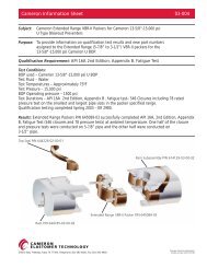
- Page 23 and 24: Kit Part NumbersBOP Size (in.) Pres
- Page 25 and 26: Tandem Boosters for U BOPsA BOP equ
- Page 27 and 28: UM BOPsThe Cameron UM BOP is a ligh
- Page 29 and 30: UM BOP Operating Data and Fluid Req
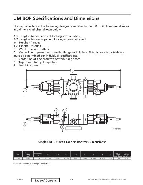
- Page 31: UM BOP Specifications and Dimension
- Page 35 and 36: 7-1/16” UM BOP Part NumbersItem N
- Page 37 and 38: 11” UM BOP Part NumbersItem No. D
- Page 39 and 40: 13-5/8” UM BOP Part NumbersItem N
- Page 41 and 42: Tandem Boosters for UM BOPsA BOP eq
- Page 43 and 44: U, UL and UM BOP Pipe RamsPipe rams
- Page 45 and 46: Part Numbers for U, UL & UM BOP Pip
- Page 47 and 48: Hang-Off WeightsHang-off weights ar
- Page 49 and 50: H 2 S Shearing Blind RamU, UL and U
- Page 51 and 52: ISR Shearing Blind RamInterlocking
- Page 53 and 54: U, UL and UM BOP Variable Bore Rams
- Page 55 and 56: Inserted PackersThe Cameron Inserte
- Page 57 and 58: Hydraulic Bonnet Bolt SystemThe hyd
- Page 59 and 60: Bonnet Seal Carriers for U, UM and
- Page 61 and 62: UIIBOPThe Cameron U II BOP takes al
- Page 63 and 64: U II BOP DimensionsThe following de
- Page 65 and 66: U II BOP Part NumbersItemNumberDesc
- Page 67 and 68: U II BOP Pipe RamsPipe rams are ava
- Page 69 and 70: U II BOP Shearing Blind RamsCameron
- Page 71 and 72: T BOPThe Cameron T blowout prevente
- Page 73 and 74: OPENPORTLOCKPORTCLOSEPORTRam Open;
- Page 75 and 76: 2006 Volvo S60Storing stations auto
- Page 78 and 79: 18-3/4” 15,000 psi WP T BOP Part
- Page 80 and 81: TC1001 80 © 2002 Cooper Cameron, C
- Page 82 and 83:
TL BOP Heights and WeightsBOPSize a
- Page 84 and 85:
Reference Page 86RAM Lock3 2 5 6 7
- Page 86 and 87:
39284439513935392534731645333031342
- Page 88 and 89:
39284439513935392534731645333031342
- Page 90 and 91:
15161317101215262521302954976181919
- Page 92 and 93:
151610191911171813315171215SD 03462
- Page 94 and 95:
1944 8 7 81534 35 363131927 458 7 8
- Page 96 and 97:
91031ST-Lock Assembly Components271
- Page 98 and 99:
484650 49 47“Lock” Port533940
- Page 100 and 101:
4640`A’413925`A’26Typ 8 Places2
- Page 102 and 103:
TL BOP Super Shear BonnetsA TL BOP
- Page 104 and 105:
T and TL BOP Pipe RamsPipe rams are
- Page 106 and 107:
T and TL BOP Pipe Ram Part Numbers
- Page 108 and 109:
T and TL BOP DVS Shear RamsDouble V
- Page 111 and 112:
C BOPThe Cameron C BOP was designed
- Page 113 and 114:
C BOP DimensionsBOP Size andWorking
- Page 115 and 116:
7-1/16” 10,000 psi WP C BOP Part
- Page 117 and 118:
13247Sequencing ValveSubassembly Co
- Page 119 and 120:
C BOP Shearing CapabilityMaterial S
- Page 121 and 122:
TC1001 121 © 2002 Cooper Cameron,
- Page 123 and 124:
S/QRC and G-2 BOP RamsBOPDescriptio
- Page 125 and 126:
D and DL Annular Blowout Preventers
- Page 127 and 128:
D and DL Annular BOP ComponentsItem
- Page 129 and 130:
7-1/16” 3000 - 20,000 psi WP D an
- Page 131 and 132:
11” 3000 - 10,000 psi WP D and DL
- Page 133 and 134:
13-5/8” 5000 - 16-3/4” 5000 psi
- Page 135 and 136:
18-3/4” 5000 - 21-1/4” 2000 psi
- Page 137 and 138:
DL Annular BOPReplacement Part Kits
- Page 139 and 140:
Clamp Connections (1-13/16” 10,00
- Page 141 and 142:
TC1001 141 © 2002 Cooper Cameron,