2002 Replacement Parts Catalog - cedip
2002 Replacement Parts Catalog - cedip
2002 Replacement Parts Catalog - cedip
- No tags were found...

You also want an ePaper? Increase the reach of your titles
YUMPU automatically turns print PDFs into web optimized ePapers that Google loves.
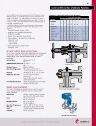
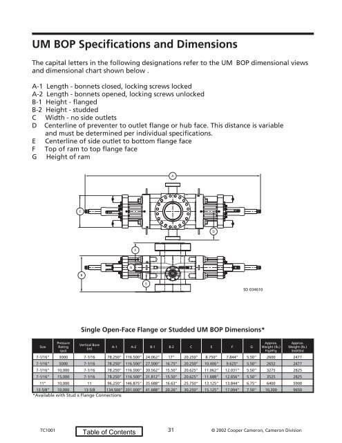
UM BOP Specifications and DimensionsThe capital letters in the following designations refer to the UM BOP dimensional viewsand dimensional chart shown below .A-1 Length - bonnets closed, locking screws lockedA-2 Length - bonnets opened, locking screws unlockedB-1 Height - flangedB-2 Height - studdedC Width - no side outletsD Centerline of preventer to outlet flange or hub face. This distance is variableand must be determined per individual specifications.E Centerline of side outlet to bottom flange faceF Top of ram to top flange faceG Height of ramACDFBGESD 034610Single Open-Face Flange or Studded UM BOP Dimensions*SizePressureRating(psi)Vertical Bore(in)A-1 A-2 B-1 B-2 C E F GApprox.Weight (lb.)FlgXFlgApprox.Weight (lb.)StdXStd7-1/16” 3000 7-1/16 78.250” 116.500” 24.062” 17” 20.250” 8.750” 7.844” 5.50” 2600 24777-1/16” 5000 7-1/16 78.250” 116.500” 27.500” 16.75” 20.250” 10.406” 9.625” 5.50” 2652 24777-1/16” 10,000 7-1/16 78.250” 116.500” 30.562” 15.50” 20.625” 11.062” 12.031” 5.50” 3275 28257-1/16” 15,000 7-1/16 78.250” 116.500” 31.812” 15.50” 20.625” 11.688” 12.656” 5.50” 3525 282511” 10,000 11 96.250” 146.875” 35.688” 16.63” 25.750” 13.125” 13.844” 6.75” 6400 590013-5/8” 10,000 13-5/8 134.500” 201.000” 41.688” 20.26” 30.250” 15.125” 17.094” 7.50” 10,300 9650*Available with Stud x Flange ConnectionsTC1001 31 © <strong>2002</strong> Cooper Cameron, Cameron Division