Mimaki Guide 2011.pdf - HOME
Mimaki Guide 2011.pdf - HOME
Mimaki Guide 2011.pdf - HOME

You also want an ePaper? Increase the reach of your titles
YUMPU automatically turns print PDFs into web optimized ePapers that Google loves.
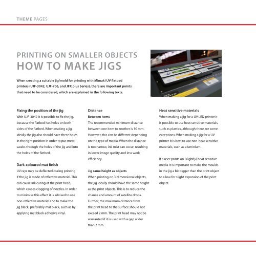
THEME PAGESTHEME PAGESPRINTING ON SMALLER OBJECTSHOW TO MAKE JIGSWhen creating a suitable jig/mold for printing with <strong>Mimaki</strong> UV flatbedprinters (UJF-3042, UJF-706, and JFX plus Series), there are important pointsthat need to be considered, which are explained in the following texts.Fixing the position of the jigWith UJF-3042 it is possible to fix the jig,because the flatbed has holes on bothsides of the flatbed. When making a jigideally the jig also should have these holesin the right position in order to put metalswabs through the holes of the jig and intothe holes of the flatbed.Dark-coloured mat finishUV rays may be deflected during printingif the jig is made of reflective material. Thiscan cause ink curing at the print head,which causes clogging of nozzles. In orderto minimise this effect it is advised to usenon-reflective material and to make thejig black, preferably mat black, such as byapplying mat black adhesive vinyl.DistanceBetween itemsThe recommended minimum distancebetween one item to another is 10 mm.However, this can be different dependingon the type of media. When the distanceis too narrow, ink mist can occur, resultingin lower image quality and less workefficiency.Jig same height as objectsWhen printing on 3-dimensional objects,the jig ideally should have the same heightas the print objects. This is to reduce thechance and amount of satellite drops.Further, the maximum distance fromthe print head to the surface should notexceed 2 mm. The print head may not bewarranted if it is used with a gap widerthan 2 mm.Heat sensitive materialsWhen making a jig for a UV LED printer itis possible to use heat sensitive materials,such as plastics, although there are someexceptions. When making a jig for a UVprinter it is best to use non-heat sensitivematerials, such as aluminium.If a user prints on (slightly) heat sensitivemedia it is important to make the mouldsin the jig a bit bigger than the print objectto allow for slight expansion of the printobject.UV LED VERSUS UV AND SOLVENTWith UJV-160 and JFX-1631, <strong>Mimaki</strong> is the first manufacturer that has implemented thepromising UV LED print technology in two large format printers. Below you can find thebenefits of UV LED print technology over other print technologies.IntroductionUV LED printing technology uses lightemitting diodes instead of metal halidelamps. It offers unique benefits overcompeting methods, such as conventionalUV and solvent inkjet printing.UV LED vs. Metal Halide LampOne of UV LED’s distinct advantages overconventional UV lamps is that LEDs createlittle or no heat. This is especially importantwhen it comes to printing on substratesthat are sensitive to deformation or colourchange due to overheating. In other words,users will be able to print on a wider varietyof substrates and applications.Furthermore, UV LED printing technologyenables faster operation and reduces costfor lamps and energy. Unlike metal halidelamps, LEDs do not require warm-up timeand they consume substantially less power.Also, UV LEDs last up to 5 times longer thanmetal halide lamps.UV LED vs. SolventWith UV LED technology, the ink is curedimmediately, eliminating drying time thatis required when using solvent ink. Theprint can be laminated directly (if needed).In addition, UV LED can print on more(uncoated) substrates than printing withsolvent ink.UV LEDMetal Halide LampLifetime (hours) About 10,000 hours About 1,000 hoursTemperature to media ±30 o ±80 oTurning on / off Instantly About 10 minutesType Name of Machine Power ConsumptionUV Metal Halide Lamp JF Series 4000 VA and belowSolvent Inkjet JV33 Series 1440 VA and belowUV LED UJF-3042 500 VA and below