KUKA Positioner - KUKA Robotics
KUKA Positioner - KUKA Robotics
KUKA Positioner - KUKA Robotics

Create successful ePaper yourself
Turn your PDF publications into a flip-book with our unique Google optimized e-Paper software.
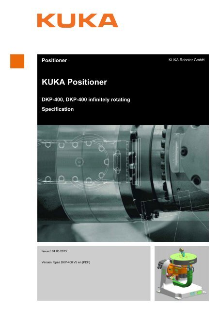
<strong>Positioner</strong><strong>KUKA</strong> Roboter GmbH<strong>KUKA</strong> <strong>Positioner</strong>DKP-400, DKP-400 infinitely rotatingSpecificationIssued: 04.03.2013Version: Spez DKP-400 V5 en (PDF)
<strong>KUKA</strong> <strong>Positioner</strong>© Copyright 2013<strong>KUKA</strong> Roboter GmbHZugspitzstraße 140D-86165 AugsburgGermanyThis documentation or excerpts therefrom may not be reproduced or disclosed to third parties withoutthe express permission of <strong>KUKA</strong> Roboter GmbH.Other functions not described in this documentation may be operable in the controller. The user hasno claims to these functions, however, in the case of a replacement or service work.We have checked the content of this documentation for conformity with the hardware and softwaredescribed. Nevertheless, discrepancies cannot be precluded, for which reason we are not able toguarantee total conformity. The information in this documentation is checked on a regular basis, however,and necessary corrections will be incorporated in the subsequent edition.Subject to technical alterations without an effect on the function.Translation of the original documentationKIM-PS5-DOCPublication:Pub Spez DKP-400 enBookstructure: Spez DKP-400 V4.1Version:Spez DKP-400 V5 en (PDF)2 / 51 Issued: 04.03.2013 Version: Spez DKP-400 V5 en (PDF)
<strong>KUKA</strong> <strong>Positioner</strong>7.1 Transportation ........................................................................................................... 398 <strong>KUKA</strong> Service ............................................................................................... 418.1 Requesting support ................................................................................................... 418.2 <strong>KUKA</strong> Customer Support ........................................................................................... 41Index ............................................................................................................. 494 / 51 Issued: 04.03.2013 Version: Spez DKP-400 V5 en (PDF)
1 Introduction1 Introduction1.1 Industrial robot documentationThe industrial robot documentation consists of the following parts:• Documentation for the manipulator• Documentation for the robot controller• Operating and programming instructions for the <strong>KUKA</strong> System Software• Documentation relating to options and accessories• Parts catalog on storage mediumEach of these sets of instructions is a separate document.1.2 Representation of warnings and notesSafetyThese warnings are relevant to safety and must be observed.are taken.These warnings mean that it is certain or highly probablethat death or severe injuries will occur, if no precautionsThese warnings mean that death or severe injuries mayoccur, if no precautions are taken.These warnings mean that minor injuries may occur, ifno precautions are taken.These warnings mean that damage to property may occur,if no precautions are taken.These warnings contain references to safety-relevant information orgeneral safety measures.These warnings do not refer to individual hazards or individual precautionarymeasures.This warning draws attention to procedures which serve to prevent or remedyemergencies or malfunctions:Procedures marked with this warning must be followedexactly.NotesThese hints serve to make your work easier or contain references to furtherinformation.Tip to make your work easier or reference to further information.1.3 Terms usedTermAxis rangeDrive unitDescriptionRange of an axis, in degrees, within which therobot/positioner may move. The axis range mustbe defined for each axis that is to be monitored.A combination of motor and gear unit.Issued: 04.03.2013 Version: Spez DKP-400 V5 en (PDF)5 / 51
<strong>KUKA</strong> <strong>Positioner</strong>TermWorkspaceBraking distanceCE mark(CE mark)EMTRelease deviceDanger zoneKCP<strong>KUKA</strong> positionerManipulatorRDCRobot systemSafety zoneFixtureExternal axisDescriptionThe robot/positioner is allowed to move within itsworkspace. The workspace is derived from theindividual axis ranges.The braking distance is the distance covered bythe robot/positioner after the stop function hasbeen triggered and before the robot comes to astandstill.The safety requirements of all relevant EC directiveshave been met. All prescribed conformityassessment procedures have been carried out.The EMT (electronic measuring tool) is used formastering the positioner with the KR C2.The release device can be used to move thepositioner mechanically after an accident or malfunction.The danger zone consists of the workspace andthe braking distances.The KCP (<strong>KUKA</strong> Control Panel) teach pendanthas all the operator control and display functionsrequired for operating and programming theindustrial robot.<strong>KUKA</strong> positioning system is a kinematic systemthat is controlled by the robot controller as anexternal axis. The shorter term “positioner” isused in the documentation.The robot arm and the associated electricalinstallationsThe RDC (Resolver Digital Converter) constitutesthe connection between the motors of therobot/positioner and the robot controller. The signalsare converted in the RDC (A/D conversion).Robot system, consisting of robot, positioner,robot controller, <strong>KUKA</strong> System Software, connectingcables and KCP.The safety zone is situated outside the dangerzone.A customer-specific fixture adapted to the relevantapplication is mounted on the positioner.If the positioner is connected to the robot controller,its axes are configured as external axes ofthe robot.6 / 51 Issued: 04.03.2013 Version: Spez DKP-400 V5 en (PDF)
2 Purpose2 Purpose2.1 Target groupThis documentation is aimed at users with the following knowledge and skills:• Advanced knowledge of mechanical engineering• Advanced knowledge of electrical and electronic systems• Advanced knowledge of programming external axes• Advanced knowledge of machine data• Knowledge of the robot controller systemFor optimal use of our products, we recommend that our customerstake part in a course of training at <strong>KUKA</strong> College. Information aboutthe training program can be found at www.kuka.com or can be obtaineddirectly from our subsidiaries.2.2 Intended useUseImpermissiblemisuseThe intended use of the positioner is the movement and positioning of loadsand workpieces.The positioner is designed exclusively for the specified applications.Use for any other or additional purpose is considered impermissible misuse.The manufacturer cannot be held liable for any damage resulting from suchuse. The risk lies entirely with the user.Operation in accordance with the intended use also involves continuous observanceof the operating instructions with particular reference to the maintenancespecifications.Any use or application deviating from the intended use is deemed to be impermissiblemisuse. This includes e.g.:• Transportation of persons and animals• Use as a climbing aid• Operation outside the permissible technical operating parameters• Use in potentially explosive environments• Underground operationChanging the structure of the positioner, e.g. by drillingholes, etc., can result in damage to the components. Thisis considered improper use and leads to loss of guarantee and liability entitlements.The positioner is an integral part of an overall system and may onlybe operated in a CE-compliant system.Issued: 04.03.2013 Version: Spez DKP-400 V5 en (PDF)7 / 51
<strong>KUKA</strong> <strong>Positioner</strong>8 / 51 Issued: 04.03.2013 Version: Spez DKP-400 V5 en (PDF)
3 Product description3 Product description3.1 OverviewThe DKP product family comprises the following positioner types:• DKP-400• DKP-400 infinitely rotatingThe positioners consist of the following components:• Base frame• Tilting axis• Rotational axisFig. 3-1: Components, example: DKP-4001 Rotational axis 3 Base frame2 Tilting axis3.2 Description of the positionerOverviewThe positioner has 2 axes, which are controlled via the robot controller. A customer-specificor project-specific fixture is mounted by means of a mechanicalinterface (e.g. locating holes and threaded holes). The system has an integratedenergy supply system (e.g. for compressed air, electrical current).In the following example, the tilting axis of the positioner is assigned to axis 7(A7) of the robot controller, while the rotational axis is assigned to axis 8 (A8).In the actual application, A7 and A8 might be assigned to different systemcomponents.Issued: 04.03.2013 Version: Spez DKP-400 V5 en (PDF)9 / 51
<strong>KUKA</strong> <strong>Positioner</strong>Fig. 3-2: Description, example: DKP-4001 Tilting axis motor 3 Rotational axis motor2 Swing frame 4 Base frameBase frameSwing frameThe base frame is the base of the positioner. It supports the tilting axis and isbolted to the floor.The swing frame is of cast design and serves as a mount for the motor and thegear unit of the rotational axis.Two stops on the swing frame and stop blocks fastened to the base frame limitthe range of the tilting axis. This provides the energy supply system and theface plate with mechanical protection against excessive tilting.Fig. 3-3: Tilting axis, mechanical limit stops1 Stop 4 Stop block2 Face plate 5 Stop block3 Energy supply systemBy default, moving the stop blocks allows gradual adjustment of the tiltingrange from +30°/+60°/+90° to -30°/-60°/-90°.10 / 51 Issued: 04.03.2013 Version: Spez DKP-400 V5 en (PDF)
3 Product descriptionSpecial stop blocks make it possible for all stops to be set from +0° to +90°and from -0° to -90°.AxesAccessoriesThe axes of the positioner each consist of a motor, gear unit and bearing.Only accessories authorized by <strong>KUKA</strong> Roboter GmbH for this positioner maybe used. All items of equipment must possess the appropriate certification anddeclarations of conformity.The positioner is fitted with an energy supply system. This energy supply systemcontains the following cables:DKP-400• Control cable• Ground cable, 70 mm 2• Air line 1/2"• PE ground conductorDKP-400 infinitely rotating• Ground cable, 70 mm 2The ground conductor, controlcable and air line are routed out ofthe turntable.The ground cable is fastened beneath the turntable to the current collector.Fig. 3-4: Energy supply system, DKP-400 and DKP-400 infinitely rotating1 Ground conductor, control cable and air line (only for DKP-400)2 Turntable3 Grounding cable4 Current collector5 DKP-4006 DKP-400 infinitely rotating3.3 Control and integrationDescriptionThe positioner is operated as an external axis of the robot controller. The followingcouplings are possible:• Asynchronous operation. There is no mathematical coupling with the robot.• Mathematical coupling into the robot kinematic system.An example of a mathematical coupling is depicted in the following diagram.Issued: 04.03.2013 Version: Spez DKP-400 V5 en (PDF)11 / 51
<strong>KUKA</strong> <strong>Positioner</strong>Fig. 3-5: Robot with external axes and extended kinematic systemWith mathematical coupling, the drive unit constantly follows the movement ofthe coupled external axes. The mathematical coupling can simplify the programmingfor complex processes, e.g. arc welding. Using this method, a constantdefined orientation can be maintained during a CP motion, for example.12 / 51 Issued: 04.03.2013 Version: Spez DKP-400 V5 en (PDF)
4 Technical data4 Technical data4.1 Basic dataBasic dataTypeDKP-400DKP-400 infinitely rotatingNumber of axes 2Pose repeatability ±0.1 mm(ISO 9283)WeightProtection classificationof the positionerSound levelDKP-400: approx. 300 kgDKP-400 infinitely rotating: approx. 300 kgIP 67< 70 dB (A) outside the working envelopeThe principal dynamic loads and the loads acting on the mounting base, dependon the project-specific design of the positioner and its attachments (energysupply system, mounting fixture, etc.). These must be calculated by thesystem user.Ambient temperatureOperation +5 °C to +40 °C (278 K to 313 K)Storage and transportation+5 °C to +40 °C (278 K to 313 K)Start-up +5 °C to +40 °C (278 K to 313 K)4.2 Axis dataAxis dataRange of motion, software-limitedDKP-400DKP-400 infinitely rotatingA7 -90° … +90° -90° … +90°A8 -190° … +190° infinitely rotatingThe axis speeds are shown in the following table.A7A894.5°/s126.0°/sSpeedsDirections ofrotationThe orientation of a rotational axis is defined as seen from the motor side:• “+” clockwise• “-” counterclockwiseIssued: 04.03.2013 Version: Spez DKP-400 V5 en (PDF)13 / 51
<strong>KUKA</strong> <strong>Positioner</strong>Fig. 4-1: Directions of rotation1 A7 (tilting axis) with positive and negative direction of rotation2 Cross hairs for calibrating an external kinematic system3 A8 (rotational axis) with positive and negative direction of rotationFurther information about calibrating external kinematic systems iscontained in the operating and programming instructions for the<strong>KUKA</strong> System Software (KSS).WorkingenvelopeThe working envelope must be defined by the customer, taking the projectspecificdimensions into consideration.4.3 PayloadsThe permissible payloads for the following DKP-400 positioners are specifiedin the following table:• DKP-400• DKP-400 infinitely rotatingPayloadsPayload400 kgMax. load torqueA7A8Load torque M LA7Tilting torque M KA7Load torque M LA8Tilting torque M KA81900 Nm7000 Nm750 Nm3550 NmMoment of inertia A8 64 kgm 214 / 51 Issued: 04.03.2013 Version: Spez DKP-400 V5 en (PDF)
4 Technical dataFig. 4-2: Permissible load values4.4 Plates and labelsPlates and labelsThe following plates, labels and signs are attached to the positioner. Theymust not be removed or rendered illegible. Illegible plates, labels and signsmust be replaced.The plates and labels in positions 1 and 4 are only attached to the DKP-400.Issued: 04.03.2013 Version: Spez DKP-400 V5 en (PDF)15 / 51
<strong>KUKA</strong> <strong>Positioner</strong>Fig. 4-3: Positions of plates and labels16 / 51 Issued: 04.03.2013 Version: Spez DKP-400 V5 en (PDF)
4 Technical dataFig. 4-4: Plates and labelsIssued: 04.03.2013 Version: Spez DKP-400 V5 en (PDF)17 / 51
<strong>KUKA</strong> <strong>Positioner</strong>18 / 51 Issued: 04.03.2013 Version: Spez DKP-400 V5 en (PDF)
5 Safety5 Safety5.1 General•This “Safety” chapter refers to a mechanical component of an industrialrobot.•If the mechanical component is used together with a <strong>KUKA</strong> robotcontroller, the “Safety” chapter of the operating instructions or assemblyinstructions of the robot controller must be used!This contains all the information provided in this “Safety” chapter. It alsocontains additional safety information relating to the robot controllerwhich must be observed.• Where this “Safety” chapter uses the term “industrial robot”, this also refersto the individual mechanical component if applicable.5.1.1 LiabilityThe device described in this document is either an industrial robot or a componentthereof.Components of the industrial robot:• Manipulator• Robot controller• Teach pendant• Connecting cables• External axes (optional)e.g. linear unit, turn-tilt table, positioner• Software• Options, accessoriesThe industrial robot is built using state-of-the-art technology and in accordancewith the recognized safety rules. Nevertheless, misuse of the industrialrobot may constitute a risk to life and limb or cause damage to the industrialrobot and to other material property.The industrial robot may only be used in perfect technical condition in accordancewith its designated use and only by safety-conscious persons who arefully aware of the risks involved in its operation. Use of the industrial robot issubject to compliance with this document and with the declaration of incorporationsupplied together with the industrial robot. Any functional disorders affectingsafety must be rectified immediately.Safety informationSafety information cannot be held against <strong>KUKA</strong> Roboter GmbH. Even if allsafety instructions are followed, this is not a guarantee that the industrial robotwill not cause personal injuries or material damage.No modifications may be carried out to the industrial robot without the authorizationof <strong>KUKA</strong> Roboter GmbH. Additional components (tools, software,etc.), not supplied by <strong>KUKA</strong> Roboter GmbH, may be integrated into the industrialrobot. The user is liable for any damage these components may cause tothe industrial robot or to other material property.In addition to the Safety chapter, this document contains further safety instructions.These must also be observed.Issued: 04.03.2013 Version: Spez DKP-400 V5 en (PDF)19 / 51
<strong>KUKA</strong> <strong>Positioner</strong>5.1.2 Intended use of the industrial robotThe industrial robot is intended exclusively for the use designated in the “Purpose”chapter of the operating instructions or assembly instructions.Further information is contained in the “Purpose” chapter of the operatinginstructions or assembly instructions of the industrial robot.Using the industrial robot for any other or additional purpose is considered impermissiblemisuse. The manufacturer cannot be held liable for any damageresulting from such use. The risk lies entirely with the user.Operating the industrial robot and its options within the limits of its intendeduse also involves observance of the operating and assembly instructions forthe individual components, with particular reference to the maintenance specifications.MisuseAny use or application deviating from the intended use is deemed to be impermissiblemisuse. This includes e.g.:• Transportation of persons and animals• Use as a climbing aid• Operation outside the permissible operating parameters• Use in potentially explosive environments• Operation without additional safeguards• Outdoor operation• Underground operation5.1.3 EC declaration of conformity and declaration of incorporationThis industrial robot constitutes partly completed machinery as defined by theEC Machinery Directive. The industrial robot may only be put into operation ifthe following preconditions are met:• The industrial robot is integrated into a complete system.Or: The industrial robot, together with other machinery, constitutes a completesystem.Or: All safety functions and safeguards required for operation in the completemachine as defined by the EC Machinery Directive have been addedto the industrial robot.• The complete system complies with the EC Machinery Directive. This hasbeen confirmed by means of an assessment of conformity.Declaration ofconformityDeclaration ofincorporationThe system integrator must issue a declaration of conformity for the completesystem in accordance with the Machinery Directive. The declaration of conformityforms the basis for the CE mark for the system. The industrial robot mustbe operated in accordance with the applicable national laws, regulations andstandards.The robot controller is CE certified under the EMC Directive and the Low VoltageDirective.The industrial robot as partly completed machinery is supplied with a declarationof incorporation in accordance with Annex II B of the EC Machinery Directive2006/42/EC. The assembly instructions and a list of essentialrequirements complied with in accordance with Annex I are integral parts ofthis declaration of incorporation.The declaration of incorporation declares that the start-up of the partly completedmachinery remains impermissible until the partly completed machinery20 / 51 Issued: 04.03.2013 Version: Spez DKP-400 V5 en (PDF)
5 Safetyhas been incorporated into machinery, or has been assembled with other partsto form machinery, and this machinery complies with the terms of the EC MachineryDirective, and the EC declaration of conformity is present in accordancewith Annex II A.The declaration of incorporation, together with its annexes, remains with thesystem integrator as an integral part of the technical documentation of thecomplete machinery.5.1.4 Terms usedTermAxis rangeStopping distanceWorkspaceOperator(User)Danger zoneService lifeKCP<strong>KUKA</strong> smartPADManipulatorSafety zoneStop category 0Stop category 1Stop category 2System integrator(plant integrator)T1T2External axisDescriptionRange of each axis, in degrees or millimeters, within which it may move.The axis range must be defined for each axis.Stopping distance = reaction distance + braking distanceThe stopping distance is part of the danger zone.The manipulator is allowed to move within its workspace. The workspaceis derived from the individual axis ranges.The user of the industrial robot can be the management, employer ordelegated person responsible for use of the industrial robot.The danger zone consists of the workspace and the stopping distances.The service life of a safety-relevant component begins at the time ofdelivery of the component to the customer.The service life is not affected by whether the component is used in arobot controller or elsewhere or not, as safety-relevant components arealso subject to ageing during storage.The KCP (<strong>KUKA</strong> Control Panel) teach pendant has all the operator controland display functions required for operating and programming theindustrial robot.The KCP variant for the KR C4 is called <strong>KUKA</strong> smartPAD. The generalterm “KCP”, however, is generally used in this documentation.See KCPThe robot arm and the associated electrical installationsThe safety zone is situated outside the danger zone.The drives are deactivated immediately and the brakes are applied. Themanipulator and any external axes (optional) perform path-orientedbraking.Note: This stop category is called STOP 0 in this document.The manipulator and any external axes (optional) perform path-maintainingbraking. The drives are deactivated after 1 s and the brakes areapplied.Note: This stop category is called STOP 1 in this document.The drives are not deactivated and the brakes are not applied. Themanipulator and any external axes (optional) are braked with a normalbraking ramp.Note: This stop category is called STOP 2 in this document.System integrators are people who safely integrate the industrial robotinto a complete system and commission it.Test mode, Manual Reduced Velocity ( 250 mm/s permissible)Motion axis which is not part of the manipulator but which is controlledusing the robot controller, e.g. <strong>KUKA</strong> linear unit, turn-tilt table, Posiflex.Issued: 04.03.2013 Version: Spez DKP-400 V5 en (PDF)21 / 51
<strong>KUKA</strong> <strong>Positioner</strong>5.2 PersonnelThe following persons or groups of persons are defined for the industrial robot:• User• PersonnelAll persons working with the industrial robot must have read and understoodthe industrial robot documentation, including the safetychapter.UserPersonnelThe user must observe the labor laws and regulations. This includes e.g.:• The user must comply with his monitoring obligations.• The user must carry out instructions at defined intervals.Personnel must be instructed, before any work is commenced, in the type ofwork involved and what exactly it entails as well as any hazards which may exist.Instruction must be carried out regularly. Instruction is also required afterparticular incidents or technical modifications.Personnel includes:• System integrator• Operators, subdivided into:• Start-up, maintenance and service personnel• Operating personnel• Cleaning personnelInstallation, exchange, adjustment, operation, maintenance and repairmust be performed only as specified in the operating or assemblyinstructions for the relevant component of the industrial robot and onlyby personnel specially trained for this purpose.System integratorOperatorExampleThe industrial robot is safely integrated into a complete system by the systemintegrator.The system integrator is responsible for the following tasks:• Installing the industrial robot• Connecting the industrial robot• Performing risk assessment• Implementing the required safety functions and safeguards• Issuing the declaration of conformity• Attaching the CE mark• Creating the operating instructions for the complete systemThe operator must meet the following preconditions:• The operator must be trained for the work to be carried out.• Work on the industrial robot must only be carried out by qualified personnel.These are people who, due to their specialist training, knowledge andexperience, and their familiarization with the relevant standards, are ableto assess the work to be carried out and detect any potential hazards.The tasks can be distributed as shown in the following table.22 / 51 Issued: 04.03.2013 Version: Spez DKP-400 V5 en (PDF)
5 SafetyTasks Operator ProgrammerSwitch robot controlleron/offSystem integratorx x xStart program x x xSelect program x x xSelect operating mode x x xCalibration(tool, base)Master the manipulator x xConfiguration x xProgramming x xStart-upMaintenanceRepairDecommissioningTransportationWork on the electrical and mechanical equipment of the industrial robotmay only be carried out by specially trained personnel.xxxxxxx5.3 Workspace, safety zone and danger zoneWorkspaces are to be restricted to the necessary minimum size. A workspacemust be safeguarded using appropriate safeguards.The safeguards (e.g. safety gate) must be situated inside the safety zone. Inthe case of a stop, the manipulator and external axes (optional) are brakedand come to a stop within the danger zone.The danger zone consists of the workspace and the stopping distances of themanipulator and external axes (optional). It must be safeguarded by means ofphysical safeguards to prevent danger to persons or the risk of material damage.Issued: 04.03.2013 Version: Spez DKP-400 V5 en (PDF)23 / 51
<strong>KUKA</strong> <strong>Positioner</strong>Fig. 5-1: Example of axis range A11 Workspace 3 Stopping distance2 Manipulator 4 Safety zone5.4 Overview of protective equipmentThe protective equipment of the mechanical component may include:• Mechanical end stops• Mechanical axis range limitation (optional)• Axis range monitoring (optional)• Release device (optional)• Labeling of danger areasNot all equipment is relevant for every mechanical component.5.4.1 Mechanical end stopsDepending on the robot variant, the axis ranges of the main and wrist axes ofthe manipulator are partially limited by mechanical end stops.Additional mechanical end stops can be installed on the external axes.If the manipulator or an external axis hits an obstructionor a mechanical end stop or axis range limitation, thiscan result in material damage to the industrial robot. The manipulator mustbe taken out of operation and <strong>KUKA</strong> Roboter GmbH must be consulted beforeit is put back into operation (>>> 8 "<strong>KUKA</strong> Service" Page 41).5.4.2 Mechanical axis range limitation (optional)Some manipulators can be fitted with mechanical axis range limitation in axesA1 to A3. The adjustable axis range limitation systems restrict the workingrange to the required minimum. This increases personal safety and protectionof the system.24 / 51 Issued: 04.03.2013 Version: Spez DKP-400 V5 en (PDF)
5 SafetyIn the case of manipulators that are not designed to be fitted with mechanicalaxis range limitation, the workspace must be laid out in such a way that thereis no danger to persons or material property, even in the absence of mechanicalaxis range limitation.If this is not possible, the workspace must be limited by means of photoelectricbarriers, photoelectric curtains or obstacles on the system side. There must beno shearing or crushing hazards at the loading and transfer areas.This option is not available for all robot models. Information on specificrobot models can be obtained from <strong>KUKA</strong> Roboter GmbH.5.4.3 Axis range monitoring (optional)Some manipulators can be fitted with dual-channel axis range monitoring systemsin main axes A1 to A3. The positioner axes may be fitted with additionalaxis range monitoring systems. The safety zone for an axis can be adjustedand monitored using an axis range monitoring system. This increases personalsafety and protection of the system.This option is not available for all robot models. Information on specificrobot models can be obtained from <strong>KUKA</strong> Roboter GmbH.5.4.4 Options for moving the manipulator without the robot controllerDescriptionThe following options are available for moving the manipulator after an accidentor malfunction:• Release device (optional)The release device can be used for the main axis drive motors and, dependingon the robot variant, also for the wrist axis drive motors.• Brake release device (option)The brake release device is designed for robot variants whose motors arenot freely accessible.• Moving the wrist axes directly by handIn the case of the low payload category, no release device for the wristaxes is available. A release device is not necessary, as the wrist axes canbe moved directly by hand.The options are only for use in exceptional circumstances and emergencies,e.g. for freeing people.Information on the availability of options for specific robot models canbe obtained from <strong>KUKA</strong> Roboter GmbH.The motors reach temperatures during operation whichcan cause burns to the skin. Contact must be avoided.Appropriate safety precautions must be taken, e.g. protective gloves must beworn.ProcedureMoving the manipulator with the release device:The following procedure must be followed exactly!1. Switch off the robot controller and secure it (e.g. with a padlock) to preventunauthorized persons from switching it on again.Issued: 04.03.2013 Version: Spez DKP-400 V5 en (PDF)25 / 51
<strong>KUKA</strong> <strong>Positioner</strong>2. Remove the protective cap from the motor.3. Push the release device onto the corresponding motor and move the axisin the desired direction.The directions are indicated with arrows on the motors. It is necessary toovercome the resistance of the mechanical motor brake and any otherloads acting on the axis.Moving an axis with the release device can damage themotor brake. This can result in personal injury and materialdamage. After using the release device, the motor must be exchanged.If a robot axis has been moved by the release device, allrobot axes must be remastered. Serious infuries or damageto property may otherwise result.ProcedureMoving the manipulator with the brake release device:Use of the brake release device may result in unexpectedrobot motions, especially sagging of the axes. Duringuse of the brake release device, attention must be paid to motion of this kindin order to be able to prevent physical injuries or damage to property. Standingunder moving axes is not permitted.The following procedure must be followed exactly!1. Switch off the robot controller and secure it (e.g. with a padlock) to preventunauthorized persons from switching it on again.2. Connect the brake release device to the base frame of the robot:Unplug connector X30 from interface A1. Plug connector X20 of the brakerelease device into interface A1.3. Select the brakes to be released (main axes, wrist axes) via the selectionswitch on the brake release device.4. Press the button on the hand-held device.The brakes of the main axes or wrist axes are released and the robot canbe moved manually.Further information about the brake release device can be found inthe documentation for the brake release device.5.4.5 Labeling on the industrial robotAll plates, labels, symbols and marks constitute safety-relevant parts of the industrialrobot. They must not be modified or removed.Labeling on the industrial robot consists of:• Identification plates• Warning labels• Safety symbols• Designation labels• Cable markings• Rating platesFurther information is contained in the technical data of the operatinginstructions or assembly instructions of the components of the industrialrobot.26 / 51 Issued: 04.03.2013 Version: Spez DKP-400 V5 en (PDF)
5 Safety5.5 Safety measures5.5.1 General safety measuresThe industrial robot may only be used in perfect technical condition in accordancewith its intended use and only by safety-conscious persons. Operatorerrors can result in personal injury and damage to property.It is important to be prepared for possible movements of the industrial roboteven after the robot controller has been switched off and locked. Incorrect installation(e.g. overload) or mechanical defects (e.g. brake defect) can causethe manipulator or external axes to sag. If work is to be carried out on aswitched-off industrial robot, the manipulator and external axes must first bemoved into a position in which they are unable to move on their own, whetherthe payload is mounted or not. If this is not possible, the manipulator and externalaxes must be secured by appropriate means.In the absence of operational safety functions and safeguards,the industrial robot can cause personal injury ormaterial damage. If safety functions or safeguards are dismantled or deactivated,the industrial robot may not be operated.Standing underneath the robot arm can cause death orserious injuries. For this reason, standing underneath therobot arm is prohibited!The motors reach temperatures during operation whichcan cause burns to the skin. Contact must be avoided.Appropriate safety precautions must be taken, e.g. protective gloves must beworn.KCPThe user must ensure that the industrial robot is only operated with the KCPby authorized persons.If more than one KCP is used in the overall system, it must be ensured thateach KCP is unambiguously assigned to the corresponding industrial robot.They must not be interchanged.The operator must ensure that decoupled KCPs are immediatelyremoved from the system and stored out ofsight and reach of personnel working on the industrial robot. This serves toprevent operational and non-operational EMERGENCY STOP devices frombecoming interchanged.Failure to observe this precaution may result in death, severe injuries or considerabledamage to property.Externalkeyboard,external mouseAn external keyboard and/or external mouse may only be used if the followingconditions are met:• Start-up or maintenance work is being carried out.• The drives are switched off.• There are no persons in the danger zone.The KCP must not be used as long as an external keyboard and/or externalmouse are connected.The external keyboard and/or external mouse must be removed as soon asthe start-up or maintenance work is completed or the KCP is connected.FaultsThe following tasks must be carried out in the case of faults in the industrialrobot:Issued: 04.03.2013 Version: Spez DKP-400 V5 en (PDF)27 / 51
<strong>KUKA</strong> <strong>Positioner</strong>• Switch off the robot controller and secure it (e.g. with a padlock) to preventunauthorized persons from switching it on again.• Indicate the fault by means of a label with a corresponding warning (tagout).• Keep a record of the faults.• Eliminate the fault and carry out a function test.ModificationsAfter modifications to the industrial robot, checks must be carried out to ensurethe required safety level. The valid national or regional work safety regulationsmust be observed for this check. The correct functioning of all safety circuitsmust also be tested.New or modified programs must always be tested first in Manual Reduced Velocitymode (T1).After modifications to the industrial robot, existing programs must always betested first in Manual Reduced Velocity mode (T1). This applies to all componentsof the industrial robot and includes modifications to the software andconfiguration settings.5.5.2 TransportationManipulatorRobot controllerExternal axis(optional)The prescribed transport position of the manipulator must be observed. Transportationmust be carried out in accordance with the operating instructions orassembly instructions of the robot.The prescribed transport position of the robot controller must be observed.Transportation must be carried out in accordance with the operating instructionsor assembly instructions of the robot controller.Avoid vibrations and impacts during transportation in order to prevent damageto the robot controller.The prescribed transport position of the external axis (e.g. <strong>KUKA</strong> linear unit,turn-tilt table, positioner) must be observed. Transportation must be carriedout in accordance with the operating instructions or assembly instructions ofthe external axis.5.5.3 Start-up and recommissioningBefore starting up systems and devices for the first time, a check must be carriedout to ensure that the systems and devices are complete and operational,that they can be operated safely and that any damage is detected.The valid national or regional work safety regulations must be observed for thischeck. The correct functioning of all safety circuits must also be tested.The passwords for logging onto the <strong>KUKA</strong> System Software as “Expert”and “Administrator” must be changed before start-up and mustonly be communicated to authorized personnel.The robot controller is preconfigured for the specific industrialrobot. If cables are interchanged, the manipulatorand the external axes (optional) may receive incorrect data and can thuscause personal injury or material damage. If a system consists of more thanone manipulator, always connect the connecting cables to the manipulatorsand their corresponding robot controllers.28 / 51 Issued: 04.03.2013 Version: Spez DKP-400 V5 en (PDF)
5 SafetyIf additional components (e.g. cables), which are not part of the scopeof supply of <strong>KUKA</strong> Roboter GmbH, are integrated into the industrialrobot, the user is responsible for ensuring that these components donot adversely affect or disable safety functions.If the internal cabinet temperature of the robot controllerdiffers greatly from the ambient temperature, condensationcan form, which may cause damage to the electrical components. Do notput the robot controller into operation until the internal temperature of thecabinet has adjusted to the ambient temperature.Function testMachine dataThe following tests must be carried out before start-up and recommissioning:It must be ensured that:• The industrial robot is correctly installed and fastened in accordance withthe specifications in the documentation.• There are no foreign bodies or loose parts on the industrial robot.• All required safety equipment is correctly installed and operational.• The power supply ratings of the industrial robot correspond to the localsupply voltage and mains type.• The ground conductor and the equipotential bonding cable are sufficientlyrated and correctly connected.• The connecting cables are correctly connected and the connectors arelocked.It must be ensured that the rating plate on the robot controller has the samemachine data as those entered in the declaration of incorporation. The machinedata on the rating plate of the manipulator and the external axes (optional)must be entered during start-up.The industrial robot must not be moved if incorrect machinedata are loaded. Death, severe injuries or considerabledamage to property may otherwise result. The correct machine datamust be loaded.5.5.4 Manual modeManual mode is the mode for setup work. Setup work is all the tasks that haveto be carried out on the industrial robot to enable automatic operation. Setupwork includes:• Jog mode• Teach• Programming• Program verificationThe following must be taken into consideration in manual mode:• If the drives are not required, they must be switched off to prevent the manipulatoror the external axes (optional) from being moved unintentionally.New or modified programs must always be tested first in Manual ReducedVelocity mode (T1).• The manipulator, tooling or external axes (optional) must never touch orproject beyond the safety fence.• Workpieces, tooling and other objects must not become jammed as a resultof the industrial robot motion, nor must they lead to short-circuits or beliable to fall off.Issued: 04.03.2013 Version: Spez DKP-400 V5 en (PDF)29 / 51
<strong>KUKA</strong> <strong>Positioner</strong>• All setup work must be carried out, where possible, from outside the safeguardedarea.If the setup work has to be carried out inside the safeguarded area, the followingmust be taken into consideration:In Manual Reduced Velocity mode (T1):• If it can be avoided, there must be no other persons inside the safeguardedarea.If it is necessary for there to be several persons inside the safeguarded area,the following must be observed:• Each person must have an enabling device.• All persons must have an unimpeded view of the industrial robot.• Eye-contact between all persons must be possible at all times.• The operator must be so positioned that he can see into the danger areaand get out of harm’s way.In Manual High Velocity mode (T2):• This mode may only be used if the application requires a test at a velocityhigher than Manual Reduced Velocity.• Teaching and programming are not permissible in this operating mode.• Before commencing the test, the operator must ensure that the enablingdevices are operational.• The operator must be positioned outside the danger zone.• There must be no other persons inside the safeguarded area. It is the responsibilityof the operator to ensure this.5.5.5 Automatic modeAutomatic mode is only permissible in compliance with the following safetymeasures:• All safety equipment and safeguards are present and operational.• There are no persons in the system.• The defined working procedures are adhered to.If the manipulator or an external axis (optional) comes to a standstill for no apparentreason, the danger zone must not be entered until an EMERGENCYSTOP has been triggered.5.5.6 Maintenance and repairAfter maintenance and repair work, checks must be carried out to ensure therequired safety level. The valid national or regional work safety regulationsmust be observed for this check. The correct functioning of all safety circuitsmust also be tested.The purpose of maintenance and repair work is to ensure that the system iskept operational or, in the event of a fault, to return the system to an operationalstate. Repair work includes troubleshooting in addition to the actual repairitself.The following safety measures must be carried out when working on the industrialrobot:• Carry out work outside the danger zone. If work inside the danger zone isnecessary, the user must define additional safety measures to ensure thesafe protection of personnel.30 / 51 Issued: 04.03.2013 Version: Spez DKP-400 V5 en (PDF)
5 Safety• Switch off the industrial robot and secure it (e.g. with a padlock) to preventit from being switched on again. If it is necessary to carry out work with therobot controller switched on, the user must define additional safety measuresto ensure the safe protection of personnel.• If it is necessary to carry out work with the robot controller switched on, thismay only be done in operating mode T1.• Label the system with a sign indicating that work is in progress. This signmust remain in place, even during temporary interruptions to the work.• The EMERGENCY STOP systems must remain active. If safety functionsor safeguards are deactivated during maintenance or repair work, theymust be reactivated immediately after the work is completed.Before work is commenced on live parts of the robot system,the main switch must be turned off and securedagainst being switched on again by unauthorized personnel. The incomingpower cable must be deenergized. The robot controller and mains supplylead must then be checked to ensure that it is deenergized.If the KR C4 or VKR C4 robot controller is used:It is not sufficient, before commencing work on live parts, to execute anEMERGENCY STOP or a safety stop, or to switch off the drives, as this doesnot disconnect the robot system from the mains power supply in the case ofthe drives of the new generation. Parts remain energized. Death or severeinjuries may result.Faulty components must be replaced using new components with the samearticle numbers or equivalent components approved by <strong>KUKA</strong> Roboter GmbHfor this purpose.Cleaning and preventive maintenance work is to be carried out in accordancewith the operating instructions.Robot controllerCounterbalancingsystemEven when the robot controller is switched off, parts connected to peripheraldevices may still carry voltage. The external power sources must therefore beswitched off if work is to be carried out on the robot controller.The ESD regulations must be adhered to when working on components in therobot controller.Voltages in excess of 50 V (up to 600 V) can be present in various componentsfor several minutes after the robot controller has been switched off! To preventlife-threatening injuries, no work may be carried out on the industrial robot inthis time.Water and dust must be prevented from entering the robot controller.Some robot variants are equipped with a hydropneumatic, spring or gas cylindercounterbalancing system.The hydropneumatic and gas cylinder counterbalancing systems are pressureequipment and, as such, are subject to obligatory equipment monitoring. Dependingon the robot variant, the counterbalancing systems correspond to category0, II or III, fluid group 2, of the Pressure Equipment Directive.The user must comply with the applicable national laws, regulations and standardspertaining to pressure equipment.Inspection intervals in Germany in accordance with Industrial Safety Order,Sections 14 and 15. Inspection by the user before commissioning at the installationsite.The following safety measures must be carried out when working on the counterbalancingsystem:• The manipulator assemblies supported by the counterbalancing systemsmust be secured.Issued: 04.03.2013 Version: Spez DKP-400 V5 en (PDF)31 / 51
<strong>KUKA</strong> <strong>Positioner</strong>• Work on the counterbalancing systems must only be carried out by qualifiedpersonnel.HazardoussubstancesThe following safety measures must be carried out when handling hazardoussubstances:• Avoid prolonged and repeated intensive contact with the skin.• Avoid breathing in oil spray or vapors.• Clean skin and apply skin cream.To ensure safe use of our products, we recommend that our customersregularly request up-to-date safety data sheets from the manufacturersof hazardous substances.5.5.7 Decommissioning, storage and disposalThe industrial robot must be decommissioned, stored and disposed of in accordancewith the applicable national laws, regulations and standards.5.6 Applied norms and regulationsName Definition Edition2006/42/EC Machinery Directive:Directive 2006/42/EC of the European Parliament and ofthe Council of 17 May 2006 on machinery, and amendingDirective 95/16/EC (recast)20062004/108/EC97/23/ECEN ISO 13850EN ISO 13849-1EN ISO 13849-2EN ISO 12100EN ISO 10218-1EMC Directive:Directive 2004/108/EC of the European Parliament and ofthe Council of 15 December 2004 on the approximation ofthe laws of the Member States relating to electromagneticcompatibility and repealing Directive 89/336/EECPressure Equipment Directive:Directive 97/23/EC of the European Parliament and of theCouncil of 29 May 1997 on the approximation of the lawsof the Member States concerning pressure equipment(Only applicable for robots with hydropneumatic counterbalancingsystem.)Safety of machinery:Emergency stop - Principles for designSafety of machinery:Safety-related parts of control systems - Part 1: Generalprinciples of designSafety of machinery:Safety-related parts of control systems - Part 2: ValidationSafety of machinery:General principles of design, risk assessment and riskreductionIndustrial robots:Safety200419972008200820082010201132 / 51 Issued: 04.03.2013 Version: Spez DKP-400 V5 en (PDF)
5 SafetyName Definition EditionEN 614-1EN 61000-6-2EN 61000-6-4EN 60204-1Safety of machinery:Ergonomic design principles - Part 1: Terms and generalprinciplesElectromagnetic compatibility (EMC):Part 6-2: Generic standards; Immunity for industrial environmentsElectromagnetic compatibility (EMC):Part 6-4: Generic standards; Emission standard for industrialenvironmentsSafety of machinery:Electrical equipment of machines - Part 1: Generalrequirements2006200520072006Issued: 04.03.2013 Version: Spez DKP-400 V5 en (PDF)33 / 51
<strong>KUKA</strong> <strong>Positioner</strong>34 / 51 Issued: 04.03.2013 Version: Spez DKP-400 V5 en (PDF)
6 Planning6 Planning6.1 Mounting baseThe mounting base is used to fasten the positioner to the floor.Grade of concretefor foundationsWhen producing foundations from concrete, observe the load-bearing capacityof the ground and the country-specific construction regulations. There mustbe no layers of insulation or screed between the bedplates and the concretefoundation. The quality of the concrete must meet the requirements of the followingstandard:• C20/25 according to DIN EN 206-1:2001/DIN 1045-2:2001To ensure that the anchor forces are safely transmitted to the foundation, observethe dimensions for concrete foundations specified in the following illustration.Fig. 6-1: Cross-section of foundations1 Base frame2 Grade of concrete in accordance with DIN 1045 B253 Minimum depth of concrete4 Min. distance to edge5 Concrete foundationHole patternIssued: 04.03.2013 Version: Spez DKP-400 V5 en (PDF)35 / 51
<strong>KUKA</strong> <strong>Positioner</strong>Fig. 6-2: Hole pattern for mounting base6.2 Face plate dimensionsThe face plate has the dimensions specified in the following diagram.36 / 51 Issued: 04.03.2013 Version: Spez DKP-400 V5 en (PDF)
6 PlanningFig. 6-3: Hole pattern for face plateIssued: 04.03.2013 Version: Spez DKP-400 V5 en (PDF)37 / 51
<strong>KUKA</strong> <strong>Positioner</strong>38 / 51 Issued: 04.03.2013 Version: Spez DKP-400 V5 en (PDF)
7 Transportation7 Transportation7.1 TransportationTransport dimensionsThe dimensions for the positioner can be noted from the following drawings.The specified dimensions refer to the positioner without equipment.Fig. 7-1: Transport dimensionsTransportpositionThe positioner may tip during transportation. Risk of personalinjury and damage to property. The positioner mustbe secured to prevent it from tipping.Fig. 7-2: Transport positionTransportationBefore the positioner is lifted, it must be ensured that it is free from obstructions.Remove all transport safeguards, such as nails and screws, in advance.First remove any rust or glue on contact surfaces.Use of unsuitable handling equipment may result in damageto the positioner. Only use handling equipment witha sufficient load-bearing capacity.Issued: 04.03.2013 Version: Spez DKP-400 V5 en (PDF)39 / 51
<strong>KUKA</strong> <strong>Positioner</strong>Fig. 7-3: <strong>Positioner</strong> with eyebolts1 Eyebolt1. Move positioner into its transport position.2. Provide two M16-ISO 3266 eyebolts with two 17-DIN7349 washers eachand screw them into two opposite M16 threads on the face plate.3. Fasten lifting tackle to the eyebolts.4. Lift the positioner using a crane or fork lift truck and transport it away.40 / 51 Issued: 04.03.2013 Version: Spez DKP-400 V5 en (PDF)
8 <strong>KUKA</strong> Service8 <strong>KUKA</strong> Service8.1 Requesting supportIntroductionInformationThe <strong>KUKA</strong> Roboter GmbH documentation offers information on operation andprovides assistance with troubleshooting. For further assistance, please contactyour local <strong>KUKA</strong> subsidiary.The following information is required for processing a support request:• Model and serial number of the robot• Model and serial number of the controller• Model and serial number of the linear unit (if applicable)• Model and serial number of the energy supply system (if applicable)• Version of the <strong>KUKA</strong> System Software• Optional software or modifications• Archive of the softwareFor <strong>KUKA</strong> System Software V8: instead of a conventional archive, generatethe special data package for fault analysis (via KrcDiag).• Application used• Any external axes used• Description of the problem, duration and frequency of the fault8.2 <strong>KUKA</strong> Customer SupportAvailability<strong>KUKA</strong> Customer Support is available in many countries. Please do not hesitateto contact us if you have any questions.ArgentinaRuben Costantini S.A. (Agency)Luis Angel Huergo 13 20Parque Industrial2400 San Francisco (CBA)ArgentinaTel. +54 3564 421033Fax +54 3564 428877ventas@costantini-sa.comAustraliaHeadland Machinery Pty. Ltd.Victoria (Head Office & Showroom)95 Highbury RoadBurwoodVictoria 31 25AustraliaTel. +61 3 9244-3500Fax +61 3 9244-3501vic@headland.com.auwww.headland.com.auIssued: 04.03.2013 Version: Spez DKP-400 V5 en (PDF)41 / 51
<strong>KUKA</strong> <strong>Positioner</strong>Belgium<strong>KUKA</strong> Automatisering + Robots N.V.Centrum Zuid 10313530 HouthalenBelgiumTel. +32 11 516160Fax +32 11 526794info@kuka.bewww.kuka.beBrazil<strong>KUKA</strong> Roboter do Brasil Ltda.Travessa Claudio Armando, nº 171Bloco 5 - Galpões 51/52Bairro AssunçãoCEP 09861-7630 São Bernardo do Campo - SPBrazilTel. +55 11 4942-8299Fax +55 11 2201-7883info@kuka-roboter.com.brwww.kuka-roboter.com.brChileRobotec S.A. (Agency)Santiago de ChileChileTel. +56 2 331-5951Fax +56 2 331-5952robotec@robotec.clwww.robotec.clChina<strong>KUKA</strong> <strong>Robotics</strong> China Co.,Ltd.Songjiang Industrial ZoneNo. 388 Minshen Road201612 ShanghaiChinaTel. +86 21 6787-1888Fax +86 21 6787-1803www.kuka-robotics.cnGermany<strong>KUKA</strong> Roboter GmbHZugspitzstr. 14086165 AugsburgGermanyTel. +49 821 797-4000Fax +49 821 797-1616info@kuka-roboter.dewww.kuka-roboter.de42 / 51 Issued: 04.03.2013 Version: Spez DKP-400 V5 en (PDF)
8 <strong>KUKA</strong> ServiceFrance<strong>KUKA</strong> Automatisme + Robotique SASTechvallée6, Avenue du Parc91140 Villebon S/YvetteFranceTel. +33 1 6931660-0Fax +33 1 6931660-1commercial@kuka.frwww.kuka.frIndia<strong>KUKA</strong> <strong>Robotics</strong> India Pvt. Ltd.Office Number-7, German Centre,Level 12, Building No. - 9BDLF Cyber City Phase III122 002 GurgaonHaryanaIndiaTel. +91 124 4635774Fax +91 124 4635773info@kuka.inwww.kuka.inItaly<strong>KUKA</strong> Roboter Italia S.p.A.Via Pavia 9/a - int.610098 Rivoli (TO)ItalyTel. +39 011 959-5013Fax +39 011 959-5141kuka@kuka.itwww.kuka.itJapan<strong>KUKA</strong> <strong>Robotics</strong> Japan K.K.YBP Technical Center134 Godo-cho, Hodogaya-kuYokohama, Kanagawa240 0005JapanTel. +81 45 744 7691Fax +81 45 744 7696info@kuka.co.jpCanada<strong>KUKA</strong> <strong>Robotics</strong> Canada Ltd.6710 Maritz Drive - Unit 4MississaugaL5W 0A1OntarioCanadaTel. +1 905 670-8600Fax +1 905 670-8604info@kukarobotics.comwww.kuka-robotics.com/canadaIssued: 04.03.2013 Version: Spez DKP-400 V5 en (PDF)43 / 51
<strong>KUKA</strong> <strong>Positioner</strong>Korea<strong>KUKA</strong> <strong>Robotics</strong> Korea Co. Ltd.RIT Center 306, Gyeonggi Technopark1271-11 Sa 3-dong, Sangnok-guAnsan City, Gyeonggi Do426-901KoreaTel. +82 31 501-1451Fax +82 31 501-1461info@kukakorea.comMalaysia<strong>KUKA</strong> Robot Automation Sdn BhdSouth East Asia Regional OfficeNo. 24, Jalan TPP 1/10Taman Industri Puchong47100 PuchongSelangorMalaysiaTel. +60 3 8061-0613 or -0614Fax +60 3 8061-7386info@kuka.com.myMexico<strong>KUKA</strong> de México S. de R.L. de C.V.Progreso #8Col. Centro Industrial Puente de VigasTlalnepantla de Baz54020 Estado de MéxicoMexicoTel. +52 55 5203-8407Fax +52 55 5203-8148info@kuka.com.mxwww.kuka-robotics.com/mexicoNorway<strong>KUKA</strong> Sveiseanlegg + RoboterSentrumsvegen 52867 HovNorwayTel. +47 61 18 91 30Fax +47 61 18 62 00info@kuka.noAustria<strong>KUKA</strong> Roboter Austria GmbHVertriebsbüro ÖsterreichRegensburger Strasse 9/14020 LinzAustriaTel. +43 732 784752Fax +43 732 793880office@kuka-roboter.atwww.kuka-roboter.at44 / 51 Issued: 04.03.2013 Version: Spez DKP-400 V5 en (PDF)
8 <strong>KUKA</strong> ServicePoland<strong>KUKA</strong> Roboter Austria GmbHSpółka z ograniczoną odpowiedzialnościąOddział w PolsceUl. Porcelanowa 1040-246 KatowicePolandTel. +48 327 30 32 13 or -14Fax +48 327 30 32 26ServicePL@kuka-roboter.dePortugal<strong>KUKA</strong> Sistemas de Automatización S.A.Rua do Alto da Guerra n° 50Armazém 042910 011 SetúbalPortugalTel. +351 265 729780Fax +351 265 729782kuka@mail.telepac.ptRussiaOOO <strong>KUKA</strong> <strong>Robotics</strong> RusWebnaja ul. 8A107143 MoskauRussiaTel. +7 495 781-31-20Fax +7 495 781-31-19kuka-robotics.ruSweden<strong>KUKA</strong> Svetsanläggningar + Robotar ABA. Odhners gata 15421 30 Västra FrölundaSwedenTel. +46 31 7266-200Fax +46 31 7266-201info@kuka.seSwitzerland<strong>KUKA</strong> Roboter Schweiz AGIndustriestr. 95432 NeuenhofSwitzerlandTel. +41 44 74490-90Fax +41 44 74490-91info@kuka-roboter.chwww.kuka-roboter.chIssued: 04.03.2013 Version: Spez DKP-400 V5 en (PDF)45 / 51
<strong>KUKA</strong> <strong>Positioner</strong>Spain<strong>KUKA</strong> Robots IBÉRICA, S.A.Pol. IndustrialTorrent de la PasteraCarrer del Bages s/n08800 Vilanova i la Geltrú (Barcelona)SpainTel. +34 93 8142-353Fax +34 93 8142-950Comercial@kuka-e.comwww.kuka-e.comSouth AfricaJendamark Automation LTD (Agency)76a York RoadNorth End6000 Port ElizabethSouth AfricaTel. +27 41 391 4700Fax +27 41 373 3869www.jendamark.co.zaTaiwan<strong>KUKA</strong> Robot Automation Taiwan Co., Ltd.No. 249 Pujong RoadJungli City, Taoyuan County 320Taiwan, R. O. C.Tel. +886 3 4331988Fax +886 3 4331948info@kuka.com.twwww.kuka.com.twThailand<strong>KUKA</strong> Robot Automation (M)SdnBhdThailand Officec/o Maccall System Co. Ltd.49/9-10 Soi Kingkaew 30 Kingkaew RoadTt. Rachatheva, A. BangpliSamutprakarn10540 ThailandTel. +66 2 7502737Fax +66 2 6612355atika@ji-net.comwww.kuka-roboter.deCzech Republic<strong>KUKA</strong> Roboter Austria GmbHOrganisation Tschechien und SlowakeiSezemická 2757/2193 00 PrahaHorní PočerniceCzech RepublicTel. +420 22 62 12 27 2Fax +420 22 62 12 27 0support@kuka.cz46 / 51 Issued: 04.03.2013 Version: Spez DKP-400 V5 en (PDF)
8 <strong>KUKA</strong> ServiceHungary<strong>KUKA</strong> <strong>Robotics</strong> Hungaria Kft.Fö út 1402335 TaksonyHungaryTel. +36 24 501609Fax +36 24 477031info@kuka-robotics.huUSA<strong>KUKA</strong> <strong>Robotics</strong> Corporation51870 Shelby ParkwayShelby Township48315-1787MichiganUSATel. +1 866 873-5852Fax +1 866 329-5852info@kukarobotics.comwww.kukarobotics.comUK<strong>KUKA</strong> Automation + <strong>Robotics</strong>Hereward RiseHalesowenB62 8ANUKTel. +44 121 585-0800Fax +44 121 585-0900sales@kuka.co.ukIssued: 04.03.2013 Version: Spez DKP-400 V5 en (PDF)47 / 51
<strong>KUKA</strong> <strong>Positioner</strong>48 / 51 Issued: 04.03.2013 Version: Spez DKP-400 V5 en (PDF)
IndexIndexNumbers2004/108/EC 322006/42/EC 3289/336/EEC 3295/16/EC 3297/23/EC 32AAccessories 11, 19Ambient temperature 13Applied norms and regulations 32Automatic mode 30Axes 11Axes, number 13Axis data 13Axis range 5, 21Axis range limitation 24Axis range monitoring 25BBase frame 10Basic data 13Brake defect 27Brake release device 25Braking distance 6, 21CCE mark 6, 20Center of gravity 39Cleaning work 31Components 9Connecting cables 19Counterbalancing system 31DDanger zone 6, 21Declaration of conformity 20Declaration of incorporation 19, 20Decommissioning 32Dimensions, transport 39Disposal 32Documentation, industrial robot 5Drive unit 5EEC declaration of conformity 20EMC Directive 20, 32EMT 6EN 60204-1 33EN 61000-6-2 33EN 61000-6-4 33EN 614-1 33EN ISO 10218-1 32EN ISO 12100 32EN ISO 13849-1 32EN ISO 13849-2 32EN ISO 13850 32Energy supply system 9External axes 6, 19, 21FFace plate 36Faults 27Function test 29GGeneral safety measures 27HHandling equipment 39Hazardous substances 32IIndustrial robot 19Intended use 20Introduction 5ISO 9283, repeatability 13KKCP 6, 21, 27Keyboard, external 27<strong>KUKA</strong> Customer Support 41<strong>KUKA</strong> smartPAD 21LLabeling 26Liability 19Linear unit 19Low Voltage Directive 20MMachine data 29Machinery Directive 20, 32Maintenance 30Manipulator 6, 19, 21, 24Manual mode 29Mechanical axis range limitation 24Mechanical end stops 24Motor 10Mounting base 35Mouse, external 27OOperator 21, 22Options 19Overload 27PPersonnel 22Plant integrator 21<strong>Positioner</strong> 6, 19Positioning system 6Pressure Equipment Directive 31, 32Preventive maintenance work 31Product description 9Protection classification, positioner 13Issued: 04.03.2013 Version: Spez DKP-400 V5 en (PDF)49 / 51
<strong>KUKA</strong> <strong>Positioner</strong>Protective equipment, overview 24Purpose 7RRange of motion 13RDC 6Reaction distance 21Recommissioning 28Release device 6, 25Repair 30Repeatability 13Robot controller 19Robot system 6Rotational axis 9Working envelope 14Working range limitation 24Workspace 6, 21, 23, 24SSafety 19Safety instructions 5Safety zone 6, 21, 23, 24Safety, general 19Service life 21Service, <strong>KUKA</strong> Roboter 41smartPAD 21Software 19Sound level 13Speeds 13Start-up 28STOP 0 21STOP 1 21STOP 2 21Stop category 0 21Stop category 1 21Stop category 2 21Stopping distance 21, 24Storage 32Support request 41Swing frame 10System integrator 20, 21, 22TT1 21T2 21Teach pendant 19Technical data 13Terms used 5Terms used, safety 21Terms, used 5Tilting axis 9Training 7Transportation 28, 39Turn-tilt table 19UUse, contrary to intended use 19Use, improper 19Use, intended 7User 21, 22WWarnings 5Weight 1350 / 51 Issued: 04.03.2013 Version: Spez DKP-400 V5 en (PDF)
<strong>KUKA</strong> <strong>Positioner</strong>Issued: 04.03.2013 Version: Spez DKP-400 V5 en (PDF)51 / 51