

View PDF - Painless Wiring
View PDF - Painless Wiring
View PDF - Painless Wiring

Create successful ePaper yourself
Turn your PDF publications into a flip-book with our unique Google optimized e-Paper software.
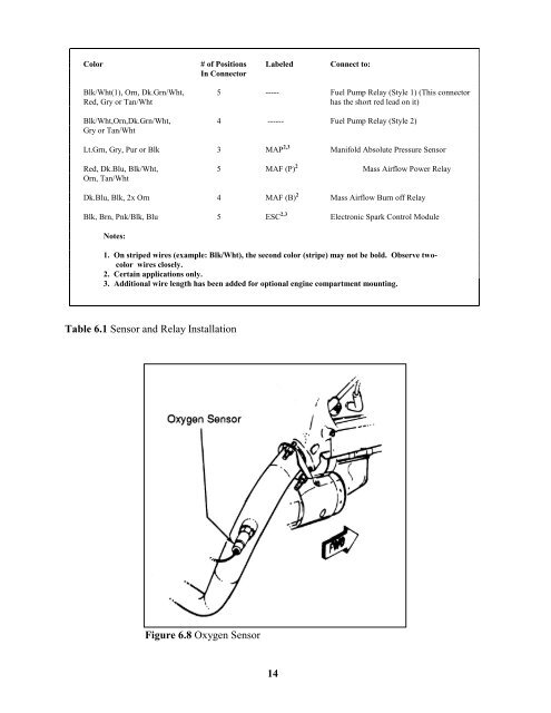
Color # of Positions Labeled Connect to:In ConnectorBlk/Wht(1), Orn, Dk.Grn/Wht, 5 ----- Fuel Pump Relay (Style 1) (This connectorRed, Gry or Tan/Whthas the short red lead on it)Blk/Wht,Orn,Dk.Grn/Wht, 4 ------ Fuel Pump Relay (Style 2)Gry or Tan/WhtLt.Grn, Gry, Pur or Blk 3 MAP 2,3 Manifold Absolute Pressure SensorRed, Dk.Blu, Blk/Wht, 5 MAF (P) 2 Mass Airflow Power RelayOrn, Tan/WhtDk.Blu, Blk, 2x Orn 4 MAF (B) 2 Mass Airflow Burn off RelayBlk, Brn, Pnk/Blk, Blu 5 ESC 2,3 Electronic Spark Control ModuleNotes:1. On striped wires (example: Blk/Wht), the second color (stripe) may not be bold. Observe twocolorwires closely.2. Certain applications only.3. Additional wire length has been added for optional engine compartment mounting.Table 6.1 Sensor and Relay InstallationFigure 6.8 Oxygen Sensor14


