View PDF - Painless Wiring
View PDF - Painless Wiring
View PDF - Painless Wiring
You also want an ePaper? Increase the reach of your titles
YUMPU automatically turns print PDFs into web optimized ePapers that Google loves.
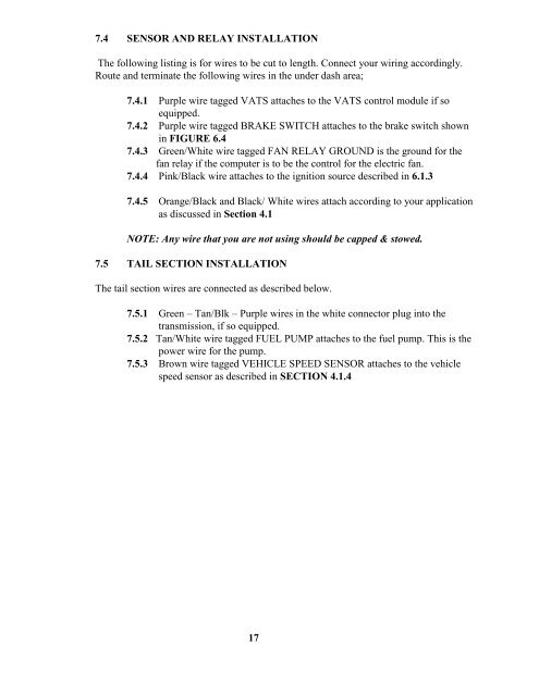
7.4 SENSOR AND RELAY INSTALLATIONThe following listing is for wires to be cut to length. Connect your wiring accordingly.Route and terminate the following wires in the under dash area;7.4.1 Purple wire tagged VATS attaches to the VATS control module if soequipped.7.4.2 Purple wire tagged BRAKE SWITCH attaches to the brake switch shownin FIGURE 6.47.4.3 Green/White wire tagged FAN RELAY GROUND is the ground for thefan relay if the computer is to be the control for the electric fan.7.4.4 Pink/Black wire attaches to the ignition source described in 6.1.37.4.5 Orange/Black and Black/ White wires attach according to your applicationas discussed in Section 4.1NOTE: Any wire that you are not using should be capped & stowed.7.5 TAIL SECTION INSTALLATIONThe tail section wires are connected as described below.7.5.1 Green – Tan/Blk – Purple wires in the white connector plug into thetransmission, if so equipped.7.5.2 Tan/White wire tagged FUEL PUMP attaches to the fuel pump. This is thepower wire for the pump.7.5.3 Brown wire tagged VEHICLE SPEED SENSOR attaches to the vehiclespeed sensor as described in SECTION 4.1.417


