View PDF - Painless Wiring
View PDF - Painless Wiring
View PDF - Painless Wiring
You also want an ePaper? Increase the reach of your titles
YUMPU automatically turns print PDFs into web optimized ePapers that Google loves.
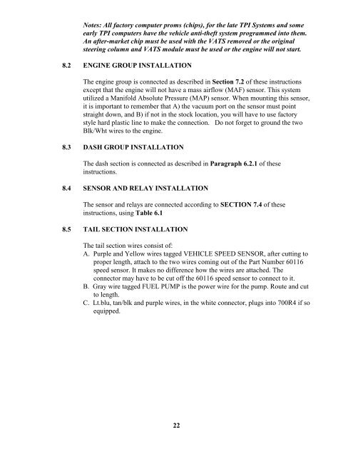
Notes: All factory computer proms (chips), for the late TPI Systems and someearly TPI computers have the vehicle anti-theft system programmed into them.An after-market chip must be used with the VATS removed or the originalsteering column and VATS module must be used or the engine will not start.8.2 ENGINE GROUP INSTALLATIONThe engine group is connected as described in Section 7.2 of these instructionsexcept that the engine will not have a mass airflow (MAF) sensor. This systemutilized a Manifold Absolute Pressure (MAP) sensor. When mounting this sensor,it is important to remember that A) the vacuum port on the sensor must pointstraight down, and B) if not in the stock location, you will have to use factorystyle hard plastic line to make the connection. Do not forget to ground the twoBlk/Wht wires to the engine.8.3 DASH GROUP INSTALLATIONThe dash section is connected as described in Paragraph 6.2.1 of theseinstructions.8.4 SENSOR AND RELAY INSTALLATIONThe sensor and relays are connected according to SECTION 7.4 of theseinstructions, using Table 6.18.5 TAIL SECTION INSTALLATIONThe tail section wires consist of:A. Purple and Yellow wires tagged VEHICLE SPEED SENSOR, after cutting toproper length, attach to the two wires coming out of the Part Number 60116speed sensor. It makes no difference how the wires are attached. Theconnector may have to be cut off the 60116 speed sensor to connect to it.B. Gray wire tagged FUEL PUMP is the power wire for the pump. Route and cutto length.C. Lt.blu, tan/blk and purple wires, in the white connector, plugs into 700R4 if soequipped.22


