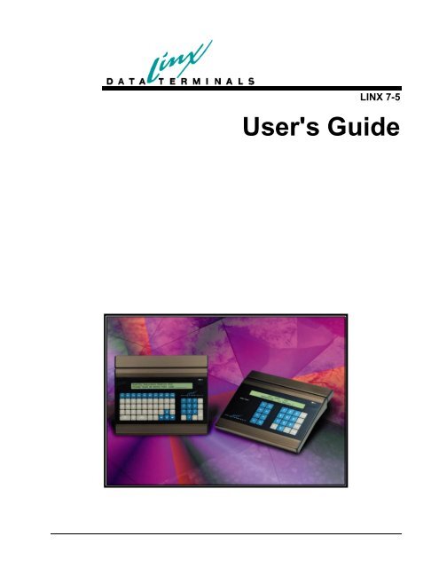
User's Guide - LINX Data Terminals
User's Guide - LINX Data Terminals
User's Guide - LINX Data Terminals
- No tags were found...

You also want an ePaper? Increase the reach of your titles
YUMPU automatically turns print PDFs into web optimized ePapers that Google loves.
March 12, 2007Copyright <strong>LINX</strong> <strong>Data</strong> <strong>Terminals</strong>, Inc.All Rights Reserved
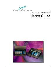
Overall DescriptionProduct PerspectiveThe Linx7-5 comprises of a new state-of-art motherboard installed in the current<strong>LINX</strong>5 chassis and using the current I/O board hardware. Consequently, the Linx7-5can be a cost effective alternative to buying completely new hardware to upgrade anetwork. It will be offered as a complete terminal and as an “upgrade kit” for current<strong>LINX</strong>5 users. It will interface to all existing I/O as well as add the capability for100mb Ethernet connectivity. It will be functionally similar to the current <strong>LINX</strong>5, soemployees should be not affected by the upgrade. Of course from a programming /configuration / maintenance standpoint, the Linx7-5 will be a different animalentirely from its predecessor. It will provide a more modern, non-proprietarydevelopment environment, “easy” configuration and management, and Ethernetconnectivity.Product FunctionsThe Linx7-5 will provide the functional equivalence of the current <strong>LINX</strong>5 and muchmore. For instance, it will provide for: a means of remote management anddiagnostics, standard TCP communications, and the capability to run an applicationin many different operating modes. These modes are explained in greater detailunder the “Using the <strong>LINX</strong> 7-5 <strong>Data</strong> Collection Terminal” Section.User CharacteristicsBecause the Linx7-5 is a functional equivalent of its predecessor, the user or operatorcharacteristics will remain unchanged.ConstraintsThe major design constraint for the first release of the Linx7-5 will be backwardcompatibility with the current <strong>LINX</strong>5 IO board and chassis.Requirements SubsetsFunctional Equivalence of Existing <strong>LINX</strong>5s• <strong>LINX</strong>5 I/O Board hardware/software connectivity• Magnetic Stripe Track 1 and 2 support (exclusive)• Standard Bar Code support• <strong>LINX</strong>5 Keyboard support (QWERTY and 24-Key only)• <strong>LINX</strong>5 Keyboard LED support• <strong>LINX</strong>5 LCD Display support (2x40 only)• Real Time Clock• Audio Alarm (with both frequency and duration)2 • Preface <strong>LINX</strong> 7-5 <strong>User's</strong> <strong>Guide</strong>
Using the Linx 7-5 <strong>Data</strong> Collection TerminalThe Linx 7-5 <strong>Data</strong> Collection Terminal is a programmable device, which gives it theability to adapt to a rather wide variety of uses. But since not all uses requiresophisticated (and complex) programming methods, Linx provides a variety of waysto control the DCT, ranging from complex methods that grant complete control butrequire considerable programming training, to much simpler methods that do notoffer as much functionality (although still quite a bit) but require little or no suchtraining.Linx provides a few small demo programs for all the methods that are discussed. Wecan also develop custom applications.From the Complex to the SimpleNative ModeThe most feature rich method of programming the Linx 7-5 DCT is what we call“native mode”. This is the most complex and expensive, but allows access to all ofthe terminal’s capabilities at high speed. There are comparatively few applications,such as high speed process control, where this mode will be required. The vastmajority of applications can comfortably use one of the simpler modes. Native modeis about what you might expect: it is essentially “C” programming using a crosscompilerto prepare programs that run directly under the control of the terminal’soperating system. In native mode, the terminal can operate autonomously, or it canoperate as a component in a network (including under the control of anothercomputer); the choice is up to you.The Linx7-5 can also support a single user defined task (application). Thisapplication must be created by the user or VAR, using a Motorola Coldfire ‘C’compiler. Currently, the Crossware Compiler is the only one supported. However,others will be validated in the future. <strong>LINX</strong> provides a "hook" for the user taskthrough ThreadX the real time operating system being utilized. Although <strong>LINX</strong> hasacquired source code and licenses for the stack, RTOS, and the compiler, the userand/or VAR will only require a user license for the compiler.<strong>LINX</strong> will provide a set of libraries for special I/O devices access.File access will occur through ‘C” API functions.TCP/IP stack socket function access will be included.Host Control ModeAlmost as feature rich as native mode is “HCL mode”. The major difference is thatthe controlling program runs on a host computer rather than on the terminal itself.Due to the delays that are associated with communications, this will almost alwayspreclude real-time applications, but otherwise grants a very high degree of controlover the terminal. The major drawback of Host Control Mode is that the terminal isnot autonomous; if the host becomes unavailable, the terminal becomes nonfunctional.Like Native mode, experience at programming should be consideredrequired.For the Windows host environment, Linx supplies several .NET based componentsthat allow rapid development of host applications. Sorry, no such tools currentlyexist for non-Windows environments, but we do supply the necessary reference4 • Preface <strong>LINX</strong> 7-5 <strong>User's</strong> <strong>Guide</strong>
materials. For an easier method of implementation, see the next mode: the LinxAutomator.Linx Automator ModeNote: Automator requires.NET 1.1 or higher.<strong>LINX</strong> Automator is a .NET class library intended to allow the development ofWindows based applications that can control one or more <strong>LINX</strong> VII-5 <strong>Data</strong>Collection <strong>Terminals</strong>. Although it bears a slight relationship to LinxScript, there isone huge difference: <strong>LINX</strong> Automator runs on a host, whereas LinxScript runs onthe terminal.<strong>LINX</strong> Automator is a companion to <strong>LINX</strong> HCL.NET, which is also a Windowsbased class library that can be used to control terminals. Either can be used todevelop host based terminal control applications, but they are significantly differentin underlying philosophy. HCL.NET can be thought of as the counterpart to “nativemode” programming on the terminals, whereas <strong>LINX</strong> Automator can be thought ofas the counterpart to LinxScript. HCL.NET grants more complete control of theterminal, but at the cost of greater complexity. Automator is simpler, but does notoffer the fine detail of control. For the majority of applications, we anticipate theAutomator will be the methodology of choice. Users needing to exercise the greaterdegree of control offered by HCL.NET should be prepared for a lengthier and morecomplex development cycle.Since Automator is a .NET class library, at least some knowledge of working with.NET is considered required. The user application can be written in either VB.NET,C#, or Managed C++. The demonstration application, a rather minimal one, iswritten in C#. It might be possible to develop applications in ASP.NET, but this wasnot a design criteria and no attempt to test the feasability of this approach has beenmade.Scripted ModeThis is the middle of the road; our own fairly simple programming language,LinxScript, that runs right on the terminal. LinxScript offers nearly complete controlof the terminal but without the complexities of either native or host controlledmodes.No particular type of host or other specialized tools are required; all you need is anFTP client and a text editor. Programming experience is helpful but not required;experienced programmers can usually start developing LinxScript almost right out ofthe box, and even non-programmers can usually develop and deploy modestapplications in a fairly short time.When using LinxScript, the terminal is typically autonomous; no host connection isrequired, although it is allowed. <strong>Data</strong> collected by the terminal can be retrievedeither via FTP, or via our “HostQueue” mechanism. The latter is our own protocolthat allows data to be collected from the terminal very quickly (usually almost realtime)while still allowing the terminal to operate (and data to be preserved) when thehost is not available. Linx supplies a Windows based application, “Evolution”, thatcan manage a network of such terminals. For the non-Windows environment, theappropriate reference material is available. HostQueue is a subset of the HostControl Mode mentioned earlier, but does not require a constant connection betweenthe host and the terminal.LinxScript does offer a limited ability for the application to perform arithmetic andto control “files” residing on the terminal. LinxScript also provides a limited abilityto operate in a cooperative manner with other computers. This ability is currentlyonly provided via the terminal’s serial ports, but Telnet capability is currently beingdeveloped and other mechanisms may be available in the future. LinxScript can also<strong>LINX</strong> 7-5 <strong>User's</strong> <strong>Guide</strong> Preface • 5
perform local validation of input; that is, the program can determine if the badge justswiped is valid (this does require that a list of valid badges be downloaded from thehost, which can be done via FTP).LinxScript is suitable for more complex Time & Attendance applications, and someeven more complex, that require some degree of local processing of the data (otherthan simple validation or formatting). Furthermore, LinxScript can also providetransaction based Terminal to host communications where the terminal sendsqueries and the Host responds accordingly. For instance, this can be used for Hostbasedlookups of employee information that is sent back to the terminal. Of course,any Host lookups must be done using a specially created Host application or byusing the Linx Evolution softwareSPIThe Simplified Programming Interface might be considered LinxScript, Junior. It isspecifically intended to be usable by non-programmers (although programmingexperience is useful) while still offering a fairly high degree of control. A SPI“program” is simply a set of rules, each of which describes what the terminal shoulddisplay at that time, and what sort of input it should accept from the user. Based onthat input, a new rule will be selected. When all the information that is desired hasbeen collected, it will be sent. SPI allows the same data delivery options thatLinxScript offers.Like LinxScript, SPI requires only the most basic of tools (a text editor and an FTPclient) to prepare and install programs. It also provides the local data validationability. Unlike LinxScript, SPI does not provide arithmetic, file control, or thelimited transactional ability.SPI is suitable for the majority of Time & Attendance applications, those that do notrequire local processing (other than formatting) of the collected data.ITAS“Integrated Time and Attendance” is the most basic mode. It does not require anyprogramming at all, being entirely table driven. ITAS “programs” can managesimple Time & Attendance applications, including local data validation, but offersvery few options regarding the number of displays that can be presented to the user.However, for the basic “Swipe & Go” or other such simple applications, an ITAS“program” can usually be prepared in just a few minutes even by non-programmers(this assumes a Windows based host). ITAS also offers both the FTP andHostQueue data delivery mechanisms available to the other modes.Linx provides a Windows based “Wizard” that can prepare ITAS configuration files.These files can also be edited via any suitable editor on non-Windows platforms.VT100 TELNET Terminal EmulationThis is (currently) the final mode of operation for the Linx 7-5 terminal. Since theVT100 Terminal Emulation mode is available to any Host that has a Telnet Server,this mode may be the easiest mode to implement, especially if you are already usingTerminal emulation. In this mode, the terminal acts and appears as a VT100Terminal. The operation and setup of this mode are detailed in Appendix G.6 • Preface <strong>LINX</strong> 7-5 <strong>User's</strong> <strong>Guide</strong>
Linx7-5 Terminal Hardware SynopsisThe Linx7-5 is an upgrade to the present <strong>LINX</strong>5 terminal and will provide10/100MB Ethernet connectivity. This upgrade terminal incorporates a TCP/IP stackand allows file downloads via FTP.The main hardware functions include:• Processor: Motorola Coldfire MCF5272 @ 66Mhz• Main Memory: 16MB SDRAM• Non-Volatile Memory: .5MB Battery-backed SRAM• Non-Volatile Program Storage: 2MB Flash• Real-time clock to provide non-volatile time and date information.• Serial interface to provide interoperability with the present <strong>LINX</strong>5 I/Oboard.• 3 OPTO-Isolated Digital input lines• 1 Relay control line• 3 TTL Digital output lines• A Mylar Speaker for audio tone generation.• 2 “Full” RS232 serial ports• 10/100MB Ethernet interface for high-speed network communication.<strong>LINX</strong> 7-5 <strong>User's</strong> <strong>Guide</strong> Preface • 7
Linx7-5 Block Diagram8 • Preface <strong>LINX</strong> 7-5 <strong>User's</strong> <strong>Guide</strong>
Powering the Linx7-5 terminalThe Linx7-5 has 4 major code blocks in flash memory. In order, these are:Boot block: This block contains most of the hardware low-levelinitialization code, boot diagnostics tests and the RS232 flash blockupdate code.Main block: This block contains more hardware initialization code and thehardware access functions.OS block: This is the largest and most important code block whichincludes the following:RTOS (Real Time Operating System)TCP/IP stack (including the Web server and the FTP server)Status displaysMenu systemAPI functions for the User ‘C’ applicationHCL executor responds to HCL commands from the Host in HCLapplication mode.<strong>LINX</strong> T&A Application task executes as defined in the configurationfile.Application block; This block contains the user ‘C’ application code ifthis operating mode is selected.If this message does notdisappear, the terminal isNOT functioning properly!When the terminal is first powered on the LCD display will show aninitialization string from the I/O board. If the I/O board powers onsuccessfully, the following message will be displayed for a very shorttime:8xC52 OK-V8.1 -displayed by <strong>LINX</strong> TerminalOnce, the I/O message disappears, the firmware in the Linx7-5 determines if the lowlevel'BOOT' diagnostics have been executed. If this is the very first power-on,(usually at the factory), or if the menu option: "Destructive SRAM Test" wasselected, the firmware will exercise a series of 'BOOT' diagnostics to ensure that thehardware is functional.These diagnostics include the following tests:• I/O Echo TestThis test will execute the "ECHO" command to the I/O board. The test willecho bytes 00,11,22,33...FF to verify that the I/O interface is operatingcorrectly.• RTC TestThis test will verify that the RTC can be accessed. RTC Address 55(hex)and 2A(hex) will be read/write verified with data patterns off 55(hex) andAA(hex). Minimal resources will be used. (Since the SDRAM has not beenverified yet!)<strong>LINX</strong> 7-5 <strong>User's</strong> <strong>Guide</strong> Preface • 9
• Synchronous DRAM TestsSDRAM Test #1;This test will destructively test the SDRAM. The following data patternswill be used to verify memory integrity:DATA: $55555555, $AAAAAAAA, $00000000SDRAM Test #2;This test will destructively test the SDRAM by initializing all uniqueaddresses with data to verify the integrity of the SDRAM address lines.• Battery-Backed SRAM TestsSRAM Test #1;This test will destructively test the SRAM. The following data patterns willbe used to verify memory integrity:DATA: $55555555, $AAAAAAAA, $00000000SRAM Test #2;This test will destructively test the SRAM by initializing all uniqueaddresses with data to verify the integrity of the SRAM address lines.• COM1 External Loopback TestThis test will detect if a “Loopback” plug has been installed. If it is found,then data 00-FF will be transmitted and then received to verify that UARTport #1 is operational.• COM2 External Loopback TestThis test will detect if a “Loopback” plug has been installed. If it is found,then data 00-FF will be transmitted and then received to verify that UARTport #2 is operational.• Ethernet Internal Loopback TestThis routine will verify that the Ethernet circuitry is operational. This willtest the Coldfire Ethernet MAC and the Level-One (Intel) 10/100mbPhysical Interface by executing an internal TX/RX loopback via the IntelLXT972A Physical Interface.• Keyboard LED testThis test will cycle through all of the keyboard LEDs. First turning all“ON”, then all “OFF”. Note: This test must be visually validated by theuser.• Keyboard ID TestThis test will prompt the user to “Press the Zero key”. This is used todetermine the type of keyboard installed on the terminal. This test will takeabout 3 seconds. Press and hold the “Zero” key repeatedly until a messageappears that indicates success or failure. If the detection process fails, thenthe terminal must be rebooted to try again. The terminal will NOT continueto boot until the keyboard type has been determined!NOTE: If any of these tests should fail, an error message will bedisplayed on the LCD to indicate failure mode.10 • Preface <strong>LINX</strong> 7-5 <strong>User's</strong> <strong>Guide</strong>
Once the 'BOOT' diagnostics have passed, the Linx7-5 will bootnormally.The Linx 7-5 Terminal Normal boot sequencePLEASE NOTE:The Ethernet cable MUSTbe plugged in beforepowering up the unit inorder for the TCP/IP stackto initialize properly.If the boot diagnostics have already been executed, the boot code willverify the integrity of the flash code blocks. A series of status messageswill be displayed for a brief time during these checks. The following isa brief description of these messages:1. A hardware version string will momentarily be shown.2. Main flash block validation will be indicated by the message:"Firmware Validation in Progress.." for 2 seconds.3. At this time, if a flash update is desired, press the "CLEAR" keyand the COM1 Upload utility will be started.(See Appendix B)- If the validation fails, the display will cycle the following error messages: (cycletime approx. 2 seconds)If these messages appear,the flash blocks MUST beloaded via the COM1 Portand the code will stay inthis message loop until adownload is started. (SeeAppendix B for moreinformation on flashupdating).WARNING: MAIN Code Checksum INVALID!Calculated checksum = xxxxxxxxand.NOTICE: MAIN CODE UPLOAD REQUIRED.Upload from COM1 Port: 9600 BaudAfter the boot code has determined that the flash blocks are valid. The normal bootsequence for the Linx7-5 consists of a series of status and information messages toinform the operator of the current configuration and/or status of the Linx7-5terminal. Following is the messages that are displayed:First Screen: Displayed for 1 secondLDT Linx7-5 - V1.0March 21 2004 10:31:21Line1: Terminal firmware VersionLine2: Firmware build date & timeSecond Screen: Displayed for 1 secondsssssssssssssss<strong>LINX</strong> 7-5 <strong>User's</strong> <strong>Guide</strong> Preface • 11
Line1: ssssssss=Terminal Serial NumberLine2: blankIf the terminal has not been configured, the following screen will be shown:Optional Third Screen: Displayed for 1 secondDefault Configuration SetEnter Parameters!Third Screen: Displayed for 2 secondsMarch 20,2002 10:31:22Line1: Date and Time string - centered -Line2: blankFourth Screen: Displayed for 2 secondsPress F1 to Enter SETUP menu…For detailed informationon this screen, refer to the"Linx7-5 Terminal StatusDisplay" section of thismanual.Fifth Screen: Displayed for 2 seconds (STATUS display!)tt:Waiting hh:mm wwwwK xxxxKOffline Q:qqqq L yyyyK zzzzKLine1 Miscellaneous configuration/status dataLine2 Miscellaneous configuration/status data12 • Preface <strong>LINX</strong> 7-5 <strong>User's</strong> <strong>Guide</strong>
The fifth (and final) screen shown will be dependent on the application modeselected in the “Terminal” menu. These options are:1. “HOST CMD Lang”This mode will display “Waiting for Host” until the HCL controlprogram is started on the Host. Once the Host has connected, thedisplay is under the control of the Host program.2. “User ‘C’ APP”In this mode, the display contents are completely controlled by the ‘C’executable.3. “Linx T&A PGM”In this mode, the display is also controlled by the T&A application.Note: The display prompts and messages are defined by the user via a“configuration utility”.4. “User Exe w/EVO”This mode operates as Mode #2, except that the HOST application isthe Linx Evolution Software.5. “VT100 Emulation”This mode provides a VT100 TELNET Client Terminal Emulation.For usage, see Appendix G.6. “Linx PGM #4”In this mode, the display will be controlled by the application. Thisapplication is TBD.PLEASE NOTE:The MENUS can ONLY be accessed when the “Press F1 to enter SETUP menu”screen is displayed and when the STATUS Display is available!<strong>LINX</strong> 7-5 <strong>User's</strong> <strong>Guide</strong> Preface • 13
Linx7-5 Terminal Status DisplaysThe Linx7-5 terminal has three status displays that are available to the user at any time. Thesedisplays are:1. Terminal Status Display - General Terminal Status2. Clock Status Display - Time and Date3. Configuration Status Display - Various configuration infoInvoking these status displays require special key combinations as follows:To invoke display:Terminal Status Display: Press ENTER and “OUT” keyClock Status Display:Press ENTER and “IN” keyConfiguration Status Display Press ENTER and “ZERO” keyDescriptions of these displays follow.Format for the Terminal Status displayAfter invocation, this status will be displayed for 5 seconds.The terminal status display has the following format:Waiting hh:mm wwwwK xxxxKOffline Q:qqqq L yyyyK zzzzKLine1 Terminal Connection stateLine1 hh:mm = hours:1/100 hrsLine1 wwwwK = Program space UsedLine1 xxxxK = Program space LeftLine2 Offline = Offline/online statusLine2 Q:qqqq = # queued Transmit packetsLine2 L = Link status indicator - 'L'= Link UP, no 'L'=Link DOWNLine2 yyyyK = File Space UsedLine2 zzzzK = File Space Left14 • Linx7-5 Terminal Status Displays <strong>LINX</strong> 7-5 <strong>User's</strong> <strong>Guide</strong>
Detailed Status Display FIELD DescriptionsLine #1 FIELD:'Waiting’ 'This field shows the current Host connection state of theLinx7-5 terminal.The following states are available:'Waiting''Ready''Connected'Host connecting process has notstartedHost connection has started andwaiting for the Host to connectThe Host has made a TCPconnection and data transfer canbegin.'hh''mm''wwww''xxxxThis field shows the current hour and will range from00-23.This field shows the current 1/100ths of an hour and willrange from 00-99.This field displays (in Kbytes) the current amount ofspace used by the User Application.This field displays (in Kbytes) the current amount ofspace remaining for the User Application.NOTE: The Cat5 cable must be installedbefore power up for the Ethernet driver toinitialize. (Or perform “RESET POWERUP”in diagnostics menu).Line #2 FIELD:'Offline''qqqq''L''yyyy'This is the current OFFLINE/ONLINE state of theLinx7-5 terminal. The Terminal is "ONLINE" only aftera TCP connection has been made. The possible statesare: 'Offline' and 'OnLine'.This field indicates the current number of User datapackets that are in the Transmit Queue ready to be sentto the Host. Currently, the maximum number of packetsthat can be queued is 2036.If displayed, indicates that the Ethernet link is Active. Ifnot displayed, a problem with the Ethernet cabling or theLinx7-5 terminal exists.Note: The 'link' must be present before the Linx7-5 cancommunicate over the LAN.This field displays (in Kbytes) the current amount ofspace used by the User File System.<strong>LINX</strong> 7-5 <strong>User's</strong> <strong>Guide</strong> Linx7-5 Terminal Status Displays • 15
'zzzz'This field displays (in Kbytes) the current amount ofspace remaining in the User File System.Configuration Status DisplayThis test will display the terminal configuration on the LCD display. This display is identicalto the display shown @ power-on. The following messages will be shown:• "LDT – Linx7-5"• "Version" "DATE" "TIME" (firmware build date/time)1 second pause• "Serial Number"1 second pause• • "Parameters Not Set!" (if configurationnot already set)• "Enter Parameters"1 second pause• "Status display line1"• "Status display line2"2 second pauseTime DisplayAfter invocation, this status will be displayed for 5 seconds.This test will display the current time and date. The display will auto-update when the timechanges at 1second intervals.16 • Linx7-5 Terminal Status Displays <strong>LINX</strong> 7-5 <strong>User's</strong> <strong>Guide</strong>
Linx7-5 Menu SystemOverview of Menu SystemThe <strong>LINX</strong> terminal has a local menu system to make configuration parametersaccessible and easy to change. They were designed to be: entered, changed andexited by pushing various keys on the keypad.There are 4 Main menus in the Linx7-5 terminal:1. "Terminal Menu" which is used to configure time, date, terminalidentification and passwords.2. "Network Menu" which is used to configure the TCP/IP parametersrequired for network communication.3. "Diagnostics Menu" which is used to test the various hardwaredevices on the Linx7-5.4. “Info Menu” which is used to display various information about thecurrent status of the Linx7-5 terminalUsing Menus from the KeypadSelecting a MenuIn order to access the menus, press the “F1” key when prompted by the display onpower-up.Any menu input field can be reset by pressing the "CLEAR" key at any time. If"ENTER" is pressed to save an entry, a BEEP may be heard if the entry isINVALID. In this case, the original parameter will not be changed. Also ‘EXIT” canbe pressed at any time and the option will not be changed.When “F1” is pressed, the display will change to:1-Terminal Menu< for next menuWhen the 'IN' is pressed, it will allow you to see the names of the three major menus,one at a time. Press 'IN'. The display changes to:2-Network Menu< for next menuPress 'IN' again:<strong>LINX</strong> 7-5 <strong>User's</strong> <strong>Guide</strong> Linx7-5 Menu System • 17
3-Diagnostics< for next menuPress 'IN' again:4-Info Menu< for next menuappears. Pressing 'IN' one more time will cause1-Terminal Menu< for next menuto reappear. Notice that if you skip past a menu, you can get back to it by pressing'IN' again, until the proper menu name appears. In addition to pressing 'IN', you canjust press the menu number to get it to appear. For example, if the Network Menu isshowing on the display, you can get to the Diagnostics Menu simply by pressing thenumber 3. The Diagnostics Menu will now appear on the display.Entering a Sub-menuWhen you have identified the menu you want to examine or modify, press ENTER.Examining & Selecting ParametersYou can scan through the list of parameters by pressing ENTER, and scanbackwards by pressing CLEAR. The parameter, which appears on the display, is theone, which is selected.For any password menuentry, pressing “CLEAR”,then ENTER will clear thepassword string!If a password has alreadybeen entered, the oldpassword must be enteredfirst! YOU HAVE 3 TRIESTO ENTER CORRECTLY!Changing ParametersOnce a parameter is selected, it may be changed. The settings oroptions suitable for that parameter can be examined/changed bypressing
Exiting Main MenuPressing EXIT from the Main Menu will exit the menus completely. The statusdisplay will appear, or in the case where a program has been already placed into theLinx7-5, whatever prompt the program defines.Diagnostics MenuLinx7-5 Menu DescriptionsOnce you have entered the diagnostics menu (by pressing ENTER from the 3-Diagnostics display, use “IN” and “OUT” to move through and select the diagnosticyou want to execute. Press ENTER to start the diagnostic. Pressing EXIT can stopmost diagnostics. Note: a test can be selected directly by pressing the test ID:0-9 andA-F.Terminal Menu1-Terminal Menu< for next MenuDEFAULTVALID MIN/MAXRANGE“Terminal Name” 0000000000 Max 16 Characters"Application Mode" HCL* CMD Lang (see text)"Time hhmmss" 000000 (0-23)(0-59)(0-59)"Date yymmddw" 040101 (02-29)(1-12)(1-31)"Menu Password" None 0-9999999"SupervisorPassword"None 0-9999999*HCL-“Host ControlLanguage”Terminal NameAllows defining a terminal name of up to 16 characters. This feature can helpmanage the Network but it is not required for normal operation. It can be used bythe Host/Server software to direct data to a specific <strong>LINX</strong>7-5 terminal.Application ModeThis selects the type of “user” application that will be executed by the terminal. Theoptions are:“HCL CMD Lang” (default) – Host controlled thin client“User ‘C’ APP” - User/VAR generated ‘C’ executable“Linx T&A PGM” - Table-drive Time and Attendance app.<strong>LINX</strong> 7-5 <strong>User's</strong> <strong>Guide</strong> Linx7-5 Menu System • 19
NOTE: “User ‘C’ APP w/EVO”should ONLY be selected if thehost software is using the <strong>LINX</strong>“Evolution” Service!“User ‘C’ APP w/EVO”“VT100 Telnet”“Linx PGM #4” -TBDTime hhmmssThis sets the time on the terminal. The entry must in the form: hh( hour 0-23)mm(minute 0-59) ss(second 0-59)Date yymmddwThis sets the date on the terminal. The entry must in the form: yy( year 02-29) mm(month 1-12) dd(day 1-31)optional: w(weekday 1-7). 1=SundayMenu Password0-9999999999When this is non-zero, the terminal user will be required to enter this value beforeaccess to the Configuration Menus is allowed. It is recommended to not give thisaccess code to anyone who does not need access to the terminal's menus.Supervisor PasswordIf the supervisor password has been initialized, it can be used as an alternatepassword for SETUP entry.Network Menu2-Network Menu< for next MenuDEFAULT VALID MIN/MAX RANGE"Remote TCP Port" 52440 5000-65535 (0xFFFF)“Network Speed” Auto-Negotiate (see text)“DHCP/BOOTP” Enabled Enabled/Disabled"Terminal IP Address" 192.168.0.1. 0.0.0.0 – 255.255.255.255"Gateway IP Address" 192.168.0.2 0.0.0.0 – 255.255.255.255"Sub-Network Mask" 255.255.255.0 0.0.0.0 – 255.255.255.255Remote TCP PortThis is the TCP port number that the HCL host application will use to "Connect".20 • Linx7-5 Menu System <strong>LINX</strong> 7-5 <strong>User's</strong> <strong>Guide</strong>
The terminal and the hostapplication must havematching subnet masks.Network SpeedThis is the network connection speed. Auto-Negotiate will auto detect and“negotiate” the recommended speed. However, if network hardware has problemswith this method, select a “fixed” speed.DHCP/BOOTPThis selects whether a “DHCP” server will be used to auto configure the networkparameters. IF DHCP/BOOTP is set, then the IP addresses and Subnet mask settingsare received from the server.IP Network AddressThis is 16-digit field that will accept TCP/IP Notation Addresses. In most cases yournetwork administrator has a system for selecting IP addresses for new computers(hosts). Have this person assign the number to you. This will be a set of 4 decimalvalues that are separated by periods. As an example:128.1.1.43The first 2 or three numbers (not digits) will usually be the same on EVERYcomputer in your company. You need to make sure that the IP address you assigndoes not conflict with any other computer on your network.You may be able to examine the \ETC\HOSTS file to get a list of all of the addressesin use at your company. If you are using a central Domain Name Server (a computerthat keeps track of all the IP addresses) then you will need to go to that machine toget a good list. Select an IP address for your <strong>LINX</strong> that starts with the same 3numbers and differs only in the last one.SETTING THE ADDRESS ON A <strong>LINX</strong> WITH NO DECIMAL POINTThe Linx7-5 may have a limited keyboard without a decimal point, so separate the numberswith the IN or OUT key. After entering the new address, press ENTER then EXIT to get outof the menus.SPECIAL NOTE FOR IP ADDRESSES:All IP address fields should be set to the configuration provided by a "Network SystemAdministrator".Arbitrary setting of these network parameters can create major network problems in theconnected LAN!The Terminal IP address is the IP address desired for the terminal, which shouldbe assigned by the IT system administrator. The terminal does not allowdynamically assigned IP addresses (DHCP/BootP)The Gateway IP address is the IP address of the local gateway, if one exists.The Sub-Network Mask is the required mask for the sub network sothat the terminal can receive data packets.Diagnostics Menu3-Diagnostics< for next Menu<strong>LINX</strong> 7-5 <strong>User's</strong> <strong>Guide</strong> Linx7-5 Menu System • 21
Although this test menu can be operated in the same fashion as the other menus,(ie: "IN" moves forward and "OUT" moves back), these tests can be accesseddirectly by pressing the corresponding prefix letter: "1" to "F". Thus pressing '6' willgo directly to the "LED Lamp Test". Pressing "ENTER" will execute the selectedtest and the "EXIT" key will halt the testing and return to the menu.(see Linx7-5 User Diagnostics chapter for more info)Information Menu4-Info Menu< for next MenuThis menu provides current information about the Linx7-5 terminal. Using the“Enter” key to scroll through the menu, the following information is displayed:Terminal Name:AccountingBoot Code Version: VERS 002 04/08/04Main Code Version: VERS 003 04/10/04OS Version:V1.00.00TCP Port: 52440Terminal IP Address: 192.168.0.122Gateway IP Address: 192.168.0.1Sub-Network Mask: 255.255.255.0Power-On Hours: 234Pressing ‘EXIT’ at any time will exit this menu.22 • Linx7-5 Menu System <strong>LINX</strong> 7-5 <strong>User's</strong> <strong>Guide</strong>
Linx7-5 User DiagnosticsKeypad/Barcode/MSR TestNOTE: If a proximityreader is connected and is“enabled”, this test willalso verify prox operation.This test will echo all keypad keys, barcode and magnetic swipe data to the LCD display.Display TestThis test will display all displayable characters on the LCD display.Destructive DRAM TestThis test will verify that the SDRAM memory can be tested with the following data patterns:DATA: 0x55555555, 0xAAAAAAAA, 0x00000000Destructive SRAM TestWARNING: Since theSRAM contains theterminal configurationparameters, a power cycleMUST be performed afterthis test:On Power-on, the “BootDiagnostics” will execute(as described in thePreface) and the terminalwill boot up normally butwith “default” parameters.Consequently, the userMUST enter Setup beforeusing the terminal.This test will verify that the SRAM memory can be tested with the following data patterns:DATA: 0x55555555, 0xAAAAAAAA, 0x00000000<strong>LINX</strong> 7-5 <strong>User's</strong> <strong>Guide</strong> Linx7-5 User Diagnostics • 23
Time DisplayLED Lamp TestThis test will display the current time and date. The display will auto-update when the timechanges at 1second intervals.This test will cycle all of the LED lamps in sequence. It is the user's responsibility to verifycorrect operation!COM Loopback TestCOM Transmit TestThis test will prompt the user for two parameters used by the test:Port(0,1) (0=COM1 1=COM2)BAUD (0-6) 0=1200 1=2400 2=4800 3=9600 4=19200 5=38400 6=57600On ‘ENTER” the test will start and display the results:“Testing Pass: xxxxxxxx Fail: xxxxxxxx”Pressing the ‘EXIT” key will stop the test.This test will prompt the user for two parameters used by the test:Port(0,1) (0=COM1 1=COM2)BAUD (0-6) 0=1200 1=2400 2=4800 3=9600 4=19200 5=38400 6=57600The test message is “The Quick Brown Fox Jumps Over the Lazy Dogs Back”.On ‘ENTER” the test will start and display the results:Line1: “Testing COMx Transmit at xxxxx BAUD”Line2: “TxPackets: xxxxxxxxPressing the ‘EXIT” key will stop the test.COM Receive TestThis test will prompt the user for two parameters used by the test:Port(0,1) (0=COM1 1=COM2)BAUD (0-6) 0=1200 1=2400 2=4800 3=9600 4=19200 5=38400 6=57600The test message is “The Quick Brown Fox Jumps Over the Lazy Dogs Back”.On ‘ENTER” the test will start and display the results:24 • Linx7-5 User Diagnostics <strong>LINX</strong> 7-5 <strong>User's</strong> <strong>Guide</strong>
Sense Lines TestPlease Note:Control Lines TestPlease Note:Line1: “Testing COMx Receive at xxxxx BAUD”Line2: “RxPkts: xxxxxxxx RxErrs: xxxxxxxxx“Pressing the ‘EXIT” key will stop the test.This test will verify that the Sense lines operate.This test MUST be performed with a special test board installed on J7(Digital I/O Connector).This test will verify that the Control lines operate.This test MUST be performed with a special test board installed on J7(Digital I/O Connector).Vsmart FIU TestSee “Post AssemblyVerification in Appendix‘F’ for more information.This test will verify that the Bioscript Vsmart Fingerprint Identification Unit isconfigured correctly and is operational. A test card with a fingerprint template isrequired for this test.Ethernet Internal LpbkEthernet Host Ping TestThis test will verify that the Ethernet can operate in internal loopback via the Level-One(Intel) PHY I/F.This routine will execute the ICMP ping command to the user requested Host IPaddress. This IP address must be entered when prompted by the test.Reset PowerUPThis test will reset the terminal similar to a power-on.Reset to DefaultsNote: All user settings willbe lost except for networkparameters!This routine will reset the terminal configuration to defaults. Then the terminal will bere-booted after configuration has been saved.<strong>LINX</strong> 7-5 <strong>User's</strong> <strong>Guide</strong> Linx7-5 User Diagnostics • 25
Linx7-5 Web ServerWeb Server OverviewThe Linx7-5 Web Server can be used to view terminal statistics, configure theterminal and perform simple maintenance tasks, such as rebooting the terminal. Theweb server is accessed via a web browser such as Internet Explorer or NetscapeCommunicator. The newer versions of the browsers must be used to provide all ofthe functionality of the web pages. IE5.0 and Netscape 6.0 (or later) have thecapabilities required.To view the main menu page execute the following:Assuming the Linx7-5 IP address = 15.126.45.23step #1: Open the browser of your choicestep #2: In the URL field, type "http://15.126.45.23" or "15.126.45.23"only - press The “Main Menu” page of the requested Linx7-5 terminal should have been loaded.26 • Linx7-5 Web Server <strong>LINX</strong> 7-5 <strong>User's</strong> <strong>Guide</strong>
Information and StatisticsThese links will display read-only information pages to the user.<strong>LINX</strong> 7-5 <strong>User's</strong> <strong>Guide</strong> Linx7-5 Web Server • 27
28 • Linx7-5 Web Server <strong>LINX</strong> 7-5 <strong>User's</strong> <strong>Guide</strong>
If the web server was usedto change the WEB login,then the configured “new”login MUST be used.Setup and ConfigurationThese links will display configuration pages that provide the user remote setupcapability. The pages allow the user to configure the terminal, network and barcodeparameters. The menu options are identical to the internal menu system of theterminal. However, the “Barcode” menu options are ONLY available via the webserver.A password entry box will be displayed. A valid user name and password MUST beentered before these pages will display!The default Login is:User:LinxWEBPassword:9729647090<strong>LINX</strong> 7-5 <strong>User's</strong> <strong>Guide</strong> Linx7-5 Web Server • 29
Secured “Terminal Setup” PageIf the “Application Mode”option is changed, theterminal will “Reboot” toinvoke the new mode.The terminal configuration options on this page are identical to the menu optionsdescribed in the “Linx7-5 Menu System” chapter, except for the “Configure DST”option. This link will provide another configuration page for Daylight Savings TimeControl.30 • Linx7-5 Web Server <strong>LINX</strong> 7-5 <strong>User's</strong> <strong>Guide</strong>
Secured “Daylight Savings Time Control” PageThe “date” and “timefields MUST also be filledto activate a re-sync,especially if the DSTparameters have beenmodified!The DST (Daylight Savings Time) configuration web page is used to Enable orDisable automatic DST time adjustments. The start and end times are completelyconfigurable via the entry fields. The start and end weeks denote the Sunday of theweek when the DST starts and terminates respectively. The options are 1-5, where“1” indicates the First week and “4” indicates the 4 th week. If “5” is used, the“LAST” week is selected. The last week may be the 4 th or 5 th dependent upon themonth.<strong>LINX</strong> 7-5 <strong>User's</strong> <strong>Guide</strong> Linx7-5 Web Server • 31
Secured “Network Setup” PageIf any Network option ischanged, the terminal will“Reboot” to invoke thenew settings.The Network configuration options on this page are identical to the menu optionsdescribed in the “Linx7-5 Menu System” chapter, except for the “Host InActivityTimeout “ option. This option configures the timeout before the terminal autodisconnects.The setting is 0-120 minutes. 0=No Timeout 120=2 hours.32 • Linx7-5 Web Server <strong>LINX</strong> 7-5 <strong>User's</strong> <strong>Guide</strong>
Secured “Barcode Setup” PageThis page allows the user to remotely configure the barcode decoder options. Theseconfiguration options are NOT available in the local menu system. Since Inputdevices have numerous settings, it was decided that it would be more efficient for theuser to configure via the web. As more input devices are added in future releases,these will be added to the web configuration pages.<strong>LINX</strong> 7-5 <strong>User's</strong> <strong>Guide</strong> Linx7-5 Web Server • 33
DEFAULTVALID MIN/MAX RANGE"Code 39 Enable" Enabled Enabled/Disabled“Industrial 2 of 5 Enable” Disabled Enabled/Disabled“Interleaved 2 of 5 Enable” Disabled Enabled/Disabled"UPC/EAN Enable" Disabled Enabled/UPC-EAN-JANEnable/UPC Only"Codabar Enable" Disabled Enabled/Disabled"Code 128 Enable" Disabled Enabled/Disabled“Code 39 Check Digits Disabled Enabled/DisabledEnable”“Code 39 ASCII Mode” Normal Normal/ASCII/Only Normal“I2 of 5 Check Digits Disabled Enabled/DisabledEnable”“I2 of 5 Minimum Length” 0 0/4-32 (0 = any length)“UPC Supplements” None None/2 Digit/5 Digit/2 and 5 Digit“Laser Retry Enable” Disabled Enabled/DisabledSecured “More Input Device Setup” Page34 • Linx7-5 Web Server <strong>LINX</strong> 7-5 <strong>User's</strong> <strong>Guide</strong>
If any Input Device optionis changed, the terminalwill “Reboot” to invoke thenew settings.If the web server was usedto change the WEB login,then the configured “new”login MUST be used.The input device configuration options on this page allow the use to Enable/Disablevarious additional input devices. The proximity reader options include:Enable/Disable and proximity reader compatibility. Also, the Bioscript Vsmartreader is enabled on this page.Maintenance and ControlThese links will provide simple maintenance tasks and password setup.A password entry box will be displayed. A valid user name and password MUST beentered before these pages will display!The default Login is:User:LinxWEBPassword:9729647090Secured “Terminal Control” Maintenance PageThe reset options requirethat the Linx7-5 be reset,thus the Web serverconnection will be closed.If one of these options isselected, please disconnectthe browser after clickingon the selection.Once the page has loaded, several counters can be reset; the terminalcan be rebooted or set to a "default configuration". Also, a status log isavailable for viewing.Moving the mouse over an option will display the description of thefunction in the text box under the buttons.<strong>LINX</strong> 7-5 <strong>User's</strong> <strong>Guide</strong> Linx7-5 Web Server • 35
Secured “Password Control” Maintenance PageIf spaces are required, usethe underscore (‘_’)character to separate workThe password control page allows the user to modify the login for the WEB and FTPservers. The “Secret Question” field is used to allow password recovery. Thequestion (max 39 characters) will be stored and used as a means of recovering thepasswords.Please note: Once the “defaults” have been changed, the new defineduser/password combination MUST be used to access either the WEB orFTP server.36 • Linx7-5 Web Server <strong>LINX</strong> 7-5 <strong>User's</strong> <strong>Guide</strong>
Secured “Password Recovery” Maintenance PageThe Password recovery page allows the user access to the defined user/passwordsusing the “Secret Question”. If the user enters the correct “Secret Answer”, thereturn page will display the currently configured WEB and FTP login information.<strong>LINX</strong> 7-5 <strong>User's</strong> <strong>Guide</strong> Linx7-5 Web Server • 37
Installing PeripheralsBack Plate connectorsCOM1/COM2 (DB9-M) ports are used to connect RS232 peripherals such as aserial printer, scale or a NULL modem cable from a PC. COM1 is also used as analternative method to update the flash program files.Com Port Connector Pins: (both identical)1 DCD (<strong>Data</strong> Carrier Detect)2 RXD ( Receive <strong>Data</strong>)3 TXD (Transmit <strong>Data</strong>)4 DTR (<strong>Data</strong> Terminal Ready)5 GND (Ground)6 DSR (<strong>Data</strong> Set Ready)7 RTS (Request to Send)8 CTS (Clear to Send)9 RI (Ring Indicator)Ethernet (RJ45) port is used to connect to the network with CAT-5 (or CAT-6)cable.38 • Installing Peripherals <strong>LINX</strong> 7-5 <strong>User's</strong> <strong>Guide</strong>
Power (3-pin Molex) port connects to the +5V-DC switching Power Supplyprovided with the Linx7-5 terminal.Power Connector Pins:1 +5 Volts2 Chassis/Earth Ground3 Signal GroundDue to PC tracelimitations, the relaycurrent must not exceed 0.5ampsDigital I/O (DB9-F) port is used to connect external switches, relays and any otherdevices that can be monitored via a sensor, or controlled via a control line. There are3 TTL control lines that provide 20ma for driving solid-state relays or similar. Onemore control line uses a relay that may switch power to a load directly. The relay israted: 0.5A @125VAC or 1A @24VDC (max VDC=60v).Digital I/O Connector Pins:1 Sensor Line # 1 Input2 Sensor Line #2 Input3 Sensor Line #3 Input4 Relay Wiper (Control line #4)5 Relay NO Output (Control Line #4) (NO=Normally open)6 TTL Control Line #1 Output7 TTL Control Line #2 Output8 TTL Control Line #3 Output9 Signal Ground<strong>LINX</strong> 7-5 <strong>User's</strong> <strong>Guide</strong> Installing Peripherals • 39
Wand/Laser (special DB9-M) port provides the connection for an “un-decoded”Bar Code laser scanner or a wand. The maximum scan rate for the current barcodedecoder is 40scans/sec. Thus the scanner must not exceed that rate. (The next releaseof the Linx7-5 hardware will incorporate a much more robust decode engine.)Wand/Laser Port Connector Pins:1 Laser SSY2 Wand/Laser <strong>Data</strong>3 Laser Read OK4 N.C. (no connect)5 Laser Trigger6 Laser Enable7 Signal Ground8 Signal Ground9 Power (+5 Volts)40 • Installing Peripherals <strong>LINX</strong> 7-5 <strong>User's</strong> <strong>Guide</strong>
AppendixesAppendix A10/100 Mb Ethernet Installation <strong>Guide</strong>linesThe RJ45 connector has 2 integral status LEDs that can help to diagnose networkproblems.The Green LED indicates Media Speed:On = l00 MBOff = 10 MBThe Orange LED indicates Link Status:On = Link is UpOff = Link is Down<strong>LINX</strong> 7-5 <strong>User's</strong> <strong>Guide</strong> Appendixes • 41
Appendix BFilename MUST be the name of the‘S19’ file FTP’d previously.Updating Code Blocks In FlashUpdating FLASH via Ethernet:The program and operating system components can be updated remotely using anEthernet connection. However, at this time, only the Host program can send thecommands necessary to update the flash memory containing the OS and program.Following are the steps the host must perform to update the program flash using theethernet:1. The host must start a FTP Client with the IP Address of the remoteLinx7-5. (ie: ftp 192.168.234.15 or equivalent)2. The host must issue the "user command" to get the login prompt with acorrect username/password combination.3. If the connection has been made, enter "binary" mode. This will set theFTP server to expect binary octets. (instead of ASCII).4. Send the desired 'S19' file to the Linx7-5 using the "put" command.5. If the file transferred correctly, "quit" the FTP connection.7. Now that the 'S19' file has been transferred to the Linx7-5 file system,the <strong>LINX</strong> Supplied OS Update Utility program must be used. Select the.S19 file from the directory and execute.8. The Host should immediately disconnect from the Linx7-5, since alloperating system processes will be halted. If the file is found by theOS, flash updating will commence and when completed, the terminalwill reboot.9. After approximately 10-15 seconds, the Host program should try to"ping" and ensure that the Linx7-5 is alive and well. If not, a localadministrator may have to intervene to determine why the terminal didnot respond.42 • Appendixes <strong>LINX</strong> 7-5 <strong>User's</strong> <strong>Guide</strong>
Updating FLASH via COM1 Port:The RS232 port can only be used for flash updates while in the boot code block. OnPower-Up, the message "Firmware Validation in Progress" signals a 2 second waitfor the "CLEAR" key to be pressed and held down. If pressed, the code will enter aRS232 upload program that will be indicated by the following message: "NOTICE:READY FOR FLASH CODE UPLOAD". Once, this message appears the"CLEAR" key may be released and the "S19" file upload can be started.To upload the S19 file, the RS232 port must be connected to a PC running a terminalemulation program such as "PROCOMM". The connection must be made using anormal serial cable and a RS232 NULL Modem converter. The converter must thenbe connected to the Linx7-5 COM1 RS232 port The COM port setting must be 9600BAUD, No Parity, 8 <strong>Data</strong> Bits and 1 STOP bit. (9600N81 PC default)Once the connection is complete, the terminal emulation program should send the"S19" file via an ASCII transfer. Once the transfer has completed, the upload codewill verify the S19 file. If the file passes an integrity check, the following messagewill appear: "File accepted. Flash programming started." then the desired flashblock will be programmed. The terminal will be rebooted and if the programmingwas successful, the terminal will boot into the normal startup code.<strong>LINX</strong> 7-5 <strong>User's</strong> <strong>Guide</strong> Appendixes • 43
Appendix CUsing FTP.EXE - Windows Command Line FTPClient with the Linx7-5The initial connection commands are as follows:Assume the Linx7-5 IP address is 56.23.145.23....step #1: type "ftp 56.23.145.23" the following messages should appear:"connected to 56.23.145.23""220 service ready""user :"step #1a: press "ftp>" should appearstep #2: type "user" the following message should appear:"Username"step #3: type AnOnYmOuS (NOTE: must be exact case!)(this is the only default user name)However, if the FTP login has been changed via the webserver, then the “new” user/password MUST be used!The following message should appear:"331 User name ok, need password""Password:"step #4: type AnOnYmOuS (NOTE: must be exact case!)(this is the only default password)However, if the FTP login has been changed via the webserver, then the “new” user/password MUST be used!If password was entered correctly, the following messageis displayed:"230 User logged in""ftp>"Now FTP commands can be entered. The most useful FTP commands for this FTPclient are listed in Table 1.step #5: To EXIT session - type "bye" (or "quit") 44 • Appendixes <strong>LINX</strong> 7-5 <strong>User's</strong> <strong>Guide</strong>
COMMON FTP OPERATIONSLIST Directory:To get a directory listing of the remote Linx7-5, type "ls". This will result in a list ofthe filenames in the current directory. Using "LS" will result in a verbose listing thatcan distinguish Linx7-5 stored files. Use “PWD” (Print Working Directory) toensure that you are located in the desired drive/directory.DOWNLOAD file to Linx7-5 default directory:To download a file to the Linx7-5, type "put" (or send) filename. This will load thefile and the session should respond with a message indicating that the operation wassuccessful. The file can be seen if "LS" is executed. The downloaded file will thefirst shown.Important Note:The “user” file area(DRIVE “D”) is only 250kin battery-backed SRAM.Since this area is limited insize, this area must ONLYbe used for files that arerequired by the userapplication such as the“.CFG” files.DOWNLOAD file to Linx7-5 user directory:Note: to download a file first type "cd" D:\ to change the workingdirectory to the SRAM disk. This will allow FTP to transfer the fileinto a "nonvolatile" file area. Next type "put filename" (ie:CLK.CFG)and the file will be loaded to the user file area. Typing "LS" will showthe file at the end of the directory listing as "\CLK.CFG".DELETE a file from Linx7-5 default directory:Any file loaded via FTP can be deleted from the remote directory using "delfilename". Executing "LS" will reveal that the file has been removed. Ensure thatyou are located in the correct drive!<strong>LINX</strong> 7-5 <strong>User's</strong> <strong>Guide</strong> Appendixes • 45
TABLE 1Most useful Windows FTP client utility (ftp.exe) commandlist! - shell to DOS prompt? - list commands – same as “help”ascii - set ASCII transfer mode (not valid in Linx 7-5)binary - Set BINARY transfer modebye - ends FTP sessiondelete - Remove file from current remote directorydir - List files in directory - short listingget - Retrieve a file from current remote directoryhelp - list commands - same as "?"lcd - Change Directory on local client - like "cd" in DOSls - List files in directory - short listingLS - List files in directory – long-verbose listingput - Send a file to the remote directorypwd - Print Working Directory - returns current directoryquit - Ends FTP sessionrecv - Retrieves a file from the remote directory - same as getsend - Send a file to the remote directory - same as putuser - Enter user name/password informationcd - Change working directory – NOTE: must be used to select Drivedesired. (ie: cd c:\temp – selects: drive c:\- directory temp)NOTE: Drive letter MUST always be used with this command!md - make directory - creates new directory in "current workingdirectory" (see cd above).rmdir - Removes directory from "current working directory"46 • Appendixes <strong>LINX</strong> 7-5 <strong>User's</strong> <strong>Guide</strong>
Appendix D<strong>LINX</strong> 7-5 MEMORY MAPF001FFFFF0010000CPU-internal I/O - 64KF00007FFF0000000CPU-internal Memory - 2K042000FF04200000 Real-Time-Clock - 256 bytes040000FF04000000 CPLD - 256 bytes0307FFFF03000000(256K Drive D: - Non-Volatile)Static RAM - 512K bytes02FFFFFF02000000(>8MB Drive C: - Volatile)16 MB Synchronous DRAM001FFFFF00180000 USER App code space - 512K bytes0017FFFF00080000 OS code 1.0 MB0007FFFF00020000 MAIN CODE - 384K0001FFFF0001C000Main Parameter Tables - 32 K0001BFFF00018000 Boot Parameter Tables - 32 K00017FFF00000000 BOOT CODE - 96 K<strong>LINX</strong> 7-5 <strong>User's</strong> <strong>Guide</strong> Appendixes • 47
Appendix EBefore setup,please read:Setup of the Bioscrypt V-Smart reader on theLinx7-5 TerminalThe Bioscrypt V-Smart FingerPrint reader is a device that can be connected toLinx7-5 terminals to provide "Biometric" security for any application that mayrequire it. The Bioscrypt V-Smart reader is a "double-validation" device that requiresa fingerprint template on a "MiFare" or "IClass" Smart Card and the correspondingmatching fingerprint placed on the sensor before validation is successful. Thisincreases security since "both" are always required. However, to allow the V-Smartto operate with the Linx7-5 terminal, the V-Smart and the terminal must be set upcorrectly."V-Prox/V-Flex/V-Pass/V-Smart/V-Station Operations Manual" and pay specialattention to: Appendixes A,D, and E!NOTE: You may have to removethe screw that holds the bottomcover. An Allen wrench has beenprovided for this purpose.NOTE: The PC RS232 setupis:57600 N 8 1(Please follow instructions inAppendix E)PLEASE NOTE:On the V-Smart Reader:1. Connect the supplied RS232 to RJ11 cable to the PC and the RJ11 jackon the bottom of the V-Smart reader. This is the "AUX" port and willbe used to pre-configure the V-Smart before attaching to the Linx7-5.2. Using the "Veri-Admin" software, set up the terminal as per theinstructions in the "Veri-Series: Setup <strong>Guide</strong>" document that is suppliedwith the V-Smart reader.3. Start the "Veri-Admin" software on the PC attached to the V-Smart.Execute "Network Setup" and configure the reader as described.4. After network has been set up, click on the reader ID in the networkconfiguration to enter the "Unit Parameters" dialog. All settings shouldstay at default - click on the "Communications" tab.5. Communications TAB setup:a. The HOST and AUX port MUST be left at 56700 BAUDb. Execute "Test Communications" to verify ports (use broadcastmode)c. Observe that the "Host Mode" is currently set to "0" This will bechanged before exiting the entire setup.d. Save "Unit Parameter" settings and enter "Smart Card SecuritySettings" dialog. A "SiteKey" should be created that matches theSiteKey that will stored on the smart card.Store this SiteKey in the V-Smart reader as instructed. This allows "ONLY" thesmart cards that have the correct SiteKey to be validated...This step is to be executed ONLY if the V-Smart reader (now in configuration) willbe connected directly to a Linx7-5 Terminal. For development and to providefingerprint enrollment, the "AUX" port can continueto be used. For Linx7-5development, connect the RS232 to RJ11 cable directly to one of the terminal COMports and the setup of the V-Smart reader is complete.48 • Appendixes <strong>LINX</strong> 7-5 <strong>User's</strong> <strong>Guide</strong>
NOTE:This mode is NOT secure! For deployment, the AUX port should be locked-down byattaching the supplied cover with the "Allen Head" screw provided.Linx7-5 communications should be via the RS485 port as stated in the nextparagraph.e. Once the SiteKey has been saved to the V-Smart, the reader must beconfigured to allow communications to the Linx7-5 terminal. Goback to the "Unit Parameters" "Communications" TAB andchange the "Host Mode" to Mode #2.This allows the RS485 to beactivated and the AUX port to be disconnected! Click the "Apply"button.After this has been executed, the PC will no longer be able to communicate without aRS485 to RS232 converter attached!!!!!!f. Lock the AUX port using the supplied cover and screw. This willeliminate re-configuration without the RS485 "Host" port issuing aspecial re-enable AUX port command.Note: This test will execute withthe FIU Reader configuration set to"Disabled" or "Enabled".On the Linx7-5 terminal:1. If the V-Smart reader has been re-configured to use the RS485 port forthe "Host", connect as per RS485 cabling instructions (see appendixF). Otherwise, the RS232 to RJ11 cable can be used. Connect thereader to either COM1 or COM2.2. Using a "Pre-enrolled" smart card, the "Reader to Terminal"communications can be verified using the "FIU Reader Test" (menuoption: 'C') in the Diagnostics menu of the terminal. Follow theinstructions and ensure that the reader is operational.3. "Enable" V-Smart via the password-protected "More Input Devices" webpage. This MUST be set to allow HCL, ITAS and 'C' user applicationsto use the V-Smart.<strong>LINX</strong> 7-5 <strong>User's</strong> <strong>Guide</strong> Appendixes • 49
APPENDIX FCabling requirements to use the V-Smart with theLinx7-5Parts required:1. Bioscrypt V-Smart MiFare reader w/15pin pigtail2. Linx supplied RS232 to RS485 converter board3. +12V power supply (V-Smart and Converter both req. +12v)4. +5V Linx 7-5 power supply5. Short RS232 DB9 female-female extension cable.Assembly Instructions:1. Find the following wires in the V-Smart Pigtail and strip ends:(if not already stripped!)a. blue/black wire: RS485(-)b. blue wire: RS485(+)c. black wire: Power GNDd. red wire: Power Input (+12v)e. green/yellow wire Earth GND2. Tie off all other wires - ensure none are shorting..Note: The following connections are to be made via the tinned leads onthe converter board using the crimp terminals provided with the V-Smart installation kit.Converter Board Tinned leads:Wire ColorSignal NameEGND Green Earth Ground+12 Red +12v DCGND Black 12v DC Common485+ Blue RS485+485- Blue/Black RS485-x------------------------------------x| x-R11-x || +--------------------+ || MH | X X X X X | MH | MH=Mounting Hole| +--------------------+ |+------------------------------------+EGND +12 GND 485+ 485-3. Connect pigtail blue/black wire (RS485-) and converter Blue/Black wiresusing a crimp terminal. (total: 2 wires)50 • Appendixes <strong>LINX</strong> 7-5 <strong>User's</strong> <strong>Guide</strong>
4. Connect pigtail blue wire (RS485+) and converter blue wire using acrimp terminal. (total: 2 wires)5. Connect pigtail black wire (Power GND) and 12v supply '-' black leadand converter black wire using a crimp terminal. (total: 3 wires)6. Connect pigtail red wire (Power Input) and 12v supply '+' white lead andconverter red wire using a crimp terminal. (total: 3 wires)7. Connect pigtail green/yellow wire (Earth GND) and the 12v supplyshrink-wrapped Earth GND lead and converter green wire using acrimp terminal. (total: 3 wires)8. If the V-SMart is ready for deployment, connect one end of the RS232extension cable to the desired COM port of the Linx7-5.Go to step #10If not already configured, then the V-Smart must be configured.These are the two possible connection methods for configuration via aRS232 COM port on the Configuration PC that has the Veri-Adminsoftware installed:If the V-Smart reader "Host Mode" has already been changed toMode #2, (HOST = RS485), the RS232 jack on the converter board can bedirectly cabled to a PC COM port.==>> Otherwise, if the "Host Mode" is still at "DEFAULT" Mode #0(HOST = AUX)), then the RS232 to RJ11 cable supplied with the V-Smartcan be used.(see Appendix E for configuration information).9. Connect the other end of the extension cable to the DB9 connector of theRS232-RS485 converter board.10. If available, connect the AC 'Y' adapter power cord to both powersupplies. Otherwise, there must be 2 AC power cords.11. If the Linx7-5 is ready for deployment, secure the Power Supplies toensure stability.(ie: use Velcro, double-sided tape, or tie-wraps)POST ASSEMBLY VERIFICATION:1. Power-On the terminal.2. Enter Setup by pressing the "F1" key as indicated on the display.3. Enter "Diagnostics" menu - press 'C' then "Enter" to enter the "FIUReader Test". Press '1' or '2' to select the COM port for testing andexecute the following instructions for verification of the installation.4. Using a pre-enrolled Smart Card:a. Hold the card in front of the V-Smart card reader (unit withoutfingerprint sensor). The V-Smart status LED should turn "Yellow".b. Place the enrolled finger on the sensor. Wait for a "Beep". If itreads, the LED will turn "Green" else it will turn "Red".c. If "Red" return to step "a".<strong>LINX</strong> 7-5 <strong>User's</strong> <strong>Guide</strong> Appendixes • 51
d. If "Green" the FIU diagnostic should display the ID and verificationpercentage.After ensuring the the V-Smart reader has been "Enabled" via the web interface, theLinx7-5 terminal security system is ready for use.52 • Appendixes <strong>LINX</strong> 7-5 <strong>User's</strong> <strong>Guide</strong>
Appendix GIMPORTANT NOTE:To effectively use theVT100 TerminalEmulation, a "QWERTY"keyboard should beinstalled on the Linx7-5!Using the VT100 Terminal Emulation on the Linx7-5The Linx7-5 terminal has a "built-in" VT100 emulation mode whichcan be enabled by changing the "Application Mode" in the "TerminalMenu" to "VT100 Telnet". The only extra operational requirement is aconfiguration file named: "TC.CFG" that MUST be loaded to theSRAM Non-Volatile drive (Drive D:) of the terminal via FTP. Linxsupplies a "Full" version of this file (sample follows) or it can becreated using a simple text editor.NOTE: The ONLY entry that MUST be present is the "SERVERIP=" line which indicates the server's IP address for the TELNET clientconnection. All others will default to allow a connection to a TELNETServer on Port #23.ie: SERVER IP=10.4.25.1 - A line feed is mandatory!VT100 Support:The Linx7-5 VT100 Terminal Emulation supports the following VT100/VT52functions:Note: ANSI Mode is the default on Power up.PF1-PF4 keysNormal and Application ModeNumeric Keypad KeysNormal and Application ModeCursor Key ModeUsing "ALT" with cursor key to generateVT100 codesSet VT52 ModeSet ANSI ModeChange to VT52 operationChange to ANSI operation (from VT52mode)ALL Cursor control escapesALL ERASE Line/Screen escapesTABs and TAB stopsCursor Position ReportStatus ReportTerminal RESETTerminal IdentifySet/Reset Modes:Line Feed ModeCursor Key ModeApplication Mode- Both ANSI/VT52 modes- Both ANSI/VT52 modes- ANSI only- ANSI only - Device Attibutes- ANSI only- VT52 only<strong>LINX</strong> 7-5 <strong>User's</strong> <strong>Guide</strong> Appendixes • 53
ANSI/VT52 ModeWraparound ModeKeyPad ModeSet/Reset VT100 LEDs - uses LEDs @ F7-F10Local and Remote ECHO of keys: determined by Server "ECHO" negotiationThe following keys can be defined in TC.CFG file:AYT ("Are You There") - default = F10AO ("Abort Output") - default = F8IP ("Interrupt Process") - defualt = F9The following keys are defined by the Linx7-5:ALT-EXIT = "ESC"ALT-LEFT = VT100 Left Arrow key codesALT-RIGHT = VT100 Right Arrow key codesALT-DOWN = VT100 Down Arrow key codesALT-UP = VT100 Up Arrow key codesF1-F4= VT100 PF1-PF4 keysSpecial Note:Using the "ALT" key (instead of a CTRL key) all of the ASCIICONTROL characters can be generated by the Linx7-5.(ie: ALT-H = "Backspace" equivalent to: ^H or CTRL-H)54 • Appendixes <strong>LINX</strong> 7-5 <strong>User's</strong> <strong>Guide</strong>
SAMPLE TC.CFG FILE (as supplied by <strong>LINX</strong>)NOTES:1. All lines that start with '#' or '[' are considered COMMENT lines2. All settings MUST be CAPITALIZED!3. Any setting not in the file will be set to zero or a standard default4. Setting must be defined immediately after the '=' character-no spaces[Telnet Client Config File][Server]# Set TELNET Server IP Address (ie: 10.45.234.2)SERVER IP=10.10.50.132# Set TELNET Server TCP Port (default = 23)TELNET PORT=1023[Control]# TELNET Logging to file "TC.LOG" (Non-Volatile Drive D:) { Yes = 1,No = 0 }# Note: Logging should normally NOT be enabled due to "security"issuesLOGGING=0# TELNET InActivity Timeout (in seconds) { 0 = NO timeout }INACTIVE TIMEOUT=0# Use RFIdeas Proximity Reader { Yes = 1, No = 0 }USE PROX=0# Use BiosCrypt (F)ingerprint (I)dentification (U)nit { Yes = 1, No =0 }USE FIU=0[Key mapping]#Note: F1-F4 provides VT100 PF1-PF4 function# Function Key # to provide (AO) "Abort Output" default=F8 {F:5-10}AO KEY=8<strong>LINX</strong> 7-5 <strong>User's</strong> <strong>Guide</strong> Appendixes • 55
# Function Key # to provide (IP) "Interrupt Process" default=F9 {F:5-10}IP KEY=9# Function Key # to provide (AYT) "Are You There" default=F10 {F:5-10}AYT KEY=1056 • Appendixes <strong>LINX</strong> 7-5 <strong>User's</strong> <strong>Guide</strong>
<strong>LINX</strong> 7-5 <strong>User's</strong> <strong>Guide</strong> Appendixes • 57