CNS STANDARD OPERATING PROCEDURE Two Photon ...
CNS STANDARD OPERATING PROCEDURE Two Photon ...
CNS STANDARD OPERATING PROCEDURE Two Photon ...

Create successful ePaper yourself
Turn your PDF publications into a flip-book with our unique Google optimized e-Paper software.
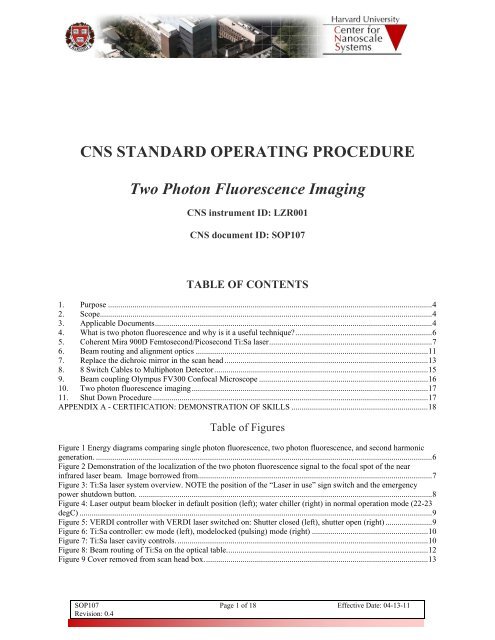
<strong>CNS</strong> <strong>STANDARD</strong> <strong>OPERATING</strong> <strong>PROCEDURE</strong><strong>Two</strong> <strong>Photon</strong> Fluorescence Imaging<strong>CNS</strong> instrument ID: LZR001<strong>CNS</strong> document ID: SOP107TABLE OF CONTENTS1. Purpose ............................................................................................................................................................... 42. Scope ................................................................................................................................................................... 43. Applicable Documents ........................................................................................................................................ 44. What is two photon fluorescence and why is it a useful technique? ................................................................... 65. Coherent Mira 900D Femtosecond/Picosecond Ti:Sa laser ................................................................................ 76. Beam routing and alignment optics .................................................................................................................. 117. Replace the dichroic mirror in the scan head .................................................................................................... 138. 8 Switch Cables to Multiphoton Detector ......................................................................................................... 159. Beam coupling Olympus FV300 Confocal Microscope ................................................................................... 1610. <strong>Two</strong> photon fluorescence imaging .................................................................................................................... 1711. Shut Down Procedure ....................................................................................................................................... 17APPENDIX A - CERTIFICATION: DEMONSTRATION OF SKILLS ................................................................... 18Table of FiguresFigure 1 Energy diagrams comparing single photon fluorescence, two photon fluorescence, and second harmonicgeneration. ..................................................................................................................................................................... 6Figure 2 Demonstration of the localization of the two photon fluorescence signal to the focal spot of the nearinfrared laser beam. Image borrowed from................................................................................................................... 7Figure 3: Ti:Sa laser system overview. NOTE the position of the “Laser in use” sign switch and the emergencypower shutdown button. ................................................................................................................................................ 8Figure 4: Laser output beam blocker in default position (left); water chiller (right) in normal operation mode (22-23degC) ............................................................................................................................................................................. 9Figure 5: VERDI controller with VERDI laser switched on: Shutter closed (left), shutter open (right) ....................... 9Figure 6: Ti:Sa controller: cw mode (left), modelocked (pulsing) mode (right) ......................................................... 10Figure 7: Ti:Sa laser cavity controls. ........................................................................................................................... 10Figure 8: Beam routing of Ti:Sa on the optical table. .................................................................................................. 12Figure 9 Cover removed from scan head box. ............................................................................................................. 13SOP107Revision: 0.4Page 1 of 18 Effective Date: 04-13-11
<strong>CNS</strong> <strong>STANDARD</strong> <strong>OPERATING</strong> <strong>PROCEDURE</strong>LZR001, <strong>Two</strong> <strong>Photon</strong> Fluorescence Imaging SystemFigure 10 Inside the scan head box. The dichroic mirror that separates the excitation beam from the signal beam ison the right. .................................................................................................................................................................. 14Figure 11. Gently insert Allen wrench into hole on right side of scan head to loosen the screw that holds the dichroicmirror in place. ............................................................................................................................................................ 14Figure 12 Dichroic mirror for the two photon fluorescence which is kept on the shelf in the rack of optics. Thevisible dichroic filter should be stored in a protective plastic box on this shelf when it is not in use. ........................ 15Figure 14 Changing PMT connector connections ....................................................................................................... 16SOP107Revision: 0.4Page 2 of 18 Effective Date: 04-13-2011
<strong>CNS</strong> <strong>STANDARD</strong> <strong>OPERATING</strong> <strong>PROCEDURE</strong>LZR001, <strong>Two</strong> <strong>Photon</strong> Fluorescence Imaging SystemCHANGE LOGRevision Date Author Changes0.1 02/23/2011 A McClelland Initial draft for two photon fluorescence SOP; portionstaken from Multiphoton SOP030.0.2 03/11/2011 E. Martin Formatting. Assigned #107.0.3 03/14/2011 A McClelland Updated Fig 90.4 04/13/2011 A McClelland Changed which spectrometer to use to measurewavelength. Changed which PMT detector to useSOP107Revision: 0.4Page 3 of 18 Effective Date: 04-13-2011
<strong>CNS</strong> <strong>STANDARD</strong> <strong>OPERATING</strong> <strong>PROCEDURE</strong>LZR001, <strong>Two</strong> <strong>Photon</strong> Fluorescence Imaging System1. Purpose2. Scope1.1. This document specifies the work instructions for the <strong>CNS</strong> <strong>Two</strong> <strong>Photon</strong> Fluorescence ImagingSystem (instrument ID #LZR001) located in room G04 of the LISE building. If you see an areawhere more clarification is needed, if additional information is needed, or if you have suggestionson how to make this guide more useful in the lab, please contact <strong>CNS</strong>.1.2. Note that this document is not a detailed instrument manual and does not intend to be one. Fordetailed questions, please refer to the manuals present in the lab, or ask <strong>CNS</strong> personal for help.2.1. These work instructions are applicable to using the Coherent Mira 900D femtosecond laser withthe Olympus Fluorview 300 for two photon fluorescence imaging2.2. <strong>CNS</strong> <strong>Two</strong> <strong>Photon</strong> Fluorescence Imaging System consists of the following devices:2.2.1. Coherent Mira 900D Ti:Sapphire laser (~1.5 W @ 720-950 nm, tunable wavelength, cwor pulsed mode fs or ps)2.2.2. Beam routing optics (mirrors, lenses, wave plates, polarizers, …) and mounts used tomanipulate, and direct the laser beam to the confocal laser scanning microscopes.2.2.3. Instrument Control PC3. Applicable DocumentsPLEASE LEAVE ALL HARDCOPIES IN THE LAB3.1. <strong>CNS</strong> Safety Guidelines and Policies as described at http://www.cns.fas.harvard.edu/safety/3.2. Harvard University Radiation Safety Manual (hardcopy in the lab)3.3. American National Standard for Safe Use of Lasers (hardcopy in the lab)3.4. Coherent Verdi V-10 manual (hardcopy in the lab)3.5. Coherent Mira 900D(P/F) manual (hardcopy in the lab)3.6. <strong>CNS</strong> Standard Operating Procedure #SOP071 “Olympus FV300 Confocal FluorescenceMicroscope”3.7. Before starting, please read the following carefully:3.7.1. This manual was developed to assist in the training process of users. Be aware that onlythe basic operation details will be presented. Please contact the <strong>CNS</strong> staff for moreassistance if required.3.7.2. Changes may occur when a new software version or patch is installed. Please contact the<strong>CNS</strong> staff if you are not sure about new features and functions.SOP107Revision: 0.4Page 4 of 18 Effective Date: 04-13-2011
<strong>CNS</strong> <strong>STANDARD</strong> <strong>OPERATING</strong> <strong>PROCEDURE</strong>LZR001, <strong>Two</strong> <strong>Photon</strong> Fluorescence Imaging SystemNOTE:This instrument is subject to laser safety regulations.Prior any usage, every instrument user has to complete EHS laser safetytraining. The schedule of training is here:http://www.uos.harvard.edu/ehs/radiation/rad_training_laser.shtml<strong>CNS</strong> has created a form (#FM007 Pre-Training Requirements for Laser Use)that describes all necessary steps in detail.All requirements of this form must be completed and approve before the usercan work with the instrument.SOP107Revision: 0.4Page 5 of 18 Effective Date: 04-13-2011
<strong>CNS</strong> <strong>STANDARD</strong> <strong>OPERATING</strong> <strong>PROCEDURE</strong>LZR001, <strong>Two</strong> <strong>Photon</strong> Fluorescence Imaging System4. What is two photon fluorescence and why is it a useful technique?4.1. <strong>Two</strong> photon fluorescence uses two photons from a femtosecond infrared laser pulse to excite achromophore to an excited electronic state. The chromophore then typically relaxes to a lowervibrational energy level in the excited state and finally emits a photon as fluorescence. Theabsorption of two photons is an unlikely process and thus needs a high density of photons tooccur. Thus the two photon fluorescence only occurs at the focal point of the beam as can be seenin the photo below. This localization of signal to the focal spot allows for Z scans of the sample.Another advantage of two photon fluorescence is that near infrared light has a deeper penetrationdepth in biological samples than visible light. Second Harmonic Generation (SHG) is similar totwo photon fluorescence, but has much stricter selection rules, the discussion of which are beyondthe scope of this document. <strong>Two</strong> photon fluorescence can often be performed with theautofluorescence of a biological sample avoiding the need for toxic fluorescent dyes.Figure 1 Energy diagrams comparing single photon fluorescence, two photon fluorescence, and secondharmonic generation.SOP107Revision: 0.4Page 6 of 18 Effective Date: 04-13-2011
<strong>CNS</strong> <strong>STANDARD</strong> <strong>OPERATING</strong> <strong>PROCEDURE</strong>LZR001, <strong>Two</strong> <strong>Photon</strong> Fluorescence Imaging SystemSingle <strong>Photon</strong>Fluorescence<strong>Two</strong> <strong>Photon</strong>FluorescenceFigure 2 Demonstration of the localization of the two photon fluorescence signal to the focal spot of the nearinfrared laser beam. Image borrowed fromhttp://belfield.cos.ucf.edu/one%20vs%20two-photon%20excitation.html5. Coherent Mira 900D Femtosecond/Picosecond Ti:Sa laser5.1. System overview5.1.1. Identify the parts of the laser system with the help of Figure 3.5.1.2. Contact <strong>CNS</strong> personnel immediately if there are parts missing or if the laser systemseems to be running (and it should not) or if you read any error messages on the screens.SOP107Revision: 0.4Page 7 of 18 Effective Date: 04-13-2011
<strong>CNS</strong> <strong>STANDARD</strong> <strong>OPERATING</strong> <strong>PROCEDURE</strong>LZR001, <strong>Two</strong> <strong>Photon</strong> Fluorescence Imaging SystemVERDIcontrollerEmergency shutdown“Laser in use” sign switchTi:SacontrollerVERDI laserTi:Sa laserFigure 3: Ti:Sa laser system overview. NOTE the position of the “Laser in use” sign switch and theemergency power shutdown button.5.2. Safety preparations5.2.1. Remove any reflective objects from your body (rings, watches, bracelets, etc.). It iseasy to get an accidental stray reflection from such items. Reflected laser light can bevery dangerous.5.2.2. Search and find an appropriate laser safety goggle.5.2.3. Check the blocking specification written on the goggle. The safety glass must block withmore than 5 OD in the wavelength range where you want to operate the laser.5.2.4. Wear the goggles from now on until you shut down the laser.5.2.5. Locate the emergency shutdown button (Figure 3). Push it in case of emergency only –this will trigger an immediate and complete power down of the whole instrument.5.2.6. Close the laser safety curtain.5.2.7. Switch on the “Laser in use” sign; the switch is located near the emergency shutdownbutton (Figure 3).SOP107Revision: 0.4Page 8 of 18 Effective Date: 04-13-2011
<strong>CNS</strong> <strong>STANDARD</strong> <strong>OPERATING</strong> <strong>PROCEDURE</strong>LZR001, <strong>Two</strong> <strong>Photon</strong> Fluorescence Imaging SystemLaser beam blockerLaser beam after switch onFigure 4: Laser output beam blocker in default position (left); water chiller (right) in normal operation mode(22-23 degC)5.3. Switching on5.3.1. Make sure that the output of the Ti:Sa laser is blocked with a beam blocker (Figure 4,left).5.3.2. Check the status of the water chiller (Figure 4, right): The chiller should be in normalmode (NOT in STANDBY), showing NO ERRORS, and the coolant temperature shouldbe 18 C.5.3.3. Check the status of the VERDI and Ti:Sa controllers. You should find them as shown inFigure 3: Both in standby mode, the LCD screens on. The key on the VERDI controllershould be in the “Standby” position.5.3.4. CAUTION: NEVER switch any of the controllers off. If any one of them is switched off,do not proceed and contact <strong>CNS</strong> immediately.5.3.5. Check the pump power setting on the VERDI laser controller: Default value is 10W (seeFigure 5). If this is not the case, not proceed and contact <strong>CNS</strong> staff.VERDI pump powerShutter switchKey switchFigure 5: VERDI controller with VERDI laser switched on: Shutter closed (left), shutter open (right)SOP107Revision: 0.4Page 9 of 18 Effective Date: 04-13-2011
<strong>CNS</strong> <strong>STANDARD</strong> <strong>OPERATING</strong> <strong>PROCEDURE</strong>LZR001, <strong>Two</strong> <strong>Photon</strong> Fluorescence Imaging System5.3.6. Switch the VERDI laser on by turning the key to the “on” position (see Figure 5).5.3.7. The diode pump current on the display will increase. Wait till it reaches a stable valuearound 21 A.5.3.8. Make sure that “cw” mode is selected on the Ti:Sa controller (Figure 6 left).5.3.9. Also make sure that the relative humidity in the cavity is < ~ 15% (Figure 6). Contact<strong>CNS</strong> personnel, if the value is larger.5.3.10. Press the “Shutter open” button on the Verdi laser controller (Figure 5 right) and wait~15 minutes for the laser to stabilize. The current will jump to 25 A.power readinghumidityTotal power & cw portioncw modeFigure 6: Ti:Sa controller: cw mode (left), modelocked (pulsing) mode (right)end mirrorcontrols (fs mode)end mirrorcontrols (ps mode)Tuning logPrism positioncontrolwavelength selectionmicrometerOutput couplercontrolsFigure 7: Ti:Sa laser cavity controls.SOP107Revision: 0.4Page 10 of 18 Effective Date: 04-13-2011
<strong>CNS</strong> <strong>STANDARD</strong> <strong>OPERATING</strong> <strong>PROCEDURE</strong>LZR001, <strong>Two</strong> <strong>Photon</strong> Fluorescence Imaging System5.3.11. Identify the Ti:Sa laser cavity controls (Figure 7): fs end mirror, prism position,wavelength selection and output coupler controls.5.3.12. Observe the power reading on the Ti:Sa controller (Figure 6) and maximize the valuewith the end mirror and output coupler controls.5.3.13. Use the IR viewer or an IR viewing card to check laser output directly at the beamblocker.5.4. Modelocking5.4.1. To enable laser pulsing, switch to “ML” on the Ti:Sa controller (Figure 6 right).5.4.2. Observe the lower row on the power display; residual cw laser power is shown here. Inaddition, the total power can fluctuate, indicating unsuccessful attempts to startmodelocking (pulsing) mode.5.4.3. To stabilize modelocking and to remove residual cw laser light, adjust the output couplerwidth first. It might be necessary to compromise some of the total power.5.4.4. In addition, you could apply SLIGHT adjustments to output coupler position (indicatedwith an “H”), wavelength selection and prism position.5.4.5. If these attempts to start modelocking are not successful, contact <strong>CNS</strong> personnel as thelaser cavity might need realignment.5.5. Wavelength tuning5.5.1. Flip down the mirror that is directly after the Faraday isolator. (See fig 9 for reference.)5.5.2. The output can be read on the screen of the APE controller that is on the shelf to the left.5.5.3. To tune the wavelength:5.5.3.1. SLOWLY turn the wavelength selection micrometer (Figure 7) to change thewavelength in steps of 10-20 nm.5.5.3.2. While suppressing cw light, maximize power by adjusting the prism position (inthe direction indicated on the cavity), as well as end mirror and output couplercontrols. Only slight adjustments should be applied to the end mirror and outputcoupler controls.5.5.3.3. Repeat these steps until you reach the desired wavelength.5.5.3.4. If modelocking cannot be restored, you might be out of the specified tuningrange. NOTE that the wavelength range available for cw mode is larger than theone available for ML mode!5.5.3.5. Flip the mirror back up.6. Beam routing and alignment optics6.1. Ti:Sa beam routing is sketched on the table in black marker. Flip up the mirror to direct the beamtowards the microscope. Refer to Fig 9.SOP107Revision: 0.4Page 11 of 18 Effective Date: 04-13-2011
<strong>CNS</strong> <strong>STANDARD</strong> <strong>OPERATING</strong> <strong>PROCEDURE</strong>LZR001, <strong>Two</strong> <strong>Photon</strong> Fluorescence Imaging SystemFigure 8: Beam routing of Ti:Sa on the optical table.Note that the laser beams are usually well aligned. Do not attempt torealign unless you are certain that the beams are off!6.2. Beam fine adjustment6.2.1. Make small adjustments to the steering mirrors to route the beam through the irisesinstalled in the beam path. The first mirror is the most likely mirror to have been bumpedby another user.SOP107Revision: 0.4Page 12 of 18 Effective Date: 04-13-2011
<strong>CNS</strong> <strong>STANDARD</strong> <strong>OPERATING</strong> <strong>PROCEDURE</strong>LZR001, <strong>Two</strong> <strong>Photon</strong> Fluorescence Imaging System6.3. Pulse length autocorrelation measurements6.3.1. Move the flip mirror into the beam path to send the laser to the autocorrelator6.3.2. Autocorrelation or pulse length measurement6.3.2.1. Direct the beam into the small hole to the left of the window6.3.2.2. Make sure the beam reflections are centered on the crosses on the autocorrelatoralignment window.6.3.2.3. Use the autocorrelator/spectrometer controller to read the autocorrelation/pulselength result6.3.2.3.1. Check the setting of alpha (the crystal angle in theautocorrelator). The angle needs to be adjusted for differentwavelengths. For example alpha should be set to 340 for1064nm and to 365 for 816nm using the black buttons labeled“tuning”.6.3.2.3.2. Change the gain with the large black knob to adjust the heightof the peak on the screen.6.3.2.3.3. The “scan range” may need to be adjusted with the blackbuttons also to get femtosecond resolution.6.3.2.4. The autocorrelator reading should be in the few hundred femtosecond range6.3.2.5. Refer to the autocorrelator manual for further details on theory and operation.7. Replace the dichroic mirror in the scan head7.1. Put on gloves to prevent accidental fingerprints on the optics7.2. CAREFULLY, remove the cover to the scan head boxFigure 9 Cover removed from scan head box.SOP107Revision: 0.4Page 13 of 18 Effective Date: 04-13-2011
<strong>CNS</strong> <strong>STANDARD</strong> <strong>OPERATING</strong> <strong>PROCEDURE</strong>LZR001, <strong>Two</strong> <strong>Photon</strong> Fluorescence Imaging System7.3. Locate the dichroic mirror the separates the excitation beam from the signal beamFigure 10 Inside the scan head box. The dichroic mirror that separates the excitation beam from the signalbeam is on the right.7.4. Insert an allen wrench into the hole on the front right of the scan head and loosen the screwholding the dichroic mirrorFigure 11. Gently insert Allen wrench into hole on right side of scan head to loosen the screw that holds thedichroic mirror in place.SOP107Revision: 0.4Page 14 of 18 Effective Date: 04-13-2011
<strong>CNS</strong> <strong>STANDARD</strong> <strong>OPERATING</strong> <strong>PROCEDURE</strong>LZR001, <strong>Two</strong> <strong>Photon</strong> Fluorescence Imaging System7.5. When the screw is loosened, pull the mirror holder straight up.7.6. Put the visible dichroic mirror in a protective plastic box and put it on the rack of optics. Do NOTleave it on the computer work station as there is a high probability of it accidentally being knockedoff the computer stand.Figure 12 Dichroic mirror for the two photon fluorescence which is kept on the shelf in the rack of optics.The visible dichroic filter should be stored in a protective plastic box on this shelf when it is not in use.7.7. Install the Semrock FF670 filter. Tighten the screw with the allen wrench7.8. Replace the cover to the scanhead box.8. 8 Switch Cables to Multiphoton Detector8.1. IMPORTANT! Make sure that the power supply to the microscope is OFF!8.2. Unplug the BNC connectors from the PMTs in the back of the laser scan head8.3. Plug Channel 2 into the BNC connector for the CARS/Multiphoton signal collection PMT8.4. Unplug the parallel port connector from the back of the laser scan head and connect it to thecontrol board for the CARS/Multiphoton signal PMTSOP107Revision: 0.4Page 15 of 18 Effective Date: 04-13-2011
<strong>CNS</strong> <strong>STANDARD</strong> <strong>OPERATING</strong> <strong>PROCEDURE</strong>LZR001, <strong>Two</strong> <strong>Photon</strong> Fluorescence Imaging SystemFigure 13 Changing PMT connector connections8.5. Set the microscope filter wheel to setting 18.6. Change filters in the tube in front of the CARS/Multiphoton PMT to appropriate filters for yoursample9. Beam coupling Olympus FV300 Confocal Microscope9.1. Flip down the mirror that sends the beam to the auto correlator9.2. With the help of an IR viewing card or an IR viewer, check the presence of the IR laser spot at thesample position.9.3. Slightly adjust silver steering mirrors just outside the black box to center the spot.SOP107Revision: 0.4Page 16 of 18 Effective Date: 04-13-2011
<strong>CNS</strong> <strong>STANDARD</strong> <strong>OPERATING</strong> <strong>PROCEDURE</strong>LZR001, <strong>Two</strong> <strong>Photon</strong> Fluorescence Imaging System10. <strong>Two</strong> photon fluorescence imaging10.1. Load your sample on the microscope stage10.2. Proceed as you normally would for confocal fluorescence imaging10.3. Refer to SOP071 Olympus FV300 Confocal Fluorescence Microscope for help in operation of themicroscope.11. Shut Down Procedure11.1. Press the “Shutter open” button (Figure 5 right) to close the shutter.11.2. Place the laser beam blocker back in its default position in front of the Ti:Saphire (Figure 4, left).11.3. On the VERDI controller, turn the key to the “Standby” position (Figure 5 left).11.4. Select “cw” mode on the Ti:Sa controller (Figure 6 left).11.5. Switch off the “Laser in use” sign (Figure 3).11.6. Replace the visible dichroic mirror in the scan head. Reversing the steps in section 7 of this SOP.11.7. Email your data to yourself. Please use an online file storage service (such as dropbox.com) ifyour files are too big to e-mail. <strong>CNS</strong> has had several issues with viruses on USB storage devicestaking down instruments.11.8. Log out of the interlock system11.9. DO NOT SWITCH OFF the controllers!! Leave them in standbySOP107Revision: 0.4Page 17 of 18 Effective Date: 04-13-2011
<strong>CNS</strong> <strong>STANDARD</strong> <strong>OPERATING</strong> <strong>PROCEDURE</strong>LZR001, <strong>Two</strong> <strong>Photon</strong> Fluorescence Imaging SystemAPPENDIX A - CERTIFICATION: DEMONSTRATION OF SKILLSName:Date:Operation:Tested by:Which laser safety goggles have to be used?Where is the emergency shutdown button?Where is the switch for the “laser in use” sign?How and when must the laser safety curtain be closed?SAFETYPass FailDEMONSTRATION of SKILLSTi:Sa systemDemonstrate correct order of steps for startupDemonstrate optimizing laser outputDemonstrate tuning the laser wavelengthDemonstrate shutdownDemonstrate changing the dichroic mirrorPass FailBeam routingDemonstrate ability to check and correct beam routing to microscopeDemonstrate pulse length/autocorrelation measurement and optimizationDemonstrate spectrum measurementDemonstrate ability to check and correct beam routing to Olympus confocalPass FailVALIDATIONCertification: PassFailTrainee signature: __________________________________(Required if pass or fail)Certified by: __________________________________SOP107Revision: 0.4Page 18 of 18 Effective Date: 04-13-2011