L50 Injection Lubricator - Parker
L50 Injection Lubricator - Parker
L50 Injection Lubricator - Parker

You also want an ePaper? Increase the reach of your titles
YUMPU automatically turns print PDFs into web optimized ePapers that Google loves.
Introduction:<br />
The Watts <strong>L50</strong> <strong>Injection</strong> <strong>Lubricator</strong> is specifically<br />
designed to lubricate air tools, cylinders, valves and<br />
other pneumatic equipment. It is a positive feed device<br />
that delivers a precisely metered amount of oil to the<br />
tool, via a capillary tube, every time the tool is turned<br />
on. The <strong>L50</strong> has a built-in air flow sensor which, when<br />
activated, causes a pressurized piston to fire oil into the<br />
capillary tube. Therefore, it is completely self contained<br />
and requires no outside power source, time, etc. Note: If<br />
the <strong>L50</strong> is to be used in a continuous air flow application,<br />
it should be equipped with the pulse generator option to<br />
ensure adequate oil delivery.<br />
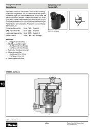
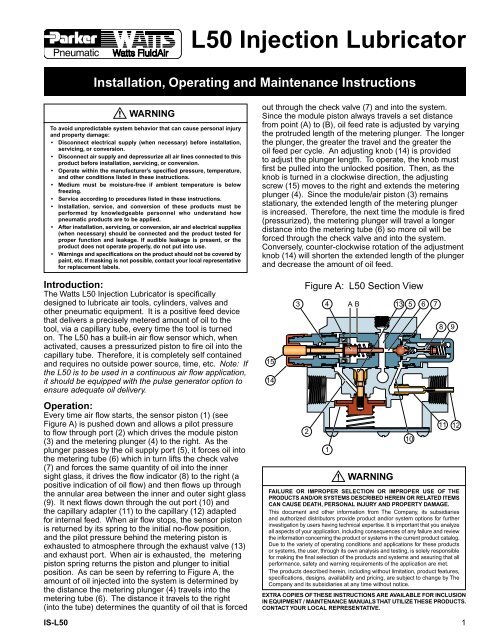
Operation:<br />
Every time air flow starts, the sensor piston (1) (see<br />
Figure A) is pushed down and allows a pilot pressure<br />
to flow through port (2) which drives the module piston<br />
(3) and the metering plunger (4) to the right. As the<br />
plunger passes by the oil supply port (5), it forces oil into<br />
the metering tube (6) which in turn lifts the check valve<br />
(7) and forces the same quantity of oil into the inner<br />
sight glass, it drives the flow indicator (8) to the right (a<br />
positive indication of oil flow) and then flows up through<br />
the annular area between the inner and outer sight glass<br />
(9). It next flows down through the out port (10) and<br />
the capillary adapter (11) to the capillary (12) adapted<br />
for internal feed. When air flow stops, the sensor piston<br />
is returned by its spring to the initial no-flow position,<br />
and the pilot pressure behind the metering piston is<br />
exhausted to atmosphere through the exhaust valve (13)<br />
and exhaust port. When air is exhausted, the metering<br />
piston spring returns the piston and plunger to initial<br />
position. As can be seen by referring to Figure A, the<br />
amount of oil injected into the system is determined by<br />
the distance the metering plunger (4) travels into the<br />
metering tube (6). The distance it travels to the right<br />
(into the tube) determines the quantity of oil that is forced<br />
<strong>L50</strong> <strong>Injection</strong> <strong>Lubricator</strong><br />
Installation, Operating and Maintenance Instructions<br />
!<br />
WARNING<br />
To avoid unpredictable system behavior that can cause personal injury<br />
and property damage:<br />
• Disconnect electrical supply (when necessary) before installation,<br />
servicing, or conversion.<br />
• Disconnect air supply and depressurize all air lines connected to this<br />
product before installation, servicing, or conversion.<br />
• Operate within the manufacturer’s specified pressure, temperature,<br />
and other conditions listed in these instructions.<br />
• Medium must be moisture-free if ambient temperature is below<br />
freezing.<br />
• Service according to procedures listed in these instructions.<br />
• Installation, service, and conversion of these products must be<br />
performed by knowledgeable personnel who understand how<br />
pneumatic products are to be applied.<br />
• After installation, servicing, or conversion, air and electrical supplies<br />
(when necessary) should be connected and the product tested for<br />
proper function and leakage. If audible leakage is present, or the<br />
product does not operate properly, do not put into use.<br />
• Warnings and specifications on the product should not be covered by<br />
paint, etc. If masking is not possible, contact your local representative<br />
for replacement labels.<br />
out through the check valve (7) and into the system.<br />
Since the module piston always travels a set distance<br />
from point (A) to (B), oil feed rate is adjusted by varying<br />
the protruded length of the metering plunger. The longer<br />
the plunger, the greater the travel and the greater the<br />
oil feed per cycle. An adjusting knob (14) is provided<br />
to adjust the plunger length. To operate, the knob must<br />
first be pulled into the unlocked position. Then, as the<br />
knob is turned in a clockwise direction, the adjusting<br />
screw (15) moves to the right and extends the metering<br />
plunger (4). Since the module/air piston (3) remains<br />
stationary, the extended length of the metering plunger<br />
is increased. Therefore, the next time the module is fired<br />
(pressurized), the metering plunger will travel a longer<br />
distance into the metering tube (6) so more oil will be<br />
forced through the check valve and into the system.<br />
Conversely, counter-clockwise rotation of the adjustment<br />
knob (14) will shorten the extended length of the plunger<br />
and decrease the amount of oil feed.<br />
15<br />
14<br />
Figure A: <strong>L50</strong> Section View<br />
3 4 A B 13 5 6 7<br />
2<br />
1<br />
WARNING<br />
10<br />
8<br />
9<br />
11 12<br />
FAILURE OR IMPROPER SELECTION OR IMPROPER USE OF THE<br />
PRODUCTS AND/OR SYSTEMS DESCRIBED HEREIN OR RELATED ITEMS<br />
CAN CAUSE DEATH, PERSONAL INJURY AND PROPERTY DAMAGE.<br />
This document and other information from The Company, its subsidiaries<br />
and authorized distributors provide product and/or system options for further<br />
investigation by users having technical expertise. It is important that you analyze<br />
all aspects of your application, including consequences of any failure and review<br />
the information concerning the product or systems in the current product catalog.<br />
Due to the variety of operating conditions and applications for these products<br />
or systems, the user, through its own analysis and testing, is solely responsible<br />
for making the final selection of the products and systems and assuring that all<br />
performance, safety and warning requirements of the application are met.<br />
The products described herein, including without limitation, product features,<br />
specifications, designs, availability and pricing, are subject to change by The<br />
Company and its subsidiaries at any time without notice.<br />
EXTRA COPIES OF THESE INSTRUCTIONS ARE AVAILABLE FOR INCLUSION<br />
IN EQUIPMENT / MAINTENANCE MANUALS THAT UTILIZE THESE PRODUCTS.<br />
CONTACT YOUR LOCAL REPRESENTATIVE.<br />
IS-<strong>L50</strong> 1<br />
!