L50 Injection Lubricator - Parker
L50 Injection Lubricator - Parker
L50 Injection Lubricator - Parker

You also want an ePaper? Increase the reach of your titles
YUMPU automatically turns print PDFs into web optimized ePapers that Google loves.
Pneumatic Division<br />
Richland, Michigan 49083<br />
269-629-5000<br />
Introduction<br />
Follow these instructions when installing, operating, or servicing the<br />
product.<br />
Application Limits<br />
These products are intended for use in general purpose compressed<br />
air systems only.<br />
Operating Pressure Range:<br />
<strong>Lubricator</strong>s w/ Plastic Bowls<br />
kPa PSIG bar<br />
Maximum<br />
<strong>Lubricator</strong>s w/ Metal Bowls<br />
1034 150 10.34<br />
Maximum 1724 250 17.24<br />
Minimum Flow for Lubrication:<br />
Operating Temperature Range:<br />
1.0 SCFM at 100 PSIG<br />
<strong>Lubricator</strong>s w/ Plastic Bowls -29°C * to 49°C (-20°F to 120°F)<br />
<strong>Lubricator</strong>s w/ Metal Bowls -29°C * to 74°C (-20°F to 165°F)<br />
* Temperatures below 0°C (32°F) require moisture free air.<br />
Suggested Lubricant: F442 Oil<br />
Petroleum based oil of 100 to 200 SUS viscosity at 100°F and<br />
an aniline point greater than 200°F.<br />
(DO NOT USE OILS WITH ADDITIVES, COMPOUNDED<br />
OILS CONTAINING SOLVENTS, GRAPHITE, DETERGENTS,<br />
OR SYNTHETIC OILS.)<br />
Installation:<br />
!<br />
WARNING<br />
To avoid unpredictable system behavior that can cause personal<br />
injury and property damage:<br />
Disconnect electrical supply (when necessary) before<br />
installation, servicing, or conversion.<br />
Disconnect air supply and depressurize all air lines connected<br />
to this product before installation, servicing, or conversion.<br />
Operate within the manufacturer’s specified pressure,<br />
temperature, and other conditions listed in these instructions.<br />
Medium must be moisture-free if ambient temperature is below<br />
freezing.<br />
Service according to procedures listed in these instructions.<br />
Installation, service, and conversion of these products must be<br />
performed by knowledgeable personnel who understand how<br />
pneumatic products are to be applied.<br />
After installation, servicing, or conversion, air and electrical<br />
supplies (when necessary) should be connected and the product<br />
tested for proper function and leakage. If audible leakage is<br />
present, or the product does not operate properly, do not put<br />
into use.<br />
Warnings and specifications on the product should not be<br />
covered by paint, etc. If masking is not possible, contact your<br />
local representative for replacement labels.<br />
1. <strong>Lubricator</strong> should be installed with reasonable accessibility for<br />
service whenever possible — repair service kits are available.<br />
Keep pipe or tubing lengths to a minimum with inside clean and<br />
free of dirt and chips. Pipe joint compound should be used<br />
sparingly and applied only to the male pipe — never into the<br />
female port. Do not use PTFE tape to seal pipe joints — pieces<br />
have a tendency to break off and lodge inside the unit, possibly<br />
causing malfunction. Also new pipe or hose should be installed<br />
between the lubricator and equipment being protected.<br />
2. Install lubricator so that air flows from “IN” to “OUT” as marked<br />
on the lubricator.<br />
3. Installation should be downstream of the filter and regulator but<br />
upstream of the device it is to lubricate (valve, cylinders, tool,<br />
etc.).<br />
4. Install lubricator vertically with bowl drain mechanism at the<br />
bottom. Free moisture will thus drain into the sump (“quiet zone”)<br />
at the bottom of the bowl.<br />
5. Verify that lock ring is installed properly. If it is not, install lock<br />
ring and turn clockwise until it clicks into place. (See Bowl<br />
Replacement for more details.)<br />
ANSI Symbol:<br />
Operation<br />
Installation & Service Instructions:<br />
1L105C<br />
Prep-Air ® I Air Line <strong>Lubricator</strong><br />
ISSUED: November, 2003<br />
Supersedes: January, 2002<br />
Doc.# 1L105, ECN# 030539, Rev. 1<br />
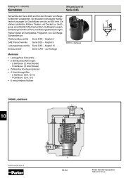
Air flowing through the unit goes through two paths. At low flow<br />
rates the majority of the air flows through the venturi section (A).<br />
The rest of the air opens the flapper (C). The velocity of the air<br />
flowing through the venturi section (A) creates a pressure drop.<br />
This lower pressure allows the oil to be forced from the reservoir<br />
through the pickup tube (B) and travels up to the metering screw<br />
(D). The rate of oil delivery is then controlled by adjusting the<br />
metering screw (D). Oil flows past the metering screw (D) and<br />
forms a drop in the nozzle tube (E). As the oil drops through the<br />
dome (F) and back into the venturi section (A), it is broken up into<br />
fine particles. It is then mixed with the air flowing past the flapper<br />
(C) and is carried downstream. As the air flow increases, the flapper<br />
(C) will open more fully. The additional flow will assure that the oil<br />
delivery rate will increase linearly with the increase of air flow.<br />
To fill lubricator with oil without turning the line pressure off, first<br />
remove the fill plug (G) to relieve pressure from the bowl (H), then<br />
either pour oil through fill plug hole or remove bowl (H) and pour oil<br />
directly into the bowl.<br />
!<br />
WARNING<br />
FAILURE OR IMPROPER SELECTION OR IMPROPER USE OF THE<br />
PRODUCTS AND/OR SYSTEMS DESCRIBED HEREIN OR RELATED<br />
ITEMS CAN CAUSE DEATH, PERSONAL INJURY AND PROPERTY<br />
DAMAGE.<br />
This document and other information from The Company, its subsidiaries<br />
and authorized distributors provide product and/or system options for<br />
further investigation by users having technical expertise. It is important<br />
that you analyze all aspects of your application, including consequences<br />
of any failure and review the information concerning the product or<br />
systems in the current product catalog. Due to the variety of operating<br />
conditions and applications for these products or systems, the user,<br />
through its own analysis and testing, is solely responsible for making<br />
the final selection of the products and systems and assuring that all<br />
performance, safety and warning requirements of the application are<br />
met.<br />
The products described herein, including without limitation, product<br />
features, specifications, designs, availability and pricing, are subject to<br />
change by The Company and its subsidiaries at any time without notice.<br />
EXTRA COPIES OF THESE INSTRUCTIONS ARE AVAILABLE FOR<br />
INCLUSION IN EQUIPMENT / MAINTENANCE MANUALS THAT UTILIZE<br />
THESE PRODUCTS. CONTACT YOUR LOCAL REPRESENTATIVE.