L50 Injection Lubricator - Parker
L50 Injection Lubricator - Parker
L50 Injection Lubricator - Parker

Create successful ePaper yourself
Turn your PDF publications into a flip-book with our unique Google optimized e-Paper software.
L606 <strong>Lubricator</strong> IS-L606<br />
Installation<br />
1. The lubricator should be installed with reasonable accessibility<br />
for service whenever possible – repair service kits are available.<br />
Keep pipe or tubing lengths to a minimum with inside clean<br />
and free of dirt and chips. Pipe joint compound should be used<br />
sparingly and applied only to the male pipe – never into the<br />
female port. Do not use PTFE tape to seal pipe joints – pieces<br />
have a tendency to break off and lodge inside the unit, possibly<br />
causing malfunction. Also, new pipe or hose should be installed<br />
between the lubricator and equipment being lubricated.<br />
2. The upstream pipe work must be clear of accumulated dirt and<br />
liquids.<br />
3. Select a lubricator location as close as possible to the equipment<br />
being lubricated and downstream of any pressure regulator.<br />
4. Install lubricator so that air flows in the direction of arrow on<br />
body.<br />
5. Install lubricator vertically with bowl drain mechanism (if supplied)<br />
at the bottom.<br />
Operation and Service<br />
1. Filling — <strong>Lubricator</strong>s can be filled while under pressure and<br />
without shutting down equipment. Slowly remove either fill<br />
plug and fill to 1/4" to top of bowl using correct oil. For proper<br />
automatic fill operation, the oil inlet pressure to lubricator must<br />
be maintained between 10 and 200 PSI above air pressure to<br />
lubricator.<br />
Suggested Lubricant: F442<br />
Petroleum based oil of 100 to 200 SSU viscosity at 100°F and an<br />
aniline point greater than 200°F. (Mobil DTE24 and Sun Company<br />
Sunvis 932 are good examples). Do not use oils with adhesives,<br />
compound oils containing solvents, graphite, detergents or<br />
synthetic oils.<br />
2. Replace the Fill Plug (by turning clockwise) and seat firmly.<br />
Excessive torque is not required. Turn on air supply, if leakage<br />
occurs, DO NOT OPERATE — conduct repairs again. The<br />
lubricator is now ready for setting.<br />
3. Oil Delivery Adjustment — To adjust oil delivery, turn Adjustment<br />
Knob on top of the lubricator.<br />
Leaner — Clockwise<br />
Richer — Counterclockwise<br />
By counting the number of drops per minute in the Sight Dome,<br />
you can adjust to your requirements. Generally, one drop per<br />
minute downstream for every 10 - 15 SCFM flow is satisfactory.<br />
25 drops per minute equals one (1) ounce per hour - volume of<br />
oil passing through the Sight Dome.<br />
NOTE: This is a constant density type lubricator which delivers<br />
a constant ratio of oil air flow. Therefore, if air flow increases<br />
or decreases, oil delivery will be adjusted proportionately.<br />
ONLY IF A DIFFERENT RATIO IS DESIRED SHOULD YOUR<br />
ADJUSTMENT KNOB SETTING BE CHANGED AFTER YOUR<br />
INITIAL SETTING.<br />
4. Cleaning — Erratic lubricator operation or loss of lubrication is<br />
almost always due to dirt (rust, pipe tape, etc.) in the needle valve<br />
or venturi area. To clean, shut off and vent all air line pressure to<br />
the unit being cleaned. In most cases cleaning is needed only in<br />
the oil metering area. Pull off Adjusting Knob and remove Needle<br />
Valve Assembly by turning out large hex nut. Remove Needle<br />
Valve Seat and clean removed parts with alcohol making sure<br />
hole in seat is clear. With a #57 drill, make sure hole in bottom<br />
of sight gauge area is open. Remove Bowl. Clean parts with<br />
soapy water or denatured alcohol but do not use denatured<br />
alcohol on plastic bowl, sight dome or sight gauge. If using<br />
compressed air to blow dry, be sure to wear appropriate eye<br />
protection.<br />
5. After servicing, apply system pressure and check for air leaks. If<br />
leakage occurs, Do Not Operate — conduct servicing again.<br />
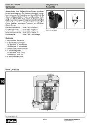
Dip Tube<br />
Check Ball<br />
Button Head<br />
Fill Fitting<br />
Fill Plug<br />
(Brass)<br />
Fill Plug<br />
(Plastic)<br />
Adjusting Knob<br />
Needle Valve<br />
Assembly<br />
Valve Seat<br />
O-ring<br />
Sight Dome<br />
O-ring<br />
Body<br />
O-ring<br />
Collar<br />
(Flange Ring)<br />
Dip Tube<br />
Sight Gauge<br />
Bowl<br />
Lightly grease with provided lubricant.<br />
Inspect for nicks, scratches, and surface imperfections.<br />
If present, reduced service life is probable and future<br />
replacement should be planned.<br />
Clean with lint-free cloth.<br />
Kits Available<br />
Product Bowl Port<br />
Description Number Type Size<br />
Bowl<br />
Polycarbonate BK606Y B 1/4", 3/8"<br />
Zinc with Sight Gauge BK605WY W 1/4", 3/8"<br />
Polycarbonate BK606A B 1/2"<br />
Aluminum BK603A E 1/2"<br />
Zinc with Sight Gauge BK605WA W 1/2"<br />
Aluminum with Sight Gauge BK606X30A G 1/2"<br />
Aluminum BK603B E 3/4" thru 1-1/2"<br />
Zinc with Sight Gauge BK605WB W 3/4" thru 1-1/2"<br />
Aluminum with Sight Gauge<br />
Repair Kit<br />
BK606X30B G 3/4" thru 1-1/2"<br />
Dip Tube Replacement Kit DTK606 All All Sizes<br />
Needle Valve Assembly RK606Y All All Sizes<br />
Sight Dome Repair Kit RK606SY All All Sizes<br />
Sight Gauge Bowl Repair Kit RBK605WY W 1/4", 3/8"<br />
Sight Gauge Bowl Repair Kit RKB605WA W 1/2"<br />
Sight Gauge Bowl Repair Kit RKB606X30A G 1/2"<br />
Sight Gauge Bowl Repair Kit RKB606WB W 3/4" thru 1-1/2"<br />
Sight Gauge Bowl Repair Kit RKB606X30B G 3/4" thru 1-1/2"<br />
Button Head Fill Fitting (3/4 Hex.) SAA606C109-1 — —<br />
Button Head Fill Fitting (11/16 Hex.) L606C14 — —<br />
Fill Plug (Brass) SA606B4 — —<br />
Fill Plug (Plastic) SAP04113 — —