EIB-Interface 500 I/510 I - Somfy
EIB-Interface 500 I/510 I - Somfy
EIB-Interface 500 I/510 I - Somfy

You also want an ePaper? Increase the reach of your titles
YUMPU automatically turns print PDFs into web optimized ePapers that Google loves.
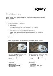
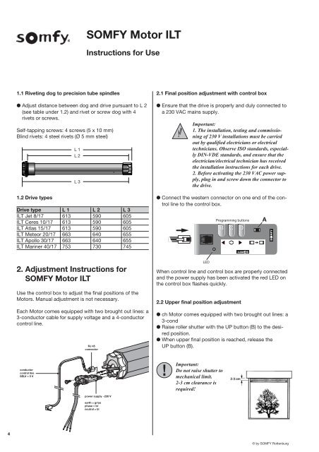
SOMFY Motor ILTInstructions for Use1.1 Riveting dog to precision tube spindles● Adjust distance between dog and drive pursuant to L 2(see table under 1.2) and rivet or screw dog with 4rivets or screws.Self-tapping screws: 4 screws (5 x 10 mm)Blind rivets: 4 steel rivets (Ø 5 mm steel)1.2 Drive typesL 1L 2L 3Drive type L 1 L 2 L 3ILT Jet 8/17 613 590 605ILT Ceres 10/17 613 590 605ILT Atlas 15/17 613 590 605ILT Meteor 20/17 663 640 655ILT Apollo 30/17 663 640 655ILT Mariner 40/17 753 730 7452.1 Final position adjustment with control box● Ensure that the drive is properly and duly connected toa 230 VAC mains supply.Important:1. The installation, testing and commissioningof 230 V installations must be carriedout by qualified electricians or electricaltechnicians. Observe ISO standards, especiallyDIN-VDE standards, and ensure that theelectrician/electrical technician has receivedthe installation instructions for each drive.2. Before activating the 230 VAC power supply,plug in and screw down the connector tothe drive.● Connect the western connector on one end of the controlline to the control box.Programming buttonsB C DA2. Adjustment Instructions forSOMFY Motor ILTUse the control box to adjust the final positions of theMotors. Manual adjustment is not necessary.Each Motor comes equipped with two brought out lines: a3-conductor cable for supply voltage and a 4-conductorcontrol line.RJ 45connectorLEDWhen control line and control box are properly connectedand the power supply has been activated the red LED onthe control box flashes quickly.2.2 Upper final position adjustment● ch Motor comes equipped with two brought out lines: a3-cond● Raise roller shutter with the UP button (B) to the desiredposition.● When upper final position is reached, release theUP button (B).conductorcontrol lineSELV = 5 VImportant:Do not raise shutter tomechanical limit.2-3 cm clearance isrequired!power supply ~230 Vearth = gr/yephase = brneutral = bl4© by SOMFY Rottenburg