EIB-Interface 500 I/510 I - Somfy
EIB-Interface 500 I/510 I - Somfy
EIB-Interface 500 I/510 I - Somfy

You also want an ePaper? Increase the reach of your titles
YUMPU automatically turns print PDFs into web optimized ePapers that Google loves.
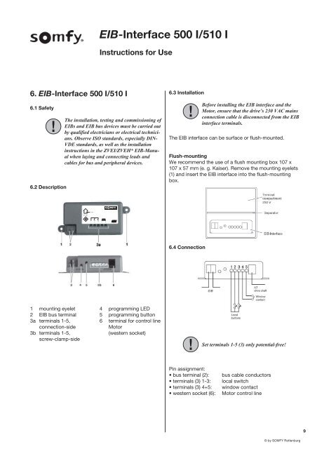
<strong>EIB</strong>-<strong>Interface</strong> <strong>500</strong> I/<strong>510</strong> IInstructions for Use6. <strong>EIB</strong>-<strong>Interface</strong> <strong>500</strong> I/<strong>510</strong> I6.1 Safety6.2 DescriptionThe installation, testing and commissioning of<strong>EIB</strong>s and <strong>EIB</strong> bus devices must be carried outby qualified electricians or electrical technicians.Observe ISO standards, especially DIN-VDE standards, as well as the installationinstructions in the ZVEI/ZVEH* <strong>EIB</strong>-Manualwhen laying and connecting leads andcables for bus and peripheral devices.6.3 InstallationBefore installing the <strong>EIB</strong> interface and theMotor, ensure that the drive’s 230 VAC mainsconnection cable is disconnected from the <strong>EIB</strong>interface terminals.The <strong>EIB</strong> interface can be surface or flush-mounted.Flush-mountingWe recommend the use of a flush mounting box 107 x107 x 57 mm (e. g. Kaiser). Remove the mounting eyelets(1) and insert the <strong>EIB</strong> interface into the flush-mountingbox.IP 205V / 29V1 2 3 4 56.4 Connection1 mounting eyelet 4 programming LED2 <strong>EIB</strong> bus terminal 5 programming button3a terminals 1-5, 6 terminal for control lineconnection-sideMotor3b terminals 1-5,(western socket)screw-clamp-sideSet terminals 1-5 (3) only potential-free!Pin assignment:• bus terminal (2):• terminals (3) 1-3:• terminals (3) 4+5:• western socket (6):bus cable conductorslocal switchwindow contactMotor control line9© by SOMFY Rottenburg