150/250 Wheel Balancer - aesco
150/250 Wheel Balancer - aesco
150/250 Wheel Balancer - aesco

Create successful ePaper yourself
Turn your PDF publications into a flip-book with our unique Google optimized e-Paper software.
<strong>150</strong>/<strong>250</strong> <strong>Wheel</strong> <strong>Balancer</strong>TECHNICAL CHARACTERISTICSMetricEnglishDimensionsMax height (with cover open) 1800mm 75”Depth (with cover open) 1260mm 71”Width (without adapter) 860mm 50”Width (with adapter) 900mm 34”WeightNet Weight (SBM <strong>150</strong>/<strong>250</strong>) 187 kg 411 lbs.Gross Weight (SBM <strong>150</strong>/<strong>250</strong>) 192 kg 422 lbs.Electrical SupplyPower supply (3 models)115V 1~ 60HzPower0.7 kWPhases 1~Protection IP 22Balancing speed200 rpm at 60HzImbalance reading resolution1/5 g (0.01/0.25 oz)Noise level< 75 dbRANGE OF APPLICATIONSThe <strong>150</strong>/<strong>250</strong> <strong>Balancer</strong> is designed for balancing car wheels up to a weight of 154 lbs. andmotorcycle wheels up to a weight of 44 lbs. The operating capacity of the machine is thefollowing:min/maxRim width 1” – 20”Rim diameter 10” – 26”Max. wheel diameter 900mm 44”Max wheel weight (<strong>150</strong>/<strong>250</strong>) 70 kg 154 lbs.NOTE: The minimum and maximum figures given above refer to the dynamic imbalance on thetwo compensating planes, or to static imbalance alone. Imbalance is indicated in grams in threedigital figures, If readings in ounces are preferred to grams, the transformation can beprogrammed (see “<strong>Wheel</strong> <strong>Balancer</strong> Configuration” section).Kwik-Way Products Inc. 5. 800-553-5953500 57 th Street, Marion, IA 52302 USACopyright 2005 All Rights ReservedEquipment specifications, options and accessories subject to change without notice.
UNPACKING<strong>150</strong>/<strong>250</strong> <strong>Wheel</strong> <strong>Balancer</strong>On receipt of the packed machine, remove the straps (taking care when cutting them) andpacking as in Figure 1. After removing the packing check the machine for missing or damagedparts. If in doubt contact your sales representative or Kwik-Way direct.Please open and inspect the accessories provided.NOTE: Discard all non-biodegradable packaging at the appropriate collection points. Allpackaging materials potentially hazardous to children. Dispose of all materials in a responsibleway.Figure 1LOCATION OF THE MACHINEThe machine must be placed on a solid floor surface, and should not be any closer to a wall orany fixed object than 20”. This is to provide for a safe and ergonomic operation of the machine.Figure 2Figure 2Kwik-Way Products Inc. 6. 800-553-5953500 57 th Street, Marion, IA 52302 USACopyright 2005 All Rights ReservedEquipment specifications, options and accessories subject to change without notice.
INSTALLATION<strong>150</strong>/<strong>250</strong> <strong>Wheel</strong> <strong>Balancer</strong>Check the voltage at the wall outlet to be used to verify voltage supply matches the voltage onthe electrical tag located at the rear of the machine by the cord set.Attach the air supply to the air regulator at the rear of the machine. Check to verify that thereare no air leaks and the regulator is adjusted to 115 psi minimum. (P Model only)MACHINE DESCRIPTIONFigure 3:KEY:A: Main SwitchB: Power Supply CableC: Weight Holder PanelD: Control PanelE: <strong>Wheel</strong> Guard Cover (small cover shown)F: AdapterG. Automatic GaugesH: Brake PedalI: Adapter and Accessories SupportL: Pneumatic Supply (on P version only)Kwik-Way Products Inc. 7. 800-553-5953500 57 th Street, Marion, IA 52302 USACopyright 2005 All Rights ReservedEquipment specifications, options and accessories subject to change without notice.
OPTIONAL ACCESSORIES<strong>150</strong>/<strong>250</strong> <strong>Wheel</strong> <strong>Balancer</strong>Figure 5Key1 504-6276-00 Universal flange mount (with standard nuts)1b 504-6281-00 Universal flange mount (with Kwik-nuts)2 504-6062-00 Spacer plate (truck cone)3 504-6063-00 Truck cone (4.8-6.70”)4 504-6000-00 Truck cone set (includes 504-6062-00/504-6063-00)5 504-6358-00 Motorcycle wheel clampKwik-Way Products Inc. 9. 800-553-5953500 57 th Street, Marion, IA 52302 USACopyright 2005 All Rights ReservedEquipment specifications, options and accessories subject to change without notice.
INSTRUCTIONS FOR USE<strong>150</strong>/<strong>250</strong> <strong>Wheel</strong> <strong>Balancer</strong>CONTROL PANELFigure 6Key1. Data display2. Luminous diode imbalance direction indicators3. Imbalance point (LED)4. Rim distance setting buttons5. Rim diameter setting buttons6. Rim width setting buttons7. Unit of measurement selection button for rim width or diameter (mm/ inch)8. Balancing program selection button (MODE)9. Select user button10. Data increase/decrease buttons11. Data confirm button12. Optimization button13. SPLIT button14. Control functions button (MENU)‣ When the wheel is not being driven by the electrical motor, pressing the brake pedallocks the rotation of the wheel.‣ To read the positions for weight application with the ALUDATA gauge, push the pedalup. Figure 3Kwik-Way Products Inc. 10. 800-553-5953500 57 th Street, Marion, IA 52302 USACopyright 2005 All Rights ReservedEquipment specifications, options and accessories subject to change without notice.
WHEEL BALANCING<strong>150</strong>/<strong>250</strong> <strong>Wheel</strong> <strong>Balancer</strong>Switch the machine on with the main switch.‣ When switched on, the machine displays its software version for a few seconds. After thisthe displays read 0 0. Figure 6 (1)‣ Mount the tire and wheel to be balanced on the spindle using the correct centering cone andadapters and tighten with the Kwik-Nut.‣ To balance a wheel the following data must be entered:a) Select wheel type and balancing program, which is correct for the type of wheel andwhere the placement of weight will be made.b) Set the wheel measurements:1. Nominal width2. Nominal diameter3. Set the distance from the machine to the internal side of the wheel.For more in-depth instructions on entering wheel data, refer to the paragraph on “Setting the<strong>Wheel</strong> Data.”‣ Close the hood to begin the wheel balancing cycle.‣ When the balancing cycle is completed, the machine will automatically brake to a stop.‣ The amount and position of the imbalance is measured and then shown in the left and rightdisplays.‣ The luminous arrows will indicate the direction in which the wheel must be turned to reachthe correct position for balance correction. There are separate indicators for the inside andoutside position.‣ When the green center LED is illuminated, it indicates the correct position where the weightsare to be attached (twelve o’clock).‣ Attach the correct amount of weight and in the position as indicated by the LED’s (inside andoutside planes).‣ Close the hood and run a balance cycle to check that the correction is completed. Thedisplay will now read 000.Kwik-Way Products Inc. 11. 800-553-5953500 57 th Street, Marion, IA 52302 USACopyright 2005 All Rights ReservedEquipment specifications, options and accessories subject to change without notice.
<strong>150</strong>/<strong>250</strong> <strong>Wheel</strong> <strong>Balancer</strong>SELECTING BALANCING PROGRAMThe use of different types of counterweights for balancing different types of wheels (in steel orlight alloy) results in variations in the nominal measurements set for the wheel to be balancedand the actual measurements of the correction planes. The wheel balancer offers a variety ofbalancing programs in order to accommodate these differences.The operator must set the operating mode required on the basis of the type of wheel beingbalanced, the type of counterweights to be used, and the selected correction planes.Pressing the MODE button Figure 6 (8) scrolls through all the balancing programs available:‣ Standard dynamic balancing with clip weights (with spring).‣ 5 ALU programs for dynamic balancing with adhesive weights.‣ 3 static balancing programs (with spring or adhesive weights).‣ 2 special ALU programs for balancing PAX Michelin tires with adhesive weights andmeasurements in mm.The LED’s on the control panel indicate the position of weights on the rim on the basis of theselected balancing program.When the machine is switched on it automatically configures itself for the standard dynamicprogram.Kwik-Way Products Inc. 12. 800-553-5953500 57 th Street, Marion, IA 52302 USACopyright 2005 All Rights ReservedEquipment specifications, options and accessories subject to change without notice.
SETTING WHEEL DATA<strong>150</strong>/<strong>250</strong> <strong>Wheel</strong> <strong>Balancer</strong>Setting with the Automatic Gauge‣ Testing is achieved by moving the internal gauge (Figure 7) and external gauge (Figure 8)against the rim. Wait for the confirmation “beep”.‣ The figures to set (distance, width, and diameter) are entered automatically.‣ It is a single, quick, error-free operation.NOTE: If the automatic gauges malfunction (and for the “aluminum” and “light alloy” programs)manual programming is possible (see following section).Figure 7Figure 8Kwik-Way Products Inc. 13. 800-553-5953500 57 th Street, Marion, IA 52302 USACopyright 2005 All Rights ReservedEquipment specifications, options and accessories subject to change without notice.
<strong>150</strong>/<strong>250</strong> <strong>Wheel</strong> <strong>Balancer</strong>SETTING WHEEL DATA (continued)Manual Setting of <strong>Wheel</strong> DataOn the front panel use the +/- buttons to set the figures for width (Figure 6 (6), diameter (Figure6 (5) and distance (Figure 6 (4), for the wheel being balanced.‣ The rim width figures are generally given on the rim itself, otherwise it can be measuredusing the gauge supplied with the machine. Figure 9‣ The rim diameter is generally given on the rim itself, or can be read from the tire.‣ The rim distance is measured on the internal side of the rim with the cursor gauge fitted onthe machine (Figure 10). The distance to be set can be read from the scale.NOTE: For wheels of small dimensions (for example motorcycle wheels) only the staticimbalance has to be established. In these cases the STATIC balancing program is used and thecorrect figures only have to be set for the rim diameter Figure 6 (5). The rim distance and widthcan be set to any figures.Figure 9Figure 10Entering Measurements in mmThe default unit of measurement for rim width and diameter is inches. In order to set wheelmeasurements in mm press the MM/INCH button and enter the figures in mm as they appear onthe wheel. The LED lights up to indicate that the figures are set to mm. Distance is always set inmm (LED on).NOTE: For PAX programs the default unit of measurement of rim width and diameter is mm.Kwik-Way Products Inc. 14. 800-553-5953500 57 th Street, Marion, IA 52302 USACopyright 2005 All Rights ReservedEquipment specifications, options and accessories subject to change without notice.
<strong>150</strong>/<strong>250</strong> <strong>Wheel</strong> <strong>Balancer</strong>USING ALUDATA THE PROGRAMSelecting Balancing ProgramPressing the MODE button opens the program selection page.The ALUDATA programs are:3. ALU 24. ALU 39. Pax 2Select the ALUDATA mode balancing program. When the most suitable balancing program hasbeen selected, press the OK or STOP button to return to the main page.Setting <strong>Wheel</strong> Data‣ When the inside gauge is extracted from its rest position the LED for the selected positionstarts flashing on the control panel.‣ Position the gauge in the first position selected for balancing, keep it still and lift the pedal upto confirm the position. The corresponding panel LED flashes for the selected position. If thepedal is not enabled wait for the confirmation “beep”.‣ Next, locate the gauge at the second position selected for balancing, keep it still and lift thepedal up to confirm the position. The corresponding panel LED flashes for the selectedposition. If the pedal is not enabled wait for the confirmation “beep”.‣ Finally, moving the gauge back to the rest position returns automatically to the main page.<strong>Wheel</strong> Balancing‣ Close the guard cover and press the START button to begin a measuring cycle.‣ When the readings have been established the wheel will automatically brake until it stops.‣ The scale and position of imbalance on the two sides of the wheel are established in asingle measuring cycle and are shown separately on the displays.‣ The arrows indicate the direction the wheel must be turned for the positioning at the point ofimbalance (separate indications for the two sides of the wheel).‣ Turn the wheel manually until the imbalance point LED lights up. Figure 6 (1). If the soundsignal is enabled it also indicates when the correct position is reached.‣ Insert the required adhesive weight into the relevant seat on the measuring probe with theadhesive part facing up. Remove the protective film, extract the probe towards the balancingposition. The arm is automatically stopped when the correct position is reached. Rotate thegauge to bring the weight into contact with the rim and press the extruder to fit the weight..During this stage the LED relative to the selected position for the application of the weight willflash on the panel and the display shows the position of the arm in relation to the selectedbalancing planes.When the correct balancing position is reached the displays show a symbol corresponding tothe conditions:‣ The wheel is in the correct angular position for balancing.‣ The arm is positioned on the corresponding balancing plane.In these conditions the arm is automatically locked in the correct position and the weight can befitted.Kwik-Way Products Inc. 15. 800-553-5953500 57 th Street, Marion, IA 52302 USACopyright 2005 All Rights ReservedEquipment specifications, options and accessories subject to change without notice.
<strong>150</strong>/<strong>250</strong> <strong>Wheel</strong> <strong>Balancer</strong>USING ALUDATA THE PROGRAM (continued)NOTE. The arm does not lock if:‣ It is moved too quickly.‣ It has not been moved far enough away from its last locking position.‣ The wheel is not in position.Repeat operations E and F for the opposite side.NOTE: In the WEIGHT SEPARATION program, the E and F operations must be repeated forboth weights to be fitted on the outside in the correct positions behind the spokes.PROGRAMMING AND FITTING ADHESIVE WEIGHTS WITH THESPECIAL GAUGE FOR ALUMINUM OR LIGHT ALLOY RIMSFigure 11KeyA: Gauge Base CursorB: Weight Positioning Gauge HeadC: Outside ClawD: Screw KnobE: Scale Plate in MillimetersF: ExtruderG: Inside Claw for Fixing WeightsH: Grip with Scale Plate InsertA SPECIAL GAUGE is supplied with the machine for the ALU programs and for fixing weights toaluminum and light alloy rims.This gauge, designed for use in the ALU 2, ALU 3 and Pax 2 programs, allows maximumprecision (also in relation to the rim shape) when determining the position for attaching adhesiveweights.Kwik-Way Products Inc. 16. 800-553-5953500 57 th Street, Marion, IA 52302 USACopyright 2005 All Rights ReservedEquipment specifications, options and accessories subject to change without notice.
<strong>150</strong>/<strong>250</strong> <strong>Wheel</strong> <strong>Balancer</strong>PROGRAMMING AND FITTING ADHESIVE WEIGHTS WITH THESPECIAL GAUGE FOR ALUMINUM OR LIGHT ALLOY RIMS(continued)Look at Figures 11, 12 and 13. Proceed as follows:‣ Set the machine program to ALU 2. Figure 6.‣ Position the gauge with its base at (A) on the inside edge of the rim.‣ Slide the base A on the millimeter scale (E) and move the outside claw (C) to the requiredand optimum position for fixing the weight.‣ Fix the base (A) using the screw knob (D).‣ Read the measurement in mm and enter it as the rim width using the keyboard.‣ Run a balancing cycle: the weight figures are given (internal and external).‣ Move the wheel into position and locate the weight (as read on the external display) on theoutside claw (C).‣ Move the base (A) to the edge of the rim (12 o’clock) and fix the weight using the extruder(F). Figure 12‣ Move the wheel into position and locate the weight (as given on the internal display) on theinside claw (G).‣ Move the gauge head (B) to the edge of the rim and attach the weight using the extruder(F). Figure 13NOTE: For the ALU-3 program the external procedure is the same, while for the internalreading, attach the clip-on weight on the rim flange.Figure 12Figure 13Kwik-Way Products Inc. 17. 800-553-5953500 57 th Street, Marion, IA 52302 USACopyright 2005 All Rights ReservedEquipment specifications, options and accessories subject to change without notice.
SPLIT WEIGHT PROGRAM<strong>150</strong>/<strong>250</strong> <strong>Wheel</strong> <strong>Balancer</strong>The Split Weight Program can be used in the Alu 2 and Alu 3 portions of the Balancing ProgramSelections. To select either ALU 2 or ALU 3, press the Program Selection Key (Figure 6 (8)until the LED combination for the program you wish to use is illuminated on the wheel diagram(center of the display panel). Figure 14.Figure 14NOTE: Be sure that the PAX LED is NOT illuminated when selection is made.Once the ALU 2 or ALU 3 program is selected, proceed as follows:Establish the Weight Placement Locations:‣ Move the inside data arm slowly toward the inside flange of the wheel. The inside LED onthe wheel diagram will begin to flash, continue to move the arm until it is in the correctposition for the weight placement. Lift up on the brake pedal, the LED will stop flashing andbecome solid, the inside position is set.‣ The outside LED will now begin flashing, continue to move the internal data arm inward intothe wheel until the arm is in the correct position for the outside weight placement. Lift up onthe brake pedal, the LED will stop flashing and become solid. The outside position is set.‣ Close the hood and run a cycle.Balancing Procedure:‣ Once the cycle is complete, rotate the tire and wheel, watching the left direction indicators(Figure 6(2), continue until the center green LED (Figure 6(3) is lit.‣ The left display will give the correction weight required for this placement.‣ If in ALU 2 Mode: Slowly move the internal distance arm until the left LED on the wheeldiagram flashes, the arm will stop automatically. Attach the weight.‣ If in the ALU 3 Mode: Simply place clip-on weight at the twelve o’clock position.‣ Press the split weight key (Figure 6 (13); the right display indicates the number of spokesfrom the last balance sequence. If this number is incorrect, use the +- key (Figure 6 (10) toenter the correct number of spokes.‣ Rotate the tire and wheel so as to have a spoke at the twelve o’clock position.‣ Press the split weight key again and one of the LED’s on the key will become illuminated.Rotate the tire and wheel until the right directional indicator green LED is lit. The rightdisplay (Figure 6 (1) will give the correction weight required, move the internal arm in until itlocks, and apply the first weight at this position.‣ Rotate the tire and wheel until the opposite LED on the split weight key becomesilluminated. Continue to rotate the tire and wheel until the right directional indicator greenLED (Figure 6 (3) is lit. The right display (Figure 6 (1) will give the correction weightrequired, move the internal arm in until it locks, and apply the second weight at this point.‣ Close the hood and run a cycle.‣ If tire requires additional weight, repeat the procedure from spoke at the twelve o’clockposition forward.Kwik-Way Products Inc. 18. 800-553-5953500 57 th Street, Marion, IA 52302 USACopyright 2005 All Rights ReservedEquipment specifications, options and accessories subject to change without notice.
OPTIMIZING IMBALANCE<strong>150</strong>/<strong>250</strong> <strong>Wheel</strong> <strong>Balancer</strong>When the imbalance measured on a wheel is very high (e.g., static imbalance > 1.75 ounces)the imbalance optimization procedure is recommended. This program allows the reduction ofthe total imbalance of the wheel by compensating, when possible, the static imbalance of thetire with that of the rim. The following operations are required: an initial measuring cycle,rotation the tire on the rim by 180°, a second measuring cycle, another rotation of the tire on therim to the extent indicated by the machine, and a final check measuring cycle.To activate the static imbalance reduction procedure press the OPTIMIZATION button (Figure 6(12) and release it immediately: the display reads oPt1.Stage 1: Press the START button to run the first cycle with the wheel to be optimized: at theend of the cycle the display reads oPt2.Stage 2: Rotate the wheel by hand to bring the valve to the twelve o’clock position. Press theSPLIT key (which has both LED’s on) to memorize the wheel reference position for the first run.The display reads oPt3. Mark a reference point on the tire itself at the valve position.Stage 3: Remove the rim from the adapter and rotate the tire on the rim by 180° (refer to themark made on the tire, moving it to a position directly opposite the valve). Remount the rim onthe adapter and once more reposition the valve at 12 o’clock. Keeping the wheel in this position,press the SPLIT key (which has both LED’s on) to memorize the new position of the rim on theadapter. The display reads oPt 4.Stage 4: Press the START button to run a new cycle. At the end of the cycle the display readsoPt5.IMPORTANT: For best imbalance reduction results it is important that the operations describedabove are carried out with the maximum precision. Pressing the STOP button at the end of thesecond cycle displays the following information:‣ Right display: current static imbalance reading for the wheel.‣ Left display: minimal residual imbalance that can be achieved by applying the recommendedimbalance reduction.Displaying these figures is useful for deciding if it is worth continuing the imbalance reductionprocedure (for the same reason, also after the first cycle the STOP button can be pressed toview the static imbalance on the right display and thus check if it is effectively worth followingthe reduction procedure).Stage 5: To proceed with reduction of imbalance, rotate the wheel by hand to bring thepositioning LED’s on the display into a central position and mark the tire at the top (the sameposition the weight is normally located). To reduce imbalance remove the rim from the adapterand rotate the tire on the rim until the new mark is at the valve position. Remount the rim on theadapter and again position the valve at twelve o’clock. Keeping the wheel in this position pressthe SPLIT key (with both LED’s on) to memorize the new position of the rim on the adapter. Thedisplay reads oPt 6.Kwik-Way Products Inc. 19. 800-553-5953500 57 th Street, Marion, IA 52302 USACopyright 2005 All Rights ReservedEquipment specifications, options and accessories subject to change without notice.
<strong>150</strong>/<strong>250</strong> <strong>Wheel</strong> <strong>Balancer</strong>OPTIMIZING IMBALANCE (continued)Stage 6: Press the START key to run a test cycle. At the end of the test cycle the wheelimbalance is automatically compared with the minimum residual imbalance figure. If thedifference between these two values is less that the maximum permitted tolerance, the displayreads oPt yES. By pressing the STOP button it is in any case possible to display the new staticimbalance figure in order to verify the success of the procedure.Stage 7: If the first imbalance reduction cycle has not been satisfactory, the display again readsoPt 5. In this case it is possible to continue imbalance reduction by repeating the stepsdescribed above, starting from Stage 5. When it is not possible to further reduce imbalance theprocedure terminates:‣ If the procedure was completed with success the display reads oPt yES.‣ If the procedure was unsuccessful the display reads oPt Err indicating that it is necessary torepeat the entire procedure from the beginning.At the end of optimization operations press the STOP button to return to wheel imbalancemeasuring and the display shows the imbalance for the current wheel.Pressing the OPTIMIZATION button at any time interrupts the imbalance reduction procedureand the system reverts to wheel imbalance measuring mode.Kwik-Way Products Inc. 20. 800-553-5953500 57 th Street, Marion, IA 52302 USACopyright 2005 All Rights ReservedEquipment specifications, options and accessories subject to change without notice.
<strong>150</strong>/<strong>250</strong> <strong>Wheel</strong> <strong>Balancer</strong>BALANCER CONFIGURATIONThe configuration program allows the user to customize the machine according to their ownrequirements.Press and hold the MENU button. As soon as SEt appears in the left display, immediatelyrelease the button. The machine enters the customizing program, which allows the followingparameters to be set.The functions will appear as follows:Zeroing Small Grams. The left display will read toL and the right display gives the currentsetting in the corresponding unit measurement (grams or ounces). To change the setting, usethe keys on Figure 6 (10). The highest setting is 25.0 grams or 1 ounce.Press the OK/MENU button to move to the next parameter.Imbalance Display Interval. The left display reads rES and the right display reads the currentimbalance resolution setting in grams or in ounces depending on the unit of measurementprogrammed. To change the setting, use the keys on Figure 6 (10).The possible settings in grams are:1: Imbalance displayed is the fine resolution, or at an interval of 1 g.5: Imbalance displayed is the standard resolution, or at an interval of 5 gThe possible settings in ounces are:0.05: imbalance displayed is the fine resolution, or at an interval of 0.05 ounces.0.25: imbalance: displayed is the standard resolution, or at an interval of 0.25 ounces.Press the OK/MENU button to move to the next parameter.Imbalance Unit of Measurement: The display reads unb and the right display gives thecurrent imbalance unit of measurement. To change the setting, use the keys on Figure 6 (10).GrA: display currently reads in gramsOun: display currently reads in ouncesPress the OK/MENU button to move to the next parameter.Sound Signal: The left display reads Snd and the right display gives the current state, enabledor disabled, of the sound system.The possible settings are:On: sound signal enabledOFF: sound signal is disabledPress the OK/MENU button to move to the next parameter.Start Up By Lowering Guard: The left display reads CAr and a menu opens with the enabledor disabled for activation with the guard lowered. To change the settings, use the keys onFigure 6 (10).The possible settings are:On: start by simply lowering the guardOFF: start by pressing the START button with the guard in the lowered position.Press the OK/MENU button to move to the next parameter.Kwik-Way Products Inc. 21. 800-553-5953500 57 th Street, Marion, IA 52302 USACopyright 2005 All Rights ReservedEquipment specifications, options and accessories subject to change without notice.
<strong>150</strong>/<strong>250</strong> <strong>Wheel</strong> <strong>Balancer</strong>BALANCER CONFIGURATION (continued)<strong>Wheel</strong> Width Display Interval: The left display shows Lar and the right display shows thepresent value of the width in inches. Use the keys on Figure 6 (10) to introduce a new value.The possible values are:0.50: displays the value in ½” increments0.25: displays the width values in ¼” incrementsPress the OK/MENU button to move to the next parameter.NOTE: To save changes in the parameters, you must press the OK/MENU button. If the STOPbutton is pressed before confirming the new setting, or if the unit is switched off, the machinewill revert back to its previous settings.BASIC MACHINE CALIBRATIONPress and hold down the MENU button.As soon as the left display reads CAL immediately release the button and press (within 1.5 sec)the MM/INCH button.The left display reads C-1.NOTE: Use of the MENU button now permits you to scroll through the various calibrationmenus and choose the one for shaft imbalance calibration (C-1), wheel balancer self-calibration(C-2), or calibration of the automatic gauges (D-1). To exit a menu at any time press STOP.First Stage of Calibration: Shaft Imbalance Correction:‣ Have the bell flange attached to the spindle, but without adapters or tire and wheel.‣ Run a balancing cycle.‣ At the end of the run the measured imbalance is saved. This allows any residual imbalancein the machine’s shaft to be compensated electronically.The left display now reads C-2.Second Stage of Calibration: <strong>Wheel</strong> <strong>Balancer</strong> Self-Calibration:‣ Install a 5.5” or 6.0” wide, 13” or 14” diameter tire and steel wheel assembly onto the spindleand tighten into place using the correct centering cone and adapters.‣ Carefully set the tire and wheel dimensions using the corresponding pairs of buttons Figure6 (4,5,6,10). (Manually enter data.)‣ Run a balancing cycle.‣ C-3 will appear on the left display, 100 or 3.50 on the right. Using the 100g (3.5 ounces)calibration weight provided, attach it to the inside wheel flange.NOTE: The 100 or 3.50 is a calibration default setting, if any other value of weight is to be usedduring calibration, using the buttons +/- move the value up or down in the right display until itshows the corrected value of the weight to be used.Kwik-Way Products Inc. 22. 800-553-5953500 57 th Street, Marion, IA 52302 USACopyright 2005 All Rights ReservedEquipment specifications, options and accessories subject to change without notice.
<strong>150</strong>/<strong>250</strong> <strong>Wheel</strong> <strong>Balancer</strong>BASIC MACHINE CALIBRATION (continued)‣ Run a balancing cycle.‣ At the end of the run C-4 will appear on the left display and 100 or 3.50 on the right. Rotatethe tire and wheel until the weight is at the 12:00 o’clock position, then remove and reattachthe weight to outside flange exactly at the 12:00 o’clock position.‣ Run a balancing cycle.‣ C-5 will appear in the left display and the calibration angle in the right, rotate the tire andwheel until the wheel weight is exactly in the 6:00 o’clock position.‣ While holding the wheel in this position, press the Split weight button. Figure 6 (13).The calibration settings are automatically and permanently saved.Two test procedures are necessary to ensure that wheel balancing is conducted accurately.Balancing Accuracy Test:‣ Balance the two sides of a wheel according to the instructions.‣ Artificially create an imbalance by fitting a weight of 50 grams (1.75 ounces) on one side ofthe wheel. The machine should identify this imbalance precisely, both for weight andposition. A reading up to a maximum of 5 g (.25 ounce) is possible for the other side.‣ In order to check the position of the imbalance, turn the wheel to the balancing position asindicated by the arrows on the monitor. In this position the test weight should be verticallybelow the rotation axle (6 o’clock).‣ If there is an obvious angular error the indicators have to be rectified.‣ If there is an unacceptably big weight error on the side with the test weight, or an excessivefigure for the opposite side of the wheel, the machine has to be recalibrated.Centering Precision (Balancing Quality):‣ The wheel balanced in the previous test can be used. Remove the test weight. Release thewheel from the adapter and retighten it, but rotated by about 35°.‣ In a test cycle the imbalance must not exceed a maximum of 10 g (.5 ounce) on each side,15 g (.75 ounce) in the case of particularly heavy wheels. This error is due to the rimcentering tolerance.‣ Precise centering is essential both for this test and during normal balancing operations. Ifthis test run produces a high imbalance reading check the parts used for centering thewheel for wear, play, and dirt.Kwik-Way Products Inc. 23. 800-553-5953500 57 th Street, Marion, IA 52302 USACopyright 2005 All Rights ReservedEquipment specifications, options and accessories subject to change without notice.
DATA ARM CALIBRATION<strong>150</strong>/<strong>250</strong> <strong>Wheel</strong> <strong>Balancer</strong>To enter the data arm program, press the MENU key (14), and then within 1.5 seconds, pressthe IN/MM key (Item 7).Cal 1 will appear in the left display, press the MENU key again until:‣ D-1 appears in the left display.‣ Using the +- key (Item 10) enter the number to match the beginning number on the internaldistance arm.‣ Move the arm back to the retract position and then press OK (Item 11).Figure 15NOTE: Each graduation on the internal arm scale is one mm. The “beginning number” for thisarm is 3 mm. Your beginning number may be different, it is important to use the correctbeginning number.D-2 appears in the left display.‣ Move the arm to the full extended position, and while holding in that position, use the +/- key(Item 10) and enter the number which appears on the scale, press OK (Item 11).Kwik-Way Products Inc. 24. 800-553-5953500 57 th Street, Marion, IA 52302 USACopyright 2005 All Rights ReservedEquipment specifications, options and accessories subject to change without notice.
<strong>150</strong>/<strong>250</strong> <strong>Wheel</strong> <strong>Balancer</strong>DATA ARM CALIBRATION (continued)Figure 16L-1 appears in the left display.‣ Move the external distance arm to the right position (Figure 16) and while holding it inposition, measure the distance from the stop surfaces on the contact points of the internaland external arms in mm. While still holding the armL-2 appears in the left display.‣ Move the external distance arm to the left position and while holding it in position, measurethe distance from the stop surfaces on the contact points of the internal and external arms inmm. While holding the arm in the aligned position, use the +/- key (Item 10) enter thatmeasurement and press OK (Item 11).Figure 17H-1 appears in the left display.‣ Mount a 14 inch tire and wheel, move the internal arm into position for measuring wheeldiameter, while holding in position. Using the +/- key (Item 10) enter the diameter of thewheel and press OK (Item 11). Figure 17C-2 appears on the left screen.Data arm calibration is complete and data is saved.Kwik-Way Products Inc. 25. 800-553-5953500 57 th Street, Marion, IA 52302 USACopyright 2005 All Rights ReservedEquipment specifications, options and accessories subject to change without notice.
AUTO-DIAGNOSIS<strong>150</strong>/<strong>250</strong> <strong>Wheel</strong> <strong>Balancer</strong>Auto-diagnostic functions are included to check that the balancing machine is working properly.Press and hold down the MENU button.As soon as tSt appears on the left display, immediately release the button and press (within 1.5sec) the MM/INCH button. This opens the auto-diagnosis menu with the following functions(press the MENU button to scroll through the functions):Pick-up voltage display (recorded during the last measuring cycle): the display reads MSr. Todisplay the figures for the last measurement press the distance button on Figure 6 (4). The rightdisplay shows the sequence of readings from the inside pick-up, the outside pick-up, (from 0 to4095), the phase difference (in °), and the gain employed.To check on pick-up operation, proceed as follows:‣ Mount a test wheel on the machine and balance it perfectly.‣ Fit a single test weight on the outside (e.g. 100 g or 3.5 ounces) and run a test cycle.When completed, check the readings. The inside pick-up voltage figure must always be lowerthan the outside pick-up voltage figure. Also, the ratio (outside ÷ inside = 1.2 to 1.8) between theoutside and inside pick-up figures must always be between 1.2 and 1.8. The phase differencemust be 180° ± 1°.Shaft Angular Position Display:The display reads EnC. When the shaft is rotated, the right display varies constantly from 0 to255 or from 0 to 200, depending on the model.Shaft Speed Check:The display reads SP. By pressing the START button it is possible to check the machinerunning speed in rpm (200±5rpm @ 60Hz).Reading Signals:To scroll through the menus use the buttons. Figure 6 (4 and 5). The left display reads insequence An0, An1, …, An10; figures from 0 to 4095. Pressing the + button moves to theanalogue input readings for DISTANCE, WIDTH, and DIAMETER in the corresponding units ofmeasurement.Cycle Counter:The display reads Cnt. To display the cycle count press the distance button (Figure 6 (4) andthe right display gives in sequence the total number of cycles and partial number of cycles (fromthe last time the machine was switched on).Test Display:The display reads LEd; test lighting up of LED’s. To scroll the menus use the distance anddiameter buttons. Figure 6 (4,5).Self-Calibration Data Display:The display reads tAr. To scroll the menus use the buttons. Figure 6 (4, 5).Kwik-Way Products Inc. 26. 800-553-5953500 57 th Street, Marion, IA 52302 USACopyright 2005 All Rights ReservedEquipment specifications, options and accessories subject to change without notice.
<strong>150</strong>/<strong>250</strong> <strong>Wheel</strong> <strong>Balancer</strong>AUTO-DIAGNOSIS (continued)I/O Test:The display reads i_o; various inputs and outputs are rested:‣ Magnet Output: the left display reads mag; the right display reads on if the magnet isactive and oFF if the magnet is inactive.‣ Adapter Enable Output:: the left display reads fla; the right display reads on if theenable output is active and oFF if it is inactive.‣ Pedal Microswitch Input: the left display reads ped; the right display. Reads on ispushed up and oFF if the pedal is in the neutral position.‣ <strong>Wheel</strong> Guard Microswitch Input: the left display reads inP; the right display reads on ifthe guard is closed and oFF if the guard is open.Temporary Balancing of a <strong>Wheel</strong>:‣ The display reads rEL; relative balancing tests can be run on a wheel without actuallybalancing it using counterweights;‣ Mount the test wheel and launch a first cycle; on completion of the cycle the display showsthe real imbalance of the wheel and automatically records the imbalance data and annulsthe same for all subsequent measurements.NOTE: The imbalance figures displayed in all the subsequent measurements after activation ofthis function are not real and are relative to the initial imbalance of the test wheel.This function cannot be memorized and is cancelled when the machine is switched off or byreturning to the same function and pressing the decrease button - : the right display reads on ifthe function is active and oFF if it is inactive.WARNINGSThe present instructions booklet is an integral part of the product. Carefully study the warningsand instructions contained in it. This information is important for safe use and maintenance.Conserve this booklet carefully for further consultation.The <strong>Wheel</strong> <strong>Balancer</strong> SBM <strong>150</strong>/<strong>250</strong> is a machined designed and constructed for the balancing ofcar, van and motorcycle wheels. The machine has been designed to operate within the limitsdescribed in this booklet and in accordance with the manufacturer’s instructions.The machine must be used only for the purpose for which it was expressly designed. Any otheruse is considered wrong and therefore unacceptable. The maker cannot be held responsible foreventual damage caused by improper, erroneous, or unacceptable use.This symbol is used in the present manual to warn the operator of particular risks associatedwith the use of the machine.Kwik-Way Products Inc. 27. 800-553-5953500 57 th Street, Marion, IA 52302 USACopyright 2005 All Rights ReservedEquipment specifications, options and accessories subject to change without notice.
<strong>150</strong>/<strong>250</strong> <strong>Wheel</strong> <strong>Balancer</strong>TROUBLE SHOOTING GUIDEDisplay Malfunctioning Causes TroubleshootingDisplaysdo notcome on.The card is not powered up.1. External supply off or phase notworking.2. Fuse blown in the electrical plant.3. Control panel fuse blown.Err 1 Err 1 appears on power-up. 1. The card has lost the calibrationdata and factory configurationsetting.2. One or more calibration or settingphases have not been carried out.Err 2 During the measuring cycle 1. The guard has been raised beforeErr 3Err 4Err 5Err 6Err 7Err 8the Err 2 message appears.During the measuring cyclethe Err 3 message appears.The motor does not turn(with START pressed) orafter about 20 seconds theErr 4 message appears.At end of second calibratingrun with the wheel Err 5appears on the display.Message Err 6 appearswhen pressing the STARTkey.At end of second calibratingrun with the wheel Err 7appears on the display.At end of second calibratingrun wit the wheel Err 8appears on the display.completion of measurements.1. On start-up (using START key orlowering guard) the wheel wasrotating backwards.2. Motor winding inverted.1. The motor cannot reach therevolutions needed for effectivebalancing.2. Electronic card malfunctioning.3. Electrical plant malfunctioning.1. Calibration weight has not beeapplied on the wheel.2. The pick-ups have not beenconnected.1. The guard has not been lowered.2. Guard microswitch broken.1. Phase difference between the 2pick-ups is too large.1. The left pick-up has not beencorrectly connected or is defectiveor the cable is disconnected.1. Check that positive/negative andneutral are connected up tobalancer.2. Replace fuses in electrical plant(blown fuses; indicate fault inelectric plant).3. Replace fuses on control panel(blown fuses indicate fault inelectronic fault)1. Repeat all calibration and balancerconfiguration stages.2. Perform missing programming orsetting operations.1. Wait for end of measuring launchbefore raising guard.1. Ascertain that the wheel is stillbefore start-up and in any caseavoid rotating wheel backwards onSTART.2. Check for correct motorconnection.1. Check mains voltage (it isprobably low).2. Replace electronic card.3. Replace electrical part.1. Repeat calibration from beginningand apply the calibration weightwhen instructed in the calibrationprocedure. (See “Basic MachineCalibration”)2. Check pick-up connections.1. Lower guard with wheel mounted.2. Replace microswitch.1. Check that the calibration weighthas been correctly applied.2. Check machine location, it isprobably not stable and isvibrating excessively.3. If the problem persists afterhaving stabilized the machinecorrectly, check the sensor andelectronic card connections andreplace if necessary.4. Replace pick-ups.5. If after replacing pick-ups theproblem is not solved, replace thecard.1. Check left pick-up connection andreplace if necessary.Kwik-Way Products Inc. 28. 800-553-5953500 57 th Street, Marion, IA 52302 USACopyright 2005 All Rights ReservedEquipment specifications, options and accessories subject to change without notice.
<strong>150</strong>/<strong>250</strong> <strong>Wheel</strong> <strong>Balancer</strong>TROUBLE SHOOTING GUIDE (continued)Err 9 At end of second calibratingrun with the wheel Err 9appears on the display.Err 10 During launch Err 10appears on the display.Err 11 During launch Err 11appears on the display.Err 17 At end of launch Err 17appears on display.Err 19Err 20Err 21Err 19 is displayed after thesecond calibration cycle.During measuring cycle Err20 appears on display. Thewheel speed has gonebelow the minimum formeasurability.During measuring cycle Err21 appears on display.Possible electrical fault.Err 22 During the launch Err 22appears on display.1. The right pick-u has not beencorrectly connected or is defectiveor the cable is disconnected.1. Position sensors in optoelectronicsdefective.2. The motor will not turn.1. Passage through zero sensorsdefective in optoelectronics.2. The motor will not turn.1. Weight out of regulation field(weight necessary for balancingthe wheel is above 500 grams)1. The signal reading at the rightpick-up is lower than that at theleft pick-up.1. Brake pedal operated during themeasurement.2. Motor rotation speed irregular.1. The electronic card has found acondition of danger connected to atoo high wheel speed during aninactive machine phase.2. The shaft rotates at high speedwithout the operator havingpressed the START command.3. The electric power is deactivated.1. Some fault in the optoelectronicsignals.1. Check right pick-up connectionand replace if necessary.1. Check optoelectronic cardconnection.2. Check the optoelectronic card isprotected from daylight and coverif necessary.3. If the defect persists check and ifnecessary replace theoptoelectronic card.4. Check electrical part.1. Check optoelectronic cardconnection.2. Check the optoelectronic card isprotected from daylight and coverif necessary.3. If the defect persists, check and ifnecessary replace theoptoelectronic card.4. Check the electrical part.1. Check that the wheel is correctlyfixed on the flange.2. Find the external position, apply a100 gram weight and launch a run.1. The connections to the two pickupsmight be inverted. Check andexchange if necessary.1. Avoid pressing the brake pedalwhen the motor is operating.2. Beware of knocking the machineduring the measuring cycle.Check mains voltage – probablylow.1. Switch off the machine, lower theguard and switch the machineback on without moving the wheel.2. If the error persists, check andreplace if necessary the electric orelectronic part (control panel orencoder card).1. Check the optoelectronic card isprotected from daylight and coverif necessary.2. If the defect persists, check and ifnecessary replace theoptoelectronic card.3. Check and if necessary replacethe control panel electronic card.Kwik-Way Products Inc. 29. 800-553-5953500 57 th Street, Marion, IA 52302 USACopyright 2005 All Rights ReservedEquipment specifications, options and accessories subject to change without notice.
ROUTINE MAINTENANCE<strong>150</strong>/<strong>250</strong> <strong>Wheel</strong> <strong>Balancer</strong>To ensure proper operation of the machine, it is essential to perform periodic maintenance.MECHANICAL PARTS: Keep the moving parts of the machine clean, wash them with naphthaor a similar product, lubricate them with oil or grease.LUBRICATOR: Check and maintain the oil level in the lubricator, the level must always bewithin the min/max listed on the outside.TECHNICAL ASSISTANCE AND SPARE PARTSFor any malfunctions, consult the Troubleshooting Guide in this manual. Any malfunctions otherthan those listed should be checked by a qualified technician. For prompt assistance, pleasehave the machine mode and serial number ready when you place your call.Any SPARE PARTS must be ordered from Kwik-Way Products or an authorized distributor themanufacturer denies all responsibility for damage or malfunctions resulting from use of nonoriginalsubstituted parts.Kwik-Way Products Inc. 30. 800-553-5953500 57 th Street, Marion, IA 52302 USACopyright 2005 All Rights ReservedEquipment specifications, options and accessories subject to change without notice.
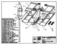
<strong>150</strong>/<strong>250</strong> <strong>Wheel</strong> <strong>Balancer</strong>PART NUMBER REFERENCESKwik-Way Products Inc. 31. 800-553-5953500 57 th Street, Marion, IA 52302 USACopyright 2005 All Rights ReservedEquipment specifications, options and accessories subject to change without notice.
<strong>150</strong>/<strong>250</strong> <strong>Wheel</strong> <strong>Balancer</strong>PART NUMBER REFERENCESKwik-Way Products Inc. 32. 800-553-5953500 57 th Street, Marion, IA 52302 USACopyright 2005 All Rights ReservedEquipment specifications, options and accessories subject to change without notice.
<strong>150</strong>/<strong>250</strong> <strong>Wheel</strong> <strong>Balancer</strong>PART NUMBER REFERENCESKwik-Way Products Inc. 33. 800-553-5953500 57 th Street, Marion, IA 52302 USACopyright 2005 All Rights ReservedEquipment specifications, options and accessories subject to change without notice.
<strong>150</strong>/<strong>250</strong> <strong>Wheel</strong> <strong>Balancer</strong>PART NUMBER REFERENCES(OPTIONALS)Kwik-Way Products Inc. 34. 800-553-5953500 57 th Street, Marion, IA 52302 USACopyright 2005 All Rights ReservedEquipment specifications, options and accessories subject to change without notice.
<strong>150</strong>/<strong>250</strong> <strong>Wheel</strong> <strong>Balancer</strong>ELECTRIC DIAGRAM (115V)Kwik-Way Products Inc. 35. 800-553-5953500 57 th Street, Marion, IA 52302 USACopyright 2005 All Rights ReservedEquipment specifications, options and accessories subject to change without notice.
Kwik-Way Products Inc.500 57 th St., Marion, IA 52302 USA319/377-9421319/377-9101 (FAX)800/553-5953www.kwik-way.comservice@kwik-way.com