150/250 Wheel Balancer - aesco
150/250 Wheel Balancer - aesco
150/250 Wheel Balancer - aesco

Create successful ePaper yourself
Turn your PDF publications into a flip-book with our unique Google optimized e-Paper software.
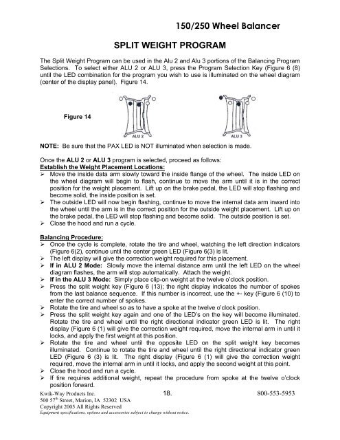
SPLIT WEIGHT PROGRAM<strong>150</strong>/<strong>250</strong> <strong>Wheel</strong> <strong>Balancer</strong>The Split Weight Program can be used in the Alu 2 and Alu 3 portions of the Balancing ProgramSelections. To select either ALU 2 or ALU 3, press the Program Selection Key (Figure 6 (8)until the LED combination for the program you wish to use is illuminated on the wheel diagram(center of the display panel). Figure 14.Figure 14NOTE: Be sure that the PAX LED is NOT illuminated when selection is made.Once the ALU 2 or ALU 3 program is selected, proceed as follows:Establish the Weight Placement Locations:‣ Move the inside data arm slowly toward the inside flange of the wheel. The inside LED onthe wheel diagram will begin to flash, continue to move the arm until it is in the correctposition for the weight placement. Lift up on the brake pedal, the LED will stop flashing andbecome solid, the inside position is set.‣ The outside LED will now begin flashing, continue to move the internal data arm inward intothe wheel until the arm is in the correct position for the outside weight placement. Lift up onthe brake pedal, the LED will stop flashing and become solid. The outside position is set.‣ Close the hood and run a cycle.Balancing Procedure:‣ Once the cycle is complete, rotate the tire and wheel, watching the left direction indicators(Figure 6(2), continue until the center green LED (Figure 6(3) is lit.‣ The left display will give the correction weight required for this placement.‣ If in ALU 2 Mode: Slowly move the internal distance arm until the left LED on the wheeldiagram flashes, the arm will stop automatically. Attach the weight.‣ If in the ALU 3 Mode: Simply place clip-on weight at the twelve o’clock position.‣ Press the split weight key (Figure 6 (13); the right display indicates the number of spokesfrom the last balance sequence. If this number is incorrect, use the +- key (Figure 6 (10) toenter the correct number of spokes.‣ Rotate the tire and wheel so as to have a spoke at the twelve o’clock position.‣ Press the split weight key again and one of the LED’s on the key will become illuminated.Rotate the tire and wheel until the right directional indicator green LED is lit. The rightdisplay (Figure 6 (1) will give the correction weight required, move the internal arm in until itlocks, and apply the first weight at this position.‣ Rotate the tire and wheel until the opposite LED on the split weight key becomesilluminated. Continue to rotate the tire and wheel until the right directional indicator greenLED (Figure 6 (3) is lit. The right display (Figure 6 (1) will give the correction weightrequired, move the internal arm in until it locks, and apply the second weight at this point.‣ Close the hood and run a cycle.‣ If tire requires additional weight, repeat the procedure from spoke at the twelve o’clockposition forward.Kwik-Way Products Inc. 18. 800-553-5953500 57 th Street, Marion, IA 52302 USACopyright 2005 All Rights ReservedEquipment specifications, options and accessories subject to change without notice.