150/250 Wheel Balancer - aesco
150/250 Wheel Balancer - aesco
150/250 Wheel Balancer - aesco
Create successful ePaper yourself
Turn your PDF publications into a flip-book with our unique Google optimized e-Paper software.
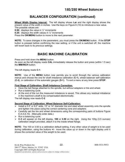
<strong>150</strong>/<strong>250</strong> <strong>Wheel</strong> <strong>Balancer</strong>BALANCER CONFIGURATION (continued)<strong>Wheel</strong> Width Display Interval: The left display shows Lar and the right display shows thepresent value of the width in inches. Use the keys on Figure 6 (10) to introduce a new value.The possible values are:0.50: displays the value in ½” increments0.25: displays the width values in ¼” incrementsPress the OK/MENU button to move to the next parameter.NOTE: To save changes in the parameters, you must press the OK/MENU button. If the STOPbutton is pressed before confirming the new setting, or if the unit is switched off, the machinewill revert back to its previous settings.BASIC MACHINE CALIBRATIONPress and hold down the MENU button.As soon as the left display reads CAL immediately release the button and press (within 1.5 sec)the MM/INCH button.The left display reads C-1.NOTE: Use of the MENU button now permits you to scroll through the various calibrationmenus and choose the one for shaft imbalance calibration (C-1), wheel balancer self-calibration(C-2), or calibration of the automatic gauges (D-1). To exit a menu at any time press STOP.First Stage of Calibration: Shaft Imbalance Correction:‣ Have the bell flange attached to the spindle, but without adapters or tire and wheel.‣ Run a balancing cycle.‣ At the end of the run the measured imbalance is saved. This allows any residual imbalancein the machine’s shaft to be compensated electronically.The left display now reads C-2.Second Stage of Calibration: <strong>Wheel</strong> <strong>Balancer</strong> Self-Calibration:‣ Install a 5.5” or 6.0” wide, 13” or 14” diameter tire and steel wheel assembly onto the spindleand tighten into place using the correct centering cone and adapters.‣ Carefully set the tire and wheel dimensions using the corresponding pairs of buttons Figure6 (4,5,6,10). (Manually enter data.)‣ Run a balancing cycle.‣ C-3 will appear on the left display, 100 or 3.50 on the right. Using the 100g (3.5 ounces)calibration weight provided, attach it to the inside wheel flange.NOTE: The 100 or 3.50 is a calibration default setting, if any other value of weight is to be usedduring calibration, using the buttons +/- move the value up or down in the right display until itshows the corrected value of the weight to be used.Kwik-Way Products Inc. 22. 800-553-5953500 57 th Street, Marion, IA 52302 USACopyright 2005 All Rights ReservedEquipment specifications, options and accessories subject to change without notice.


