


Create successful ePaper yourself
Turn your PDF publications into a flip-book with our unique Google optimized e-Paper software.
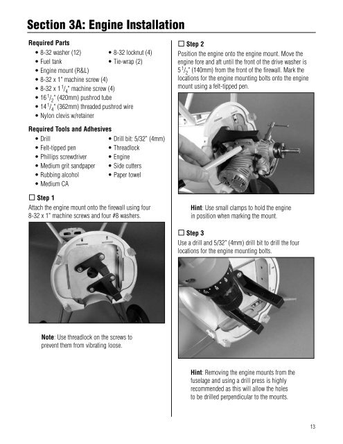
Section 3A: Engine InstallationRequired Parts• 8-32 washer (12) • 8-32 locknut (4)• Fuel tank • Tie-wrap (2)• Engine mount (R&L)• 8-32 x 1" machine screw (4)• 8-32 x 1 1 / 4" machine screw (4)• 16 1 / 2" (420mm) pushrod tube• 14 1 / 4" (362mm) threaded pushrod wire• Nylon clevis w/retainer Step 2Position the engine onto the engine mount. Move theengine fore and aft until the front of the drive washer is5 1 / 2" (140mm) from the front of the firewall. Mark thelocations for the engine mounting bolts onto the enginemount using a felt-tipped pen.Required Tools and Adhesives• Drill• Drill bit: 5/32” (4mm)• Felt-tipped pen• Threadlock• Phillips screwdriver • Engine• Medium grit sandpaper • Side cutters• Rubbing alcohol • Paper towel• Medium CA Step 1Attach the engine mount onto the firewall using four .8-32 x 1" machine screws and four #8 washers.Hint: Use small clamps to hold the enginein position when marking the mount. Step 3Use a drill and 5/32" (4mm) drill bit to drill the fourlocations for the engine mounting bolts.Note: Use threadlock on the screws toprevent them from vibrating loose.Hint: Removing the engine mounts from thefuselage and using a drill press is highlyrecommended as this will allow the holesto be drilled perpendicular to the mounts.13


