


You also want an ePaper? Increase the reach of your titles
YUMPU automatically turns print PDFs into web optimized ePapers that Google loves.
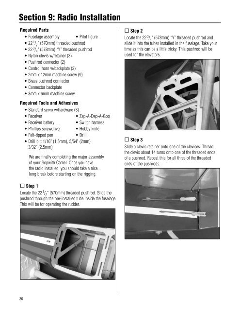
Section 9: Radio InstallationRequired Parts• Fuselage assembly • Pilot figure• 22 1 / 2" (570mm) threaded pushrod• 22 3 / 4" (578mm) “Y” threaded pushrod• Nylon clevis w/retainer (3)• Pushrod connector (2)• Control horn w/backplate (3)• 2mm x 12mm machine screw (9)• Brass pushrod connector• Connector backplate• 3mm x 6mm machine screwRequired Tools and Adhesives• Standard servo w/hardware (3)• Receiver• Zap-A-Dap-A-Goo• Receiver battery• Switch harness• Phillips screwdriver • Hobby knife• Felt-tipped pen• Drill• Drill bit: 1/16" (1.5mm), 5/64" (2mm), .3/32" (2.5mm)We are finally completing the major assemblyof your <strong>Sopwith</strong> <strong>Camel</strong>. Once you havethe radio installed, you should take a nicelong break before starting on the rigging. Step 2Locate the 22 3 / 4" (578mm) “Y” threaded pushrod andslide it into the tubes installed in the fuselage. Take yourtime as this can be a little tricky. This pushrod will beused for the elevators. Step 3Slide a clevis retainer onto one of the clevises. Thread .the clevis about 14 turns onto one of the threaded ends .of a pushrod. Repeat this for all three of the threaded .ends of the pushrods. Step 1Locate the 22 1 / 2" (570mm) threaded pushrod. Slide thepushrod through the pre-installed tube inside the fuselage.This will be for operating the rudder.36


