

Compressive Sensing system for recording of ECoG signals in-vivo
Compressive Sensing system for recording of ECoG signals in-vivo
Compressive Sensing system for recording of ECoG signals in-vivo

Create successful ePaper yourself
Turn your PDF publications into a flip-book with our unique Google optimized e-Paper software.
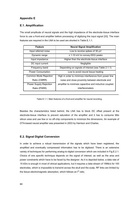
Appendix EE.1. AmplificationThe small amplitude <strong>of</strong> neural <strong>signals</strong> and the high impedance <strong>of</strong> the electrode-tissue <strong>in</strong>terface<strong>for</strong>ce to use a front-end amplifier be<strong>for</strong>e process<strong>in</strong>g <strong>of</strong> digitiz<strong>in</strong>g the <strong>in</strong>put signal [33]. The ma<strong>in</strong>features are required <strong>in</strong> the LNA to be used are shorted <strong>in</strong> Table E.1.1.FeatureNeural Signal AmplificationInput referred noiseLow to revolve spikes <strong>of</strong> 30 μVDynamic range± 1-10 mV to convey EEG peaksInput impedanceHigher than the electrode-tissue <strong>in</strong>terfaceDC <strong>in</strong>put currentNegligibleFrequency band Depend<strong>in</strong>g on <strong>signals</strong> <strong>of</strong> <strong>in</strong>terest (see Table 2.1.1)Power ConsumptionLow to avoid neural tissue heat<strong>in</strong>gCommon Mode Rejection High <strong>in</strong> order to m<strong>in</strong>imize <strong>in</strong>terference from power l<strong>in</strong>eRatio (CMRR)noise and close proximity between electrode andPower Supply Rejection amplifier to m<strong>in</strong>imize capacitive and <strong>in</strong>ductive coupledRatio (PSRR)<strong>in</strong>terferometersTable E.1.1. Ma<strong>in</strong> features <strong>of</strong> a front-end amplifier <strong>for</strong> neural <strong>record<strong>in</strong>g</strong>.Besides the characteristics listed beh<strong>in</strong>d, the LNA has to block DC <strong>of</strong>fset present at theelectrode-tissue <strong>in</strong>terface to prevent saturation <strong>of</strong> the amplifier and it has to consume littlesilicon area and use few or no <strong>of</strong>f-chip components to m<strong>in</strong>imize the dimensions. An example <strong>of</strong>OTA-based neural amplifier was presented <strong>in</strong> 2003 by Harrison and Charles.E.2. Signal Digital ConversionIn order to achieve a robust transmission <strong>of</strong> the <strong>signals</strong> which have been registered, theamplified and eventually compressed <strong>in</strong><strong>for</strong>mation has to be digitized. There is an extensivevariety <strong>of</strong> techniques <strong>for</strong> per<strong>for</strong>m<strong>in</strong>g analog-to-digital conversion which are <strong>in</strong>cluded <strong>in</strong> Fig.E.2.1.Choice <strong>of</strong> one specific technique depends on the signal <strong>of</strong> <strong>in</strong>terest, as well as the area andpower constra<strong>in</strong>ts which have to be faced by the designer. As it is depicted below, a data rate <strong>of</strong>15 kS/s is enough <strong>in</strong> most <strong>of</strong> cl<strong>in</strong>ical applications, but it requires a data stream <strong>of</strong> 15Mb/s <strong>for</strong> 100electrodes, which is impossible to transmit across the skull and the scalp. RF l<strong>in</strong>ks are limited bythe tissue electromagnetic absorption, which follows an f 2 ratio.84


