ADC1251 Self-Calibrating 12-Bit Plus Sign A/D Converter with ...
ADC1251 Self-Calibrating 12-Bit Plus Sign A/D Converter with ...
ADC1251 Self-Calibrating 12-Bit Plus Sign A/D Converter with ...

Create successful ePaper yourself
Turn your PDF publications into a flip-book with our unique Google optimized e-Paper software.
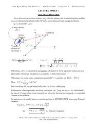
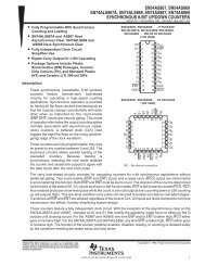
<strong>ADC<strong>12</strong>51</strong> <strong>Self</strong>-<strong>Calibrating</strong> <strong>12</strong>-<strong>Bit</strong> <strong>Plus</strong> <strong>Sign</strong>AD <strong>Converter</strong> <strong>with</strong> Sample-and-HoldGeneral DescriptionThe <strong>ADC<strong>12</strong>51</strong> is a CMOS <strong>12</strong>-bit plus sign successive approximationanalog-to-digital converter On request the<strong>ADC<strong>12</strong>51</strong> goes through a self-calibration cycle that adjustsfor any zero full scale or linearity errors The <strong>ADC<strong>12</strong>51</strong> alsohas the ability to go through an Auto-Zero cycle that correctsthe zero error during every conversionDecember 1994Y 8-bit mPDSP interfaceY Bipolar input range <strong>with</strong> a single a5V referenceY No missing codes over temperatureY TTLMOS inputoutput compatibleKey SpecificationsY Resolution <strong>12</strong> bits plus signThe analog input to the <strong>ADC<strong>12</strong>51</strong> is tracked and held by theY Conversion Time 8 ms (max)internal circuitry so an external sample-and-hold is not requiredY Sampling Rate 83 kHz (max)The <strong>ADC<strong>12</strong>51</strong> has an SH control input which direct-Y Linearity Error g06 LSB (g00146%) (max)ly controls the track-and-hold state of the AD A unipolar Y Zero Error g1 LSB (max)analog input voltage range (0 to a5V) or a bipolar range Y Full Scale Error g15 LSB (max)(b5V to a5V) can be accommodated <strong>with</strong> g5V suppliesY Power Consumption g5V 113 mW (max)The 13-bit data result is available on the eight outputs of the<strong>ADC<strong>12</strong>51</strong> in two bytes high-byte first and sign extendedApplicationsThe digital inputs and outputs are compatible <strong>with</strong> TTL orY Digital signal processingCMOS logic levelsY High resolution process controlYFeaturesInstrumentationY <strong>Self</strong>-calibration provides excellent temperature stabilitySimplified Block DiagramTRI-STATE is a registered trademark of National Semiconductor CorporationTLH11024–1Connection DiagramDual-In-Line PackageTop ViewTLH11024–2Ordering InformationIndustrial(b40C s T As a85C)<strong>ADC<strong>12</strong>51</strong>BIJ<strong>ADC<strong>12</strong>51</strong>CIJPackageJ24AMilitaryPackage(b55C s T As a<strong>12</strong>5C)<strong>ADC<strong>12</strong>51</strong>CMJ<strong>ADC<strong>12</strong>51</strong>CMJ883J24A<strong>ADC<strong>12</strong>51</strong> <strong>Self</strong>-<strong>Calibrating</strong> <strong>12</strong>-<strong>Bit</strong> <strong>Plus</strong> <strong>Sign</strong> AD <strong>Converter</strong> <strong>with</strong> Sample-and-HoldC1995 National Semiconductor CorporationTLH11024RRD-B30M115Printed in U S A
Absolute Maximum Ratings (Notes<strong>12</strong>)If MilitaryAerospace specified devices are requiredplease contact the National Semiconductor SalesOfficeDistributors for availability and specificationsSupply Voltage (V CC e DV CC e AV CC )65VNegative Supply Voltage (V b )b65VVoltage at Logic Control Inputs b03V to (V CC a03V)Voltage at Analog Inputs(V REF V IN ) (V b b03V) to (V CC a03V)AV CC -DV CC (Note 7)03VInput Current at Any Pin (Note 3)g5mAPackage Input Current (Note 3)g20 mAPower Dissipation at 25C (Note 4)875 mWStorage Temperature Rangeb65Ctoa150CESD Susceptability (Note 5)2000VSoldering InformationJ Package (10 sec)300COperating Ratings (Notes<strong>12</strong>)Temperature RangeT MINs T As T MAX<strong>ADC<strong>12</strong>51</strong>BIJ <strong>ADC<strong>12</strong>51</strong>CIJ b40C s T As a85C<strong>ADC<strong>12</strong>51</strong>CMJb55C s T As a<strong>12</strong>5C<strong>ADC<strong>12</strong>51</strong>CMJ883b55C s T As a<strong>12</strong>5CDV CC and AV CC Voltage(Notes67)45V to 55VNegative Supply Voltage (V b )b45V to b55VReference Voltage(V REF Notes67) 35V to AV CC a50 mV<strong>Converter</strong> Electrical CharacteristicsThe following specifications apply for V CC e DV CC e AV CC e a50V V b eb50V V REF e a50V AZ e ‘‘1’’ f CLK e35 MHz and tested using WR control unless otherwise specified Boldface limits apply for T A e T J e T MIN to T MAX all otherlimits T A e T J e 25C (Notes 6 7 and 8)Symbol Parameter ConditionsSTATIC CHARACTERISTICSTypical Limit Units(Note 9) (Notes 10 19) (Limit)Positive Integral <strong>ADC<strong>12</strong>51</strong>BIJ After Auto-Cal g06 LSB(max)Linearity Error<strong>ADC<strong>12</strong>51</strong>CIJ(Notes 11 <strong>12</strong>)g1 LSB(max)<strong>ADC<strong>12</strong>51</strong>CMJ g1 LSB(max)Negative Integral <strong>ADC<strong>12</strong>51</strong>BIJ After Auto-Cal g06 LSB(max)Linearity Error<strong>ADC<strong>12</strong>51</strong>CIJ(Notes 11 and <strong>12</strong>)g1 LSB(max)<strong>ADC<strong>12</strong>51</strong>CMJ g1 LSB(max)Missing Codes After Auto-Cal (Notes 11 and <strong>12</strong>) 0Zero Error (Notes <strong>12</strong> and 13) AZ e ‘‘0’’ and f CLK e 175 MHz g2 LSB(max)After Auto-Cal Only g20g30 LSB(max)Positive Full-Scale Error (Note <strong>12</strong>) AZ e ‘‘0’’ and f CLK e 175 MHz g15 LSB(max)After Auto-Cal Only g15g20 LSB(max)Negative Full-Scale Error (Note <strong>12</strong>) AZ e ‘‘0’’ and f CLK e 175 MHz g15 LSB(max)After Auto-Cal Only g15g20 LSB(max)C REF V REF Input Capacitance (Note 18) 80 pFC IN Analog Input Capacitance 65 pFV IN Analog Input Voltage V b b 005 V(min)V CC a 005 V(max)Power Supply Sensitivity Zero Error (Note 14) AV CC e DV CC e 5V g5% g LSBFull-Scale Error V REF e 475V Vb eb5V g5% g LSBLinearity Error g LSB2
<strong>Converter</strong> Electrical Characteristics (Continued)The following specifications apply for V CC e DV CC e AV CC e a50V V b eb50V V REF e a50V AZ e ‘‘1’’ and f CLKe 35 MHz unless otherwise specified Boldface limits apply for T A e T J e T MIN to T MAX all other limits T A e T J e 25C(Notes 6 7 and 8)Symbol Parameter ConditionsDYNAMIC CHARACTERISTICSTypical Limit Units(Note 9) (Notes 10 19) (Limit)S(NaD) Unipolar <strong>Sign</strong>al-to-NoiseaDistortion f IN e 1 kHz V IN e 485 V p-p 72 dBRatio (Note 17)f IN e 20 kHz V IN e 485 V p-p 72 dBS(NaD) Bipolar <strong>Sign</strong>al-to-NoiseaDistortion f IN e 1 kHz V IN e g485V 76 dBRatio (Note 17)f IN e 20 kHz V IN e g485V 76 dBb3 dB Unipolar Full Power Bandwidth V IN e 485V (Note 17) 32 kHzb3 dB Bipolar Full Power Bandwidth V IN e g485V (Note 17) 25 kHzt Ap Aperture Time 100 nsAperture Jitter 100 ps rmsDigital and DC Electrical CharacteristicsThe following specifications apply for DV CC e AV CC ea50V V b eb50V V REF ea50V and f CLK e 35 MHz unlessotherwise specified Boldface limits apply for T A e T J e T MIN to T MAX all other limits T A e T J e 25C (Notes 6 and 7)Symbol Parameter ConditionsV IN(1) Logical ‘‘1’’ Input Voltage for V CC e 525VAll Inputs except CLK INV IN(0) Logical ‘‘0’’ Input Voltage for V CC e 475VAll Inputs except CLK INTypical Limit Units(Note 9) (Notes 10 19) (Limit)2008V(min)V(max)I IN(1) Logical ‘‘1’’ Input Current V IN e 5V 0005 1 mA(max)I IN(0) Logical ‘‘0’’ Input Current V IN e 0V b0005 b1 mA(max)V TaV TbV HCLK IN Positive-GoingThreshold VoltageCLK IN Negative-GoingThreshold VoltageCLK IN HysteresisV a T (min) b V b T (max)28 27 V(min)21 23 V(max)07 04 V(min)V OUT(1) Logical ‘‘1’’ Output Voltage V CC e 475VI OUT eb360 mA 24 V(min)I OUT eb10 mA 45 V(min)V OUT(0) Logical ‘‘0’’ Output Voltage V CC e 475VI OUT e 16 mA04V(max)I OUT TRI-STATE Output Leakage V OUT e 0V b001 b3 mA(max)CurrentV OUT e 5V 001 3 mA(max)I SOURCE Output Source Current V OUT e 0V b20 b60 mA(min)I SINK Output Sink Current V OUT e 5V 20 80 mA(min)DI CC DV CC Supply Current CS e ‘‘1’’ 1 25 mA(max)AI CC AV CC Supply Current CS e ‘‘1’’ 4 10 mA(max)I b V b Supply Current CS e ‘‘1’’ 28 10 mA(max)3
AC Electrical CharacteristicsThe following specifications apply for DV CC e AV CC e a50V V b e b50V t r e t f e 20 ns unless otherwise specifiedBoldface limits apply for T A e T J e T MIN to T MAX all other limits T A e T J e 25C (Notes 6 and 7)Symbol Parameter ConditionsTypical Limit Units(Note 9) (Notes 10 19) (Limit)f CLK Clock Frequency MHz05MHz(min)60 35 MHz(max)Clock Duty Cycle 50 %40 %(min)60 %(max)t C Conversion Time Using WR 27(1f CLK ) 27(1f CLK ) a 250 ns (max)to Start a Conversionf CLK e 35 MHz AZ e ‘‘1’’ 77 795 ms(max)f CLK e 175 MHz AZ e ‘‘0’’ 154 1565 ms(max)t C Conversion Time Using SH AZ e ‘‘1’’ 34(1f CLK ) 34(1f CLK ) a 250 ns (max)to Start a Conversionf CLK e 35 MHz AZ e ‘‘1’’ 97 995 ms(max)t A Acquisition Time (Note 15) R SOURCE e 50X 35 35 ms(min)t IAInternal Acquisition Time(When Using WR Control Only)7(1f CLK ) 7(1f CLK ) (max)t ZA Auto Zero Time a Acquisition Time 33(1f CLK ) 33(1f CLK ) a 250 ns (max)f CLK e 175 MHz 188 1905 ms(max)t D(EOC)L Delay from Hold Command Using WR Control 200 350 ns(max)to Falling Edge of EOCUsing SH Control 100 150 ns(max)t CAL Calibration Time 1399(1f CLK ) 1399 (1f CLK ) (max)f CLK e 35 MHz 399 400 ms(max)t W(CAL)L Calibration Pulse Width (Note 16) 60 200 ns(min)t W(WR)L Minimum WR Pulse Width 60 200 ns(min)t ACC Maximum Access Time C L e 100 pF(Delay from Falling Edge of 50 95 ns(max)RD to Output Data Valid)t 0H t 1H TRI-STATE Control R L e 1kXC L e100 pF(Delay from Rising Edge of 30 70 ns(max)RD to Hi-Z State)t PD(INT) Maximum Delay from Falling Edgeof RD or WR to Reset of INT100 175 ns(max)t RR Delay between Successive RD Pulses 30 60 ns(min)Note 1 Absolute Maximum Ratings indicate limits beyond which damage to the device may occur Operating Ratings indicate conditions for which the device isfunctional but do not guarantee specific performance limits For guaranteed specifications and test conditions see the Electrical Characteristics The guaranteedspecifications apply only for the test conditions listed Some performance characteristics may degrade when the device is not operated under the listed testconditionsNote 2 All voltages are measured <strong>with</strong> respect to AGND and DGND unless otherwise specifiedNote 3 When the input voltage (V IN ) at any pin exceeds the power supply rails (V INk V b or V INl (AV CC or DV CC ) the current at that pin should be limited to5 mA The 20 mA maximum package input current rating allows the voltage at any four pins <strong>with</strong> an input current limit of 5 mA to simultaneously exceed the powersupply voltagesNote 4 The power dissipation of this device under normal operation should never exceed 191 mW (Quiescent Power Dissipation a 1 TTL Load on each digitaloutput) Caution should be taken not to exceed absolute maximum power rating when the device is operating in severe fault condition (ex when any inputs oroutputs exceed the power supply) The maximum power dissipation must be derated at elevated temperatures and is dictated by T Jmax (maximum junctiontemperature) i JA (package junction to ambient thermal resistance) and T A (ambient temperature) The maximum allowable power dissipation at any temperatureis P Dmax e (T Jmax b T A )i JA or the number given in the Absolute Maximum Ratings whichever is lower For this device T Jmax e 150C and the typical thermalresistance (i JA ) of the <strong>ADC<strong>12</strong>51</strong> <strong>with</strong> CMJ BIJ and CIJ suffixes when board mounted is 51CWNote 5 Human body model 100 pF discharged through a 15 kX resistor4
Electrical Characteristics (Continued)Note 6 Two on-chip diodes are tied to the analog input as shown below Errors in the AD conversion can occur if these diodes are forward biased more than50 mV This means that if AV CC and DV CC are minimum (475 V DC ) and V b is maximum (b475 V DC ) the analog input full-scale voltage must be s g48 V DC Note 7 A diode exists between AV CC and DV CC as shown belowTLH11024–4TLH11024–5To guarantee accuracy it is required that the AV CC and DV CC be connected together to a power supply <strong>with</strong> separate bypass filters at each V CC pinNote 8 Accuracy is guaranteed at f CLK e 35 MHz At higher or lower clock frequencies accuracy may degrade See the Typical Performance CharacteristicscurvesNote 9 Typicals are at T J e 25C and represent most likely parametric normNote 10 Limits are guaranteed to National’s AOQL (Average Outgoing Quality Level)Note 11 Positive linearity error is defined as the deviation of the analog value expressed in LSBs from the straight line that passes through positive full scale andzero For negative linearity error the straight line passes through negative full scale and zero (See Figures 1b and 1c)Note <strong>12</strong> The <strong>ADC<strong>12</strong>51</strong>’s self-calibration technique ensures linearity full scale and offset errors as specified but noise inherent in the self-calibration process willresult in a repeatability uncertainty of g020 LSBNote 13 If T A changes then an Auto-Zero or Auto-Cal cycle will have to be re-started See the typical performance characteristic curvesNote 14 After an Auto-Zero or Auto-Cal cycle at the specified power supply extremesNote 15 When using the WR control to start a conversion if the clock is asynchronous to the rising edge of WR an uncertainty of one clock period will exist in theend of the interval t A therefore making t A end a minimum 6 clock periods or a maximum 7 clock periods after the rising edge of WR If the falling edge of the clockis synchronous to the rising edge of WR then t A will end exactly 65 clock periods after the rising edge of WR This does not occur when SH control is usedNote 16 The CAL line must be high before a conversion is startedNote 17 The specifications for these parameters are valid after an Auto-Cal cycle has been completedNote 18 The <strong>ADC<strong>12</strong>51</strong> reference ladder is composed solely of capacitorsNote 19 A Military RETS Electrical Test Specification is available on request At time of printing the <strong>ADC<strong>12</strong>51</strong>CMJ883 RETS specification complies fully <strong>with</strong> theboldface limits in this columnFIGURE 1a Transfer CharacteristicTLH11024–65
Electrical Characteristics (Continued)TLH11024–7FIGURE 1b Simplified Error Curve vs Output Code <strong>with</strong>out Auto-Cal or Auto-Zero CyclesFIGURE 1c Simplified Error Curve vs Output Code after Auto-Cal CycleTypical Performance CharacteristicsTLH11024–8Zero Error Change vsAmbient TemperatureZero Error vs V REFLinearity Error vs V REFTLH11024–96
Typical Performance Characteristics (Continued)Linearity Error vsClock FrequencyFull Scale Error Changevs Ambient TemperatureBipolar <strong>Sign</strong>al-to-NoiseaDistortion Ratio vsInput Source ImpedanceBipolar <strong>Sign</strong>al-to-NoiseaDistortion Ratio vsInput FrequencyUnipolar <strong>Sign</strong>al-to-NoiseaDistortion Ratio vsInput FrequencyUnipolar <strong>Sign</strong>al-to-NoiseaDistortion Ratio vsInput <strong>Sign</strong>al LevelBipolar <strong>Sign</strong>al-to-NoiseaDistortion Ratio vsInput <strong>Sign</strong>al LevelBipolar Spectral Response<strong>with</strong> 1 kHz Sine Wave InputBipolar Spectral Response<strong>with</strong> 10 kHz Sine Wave InputBipolar Spectral Response<strong>with</strong> 20 kHz Sine Wave InputBipolar Spectral Response<strong>with</strong> 40 kHz Sine Wave InputUnipolar Spectral Response<strong>with</strong> 1 kHz Sine Wave InputTLH11024–107
Typical Performance Characteristics (Continued)Unipolar Spectral Response<strong>with</strong> 10 kHz Sine Wave InputUnipolar Spectral Response<strong>with</strong> 20 kHz Sine Wave InputUnipolar Spectral Response<strong>with</strong> 40 kHz Sine Wave InputTest CircuitsTLH11024–11TLH11024–13TLH11024–<strong>12</strong>TLH11024–15TLH11024–14FIGURE 2 TRI-STATE Test Circuits and Waveforms8
Timing DiagramsAuto-Cal CycleUsing WR Control to Start a Conversion <strong>with</strong> Auto-Zero (CAL e 1 AZ e 0)TLH11024–16TLH11024–179
Timing Diagrams (Continued)Using WR Control to Start a Conversion <strong>with</strong>out Auto-Zero (CAL e 1 AZ e 1)TLH11024–18Using SH Control to Start a Conversion <strong>with</strong>out Auto-Zero (AZ e 1 CAL e 1)TLH11024–1910
10 Pin DescriptionsDV CC (24) The digital and analog positive power supplyAV CC (4) pins The digital and analog power supplyvoltage range of the <strong>ADC<strong>12</strong>51</strong> is a45V toa55V To guarantee accuracy it is requiredthat the AV CC and DV CC be connected togetherto the same power supply <strong>with</strong> separatebypass capacitors (10 mF tantalum inparallel <strong>with</strong> a 01 mF ceramic) at each V CCpinV b (5) The analog negative supply voltage pin V bhas a range of b45V to b55V and needsbypass capacitors of 10 mF tantalum in parallel<strong>with</strong> a 01 mF ceramicDGND (<strong>12</strong>) The digital and analog ground pins AGNDAGND (3) and DGND must be connected together externallyto guarantee accuracyV REF (2) The reference input voltage pin To maintainaccuracy the voltage at this pin should notexceed the AV CC or DV CC by more than50 mV or go below a35 V DC V IN (1) The analog input voltage pin To guaranteeaccuracy the voltage at this pin should notexceed V CC by more than 50 mV or go belowV b by more than 50 mVCS (10) The Chip Select control input This input isactive low and enables the WR RDand SHfunctionsRD (23) The Read control input With both CS and RDlow the TRI-STATE output buffers are enabledand the INT output is reset highWR (7) The Write control input The conversion isstarted on the rising edge of the WR pulsewhen CS is low When this control line isused the end of the analog input voltage acquisitionwindow is internally controlled by the<strong>ADC<strong>12</strong>51</strong>SH (11) The sample and hold control input This controlinput can also be used to start a conversionWith CS low the falling edge of SHstarts the analog input acquisition windowThe rising edge of SH ends the acquisitionwindow and starts a conversionCLKIN (8) The external clock input pin The typical clockfrequency range is 500 kHz to 60 MHzCAL (9) The Auto-Calibration control input WhenCAL is low the <strong>ADC<strong>12</strong>51</strong> is reset and a calibrationcycle is initiated During the calibrationcycle the values of the comparator offsetvoltage and the mismatch errors in the capacitorreference ladder are determined andstored in RAM These values are used to correctthe errors during a normal cycle of ADconversionAZ (6) The Auto-Zero control input With the AZ pinheld low during a conversion the <strong>ADC<strong>12</strong>51</strong>goes into an auto-zero cycle before the actualAD conversion is started This Auto-Zerocycle corrects for the comparator offset voltageThe total conversion time (t C ) is increasedby 26 clock periods when Auto-Zerois usedEOC (22) The End-of-Conversion control output Thisoutput is low during a conversion or a calibrationcycleINT (21) The Interrupt control output This output goeslow when a conversion has been completedand indicates that the conversion result isavailable in the output latches Reading theresult or starting a conversion or calibrationcycle will reset this output highDB0DB8– The TRI-STATE output pins Twelve bit plusDB7DB<strong>12</strong> sign output data access is accomplished us-(13–20) ing two successive RDs of one byte eachhigh byte first (DB8–DB<strong>12</strong>) The data formatused is two’s complement sign bit extended<strong>with</strong> DB<strong>12</strong> the sign bit DB11 the MSB andDB0 the LSB20 Functional DescriptionThe <strong>ADC<strong>12</strong>51</strong> is a <strong>12</strong>-bit plus sign AD converter <strong>with</strong> thecapability of doing Auto-Zero or Auto-Cal routines to minimizezero full-scale and linearity errors It is a successiveapproximationAD converter consisting of a DAC comparatorand a successive-approximation register (SAR) Auto-Zero is an internal calibration sequence that corrects for theAD’s zero error caused by the comparator’s offset voltageAuto-Cal is a calibration cycle that not only corrects zeroerror but also corrects for full-scale and linearity errorscaused by DAC inaccuracies Auto-Cal minimizes the errorsof the <strong>ADC<strong>12</strong>51</strong> <strong>with</strong>out the need for trimming during itsfabrication An Auto-Cal cycle can restore the accuracy ofthe <strong>ADC<strong>12</strong>51</strong> at any time which ensures accuracy overtemperature and time21 DIGITAL INTERFACEOn power up a calibration sequence should be initiated bypulsing CAL low <strong>with</strong> CS and SH high To acknowledge theCAL signal EOC goes low after the falling edge of CAL andremains low during the calibration cycle of 1399 clock periodsDuring the calibration sequence first the comparator’soffset is determined then the capacitive DAC’s mismatcherrors are found Correction factors for these errors are thenstored in internal RAMA conversion can be initiated by taking CS and WR low IfAZ is low an Auto-Zero cycle which takes approximately 26clock periods is inserted before the analog input is sampledand the actual conversion is started AZ must remain lowduring the complete conversion sequence After Auto-Zerothe acquisition opens and the analog input is sampled forapproximately 7 clock periods If AZ is high the Auto-Zerocycle is not inserted after the rising edge of WR In this casethe acquisition window opens when the <strong>ADC<strong>12</strong>51</strong> completesa conversion signaled by the rising edge of EOC Atthe end of the acquisition window EOC goes low signalingthat the analog input is no longer being sampled and thatthe AD successive approximation conversion has started11
20 Functional Description (Continued)A conversion sequence can also be controlled by the SHand CS inputs Taking CS and SH low starts the acquisitionwindow for the analog input voltage The rising edge of SHimmediately puts the AD in the hold mode and starts theconversion Using SH will simplify synchronizing the end ofthe acquisition window to other signals which may be necessaryin a DSP environmentDuring a conversion the sampled input voltage is successivelycompared to the output of the DAC First the acquiredinput voltage is compared to analog ground to determineits polarity The sign bit is set low for positive inputvoltages and high for negative Next the MSB of the DAC isset high <strong>with</strong> the rest of the bits low If the input voltage isgreater than the output of the DAC then the MSB is lefthigh otherwise it is set low The next bit is set high makingthe output of the DAC three quarters or one quarter of fullscale A comparison is done and if the input is greater thanthe new DAC value this bit remains high if the input is lessthan the new DAC value the bit is set low This processcontinues until each bit has been tested The result is thenstored in the output latch of the <strong>ADC<strong>12</strong>51</strong> Next INT goeslow and EOC goes high to signal the end of the conversionThe result can now be read by taking CS and RD low toenable the DB0DB8–DB7DB<strong>12</strong> output buffers The highbyte of data is relayed first on the data bus outputs asshown belowDB0 DB1 DB2 DB3 DB4 DB5 DB6 DB7DB8 DB9 DB10 DB11 DB<strong>12</strong> DB<strong>12</strong> DB<strong>12</strong> DB<strong>12</strong><strong>Bit</strong> 8 <strong>Bit</strong> 9 <strong>Bit</strong> 10 MSB <strong>Sign</strong> <strong>Bit</strong> <strong>Sign</strong> <strong>Bit</strong> <strong>Sign</strong> <strong>Bit</strong> <strong>Sign</strong> <strong>Bit</strong>Taking CS and RD low a second time will relay the low byteof data on the data bus outputs as shown belowDB0 DB1 DB2 DB3 DB4 DB5 DB6 DB7DB8 DB9 DB10 DB11 DB<strong>12</strong> DB<strong>12</strong> DB<strong>12</strong> DB<strong>12</strong>LSB <strong>Bit</strong> 1 <strong>Bit</strong> 2 <strong>Bit</strong> 3 <strong>Bit</strong> 4 <strong>Bit</strong> 5 <strong>Bit</strong> 6 <strong>Bit</strong> 7The table in Figure 3 summarizes the effect of the digitalcontrol inputs on the function of the <strong>ADC<strong>12</strong>51</strong> The TestMode where RD and SH are high and CS and CAL arelow is used during manufacture to thoroughly check out theoperation of the <strong>ADC<strong>12</strong>51</strong> Care should be taken not to inadvertentlybe in this mode since DB2 DB3 DB5 and DB6become active outputs which may cause data bus contention22 RESETTING THE ADThe <strong>ADC<strong>12</strong>51</strong> is reset whenever a new conversion is startedby taking CS and WR or SH low If this is done when theanalog input is being sampled or when EOC is low theAuto-Cal correction factors may be corrupted therefore requiringan Auto-Cal cycle before the next conversion Whenusing WR or SH <strong>with</strong>out Auto-Zero (AZ e 1) to start aconversion a new conversion can be restarted only afterEOC has gone high signaling the end of the current conversionWhen using WR <strong>with</strong> Auto-Zero (AZ e 0) a new conversioncan be restarted during the first 26 clock periodsafter the rising edge of WR (t Z ) or after EOC has returnedhigh <strong>with</strong>out corrupting the Auto-Cal correction factorsThe Calibration Cycle cannot be reset once started Onpower-up the <strong>ADC<strong>12</strong>51</strong> automatically goes through a CalibrationCycle that takes typically 1399 clock cycles For reasonsthat will be discussed in Section 38 a new calibrationcycle needs to be started after the completion of the automaticone30 Analog Considerations31 REFERENCE VOLTAGEThe voltage applied to the reference input of the converterdefines the voltage span of the analog input (the differencebetween V IN and AGND) over which 4095 positive outputcodes and 4096 negative output codes exist The A-to-Dcan be used in either ratiometric or absolute reference applicationsThe voltage source driving V REF must have avery low output impedance and very low noise The circuit inFigure 4 is an example of a very stable reference that isappropriate for use <strong>with</strong> the <strong>ADC<strong>12</strong>51</strong>CSDigital Control InputsWR SH RD CAL AZAD Function 1 1 1 1 Start Conversion <strong>with</strong>out Auto-Zero 1 1 1 1 Start Conversion synchronous <strong>with</strong> rising edge of SH <strong>with</strong>out Auto-Zero 1 1 1 1 Read Conversion Result <strong>with</strong>out Auto-Zero 1 1 1 0 Start Conversion <strong>with</strong> Auto-Zero 1 1 1 0 Read Conversion Result <strong>with</strong> Auto-Zero1 X 1 X X Start Calibration Cycle0 X X 1 0 X Test Mode (DB2 DB3 DB5 and DB6 become active)FIGURE 3 Function of the AD Control Inputs<strong>12</strong>
30 Analog Considerations (Continued)TantalumCeramicFIGURE 4 Low Drift Extremely Stable Reference CircuitTLH11024–20In a ratiometric system the analog input voltage is proportionalto the voltage used for the AD reference When thisvoltage is the system power supply the V REF pin can betied to V CC This technique relaxes the stability requirementof the system reference as the analog input and AD referencemove together maintaining the same output code for agiven input conditionFor absolute accuracy where the analog input varies betweenvery specific voltage limits the reference pin can bebiased <strong>with</strong> a time and temperature stable voltage sourceIn general the magnitude of the reference voltage will requirean initial adjustment to null out full-scale errors32 ACQUISITION WINDOWAs shown in the timing diagrams there are three differentmethods of starting a conversion each of which affects theacquisition window and timingWith Auto-Zero high a conversion can be started <strong>with</strong> theWR or SH controls In either method of starting a conversionthe rising edge of EOC signals the actual beginning ofthe acquisition window At this time a voltage spike may benoticed on the analog input of the <strong>ADC<strong>12</strong>51</strong> whose amplitudeis dependent on the input voltage and the source resistanceThe timing diagrams for these two methods ofstarting a conversion do not show the acquisition windowstarting at this time because the acquisition time (t A ) muststart after the conversion result high and low bytes havebeen read This is necessary since activating and deactivatingthe digital outputs (DB0DB7–DB8DB<strong>12</strong>) causes currentfluctuations in the <strong>ADC<strong>12</strong>51</strong>’s internal DV CC lines Thisgenerates digital noise which couples into the capacitiveladder that stores the analog input voltage Therefore thetime interval between the rising edge of EOC and the secondread is inappropriate for analog input voltage acquisitionWhen WR is used to start a conversion <strong>with</strong> AZ low theAuto-Zero cycle is inserted before the acquisition window Inthis method the acquisition window is internally controlledby the <strong>ADC<strong>12</strong>51</strong> and lasts for approximately 7 clock periodsSince the acquisition window needs to be at least35 ms at all times when using Auto-Zero the maximumclock frequency is limited to 2 MHz The zero error <strong>with</strong> theAuto-Zero cycle is production tested at a clock frequency of175 MHz This accommodates easy switching between aconversion <strong>with</strong> the Auto-Zero cycle (f CLK e 175 MHz) and<strong>with</strong>out (f CLK e 35 MHz) as shown in Figure 5TLH11024–21FIGURE 5 Switching between a Conversion <strong>with</strong> and<strong>with</strong>out Auto-Zero when Using WR Control33 INPUT CURRENTBecause the input network of the <strong>ADC<strong>12</strong>51</strong> is made up of aswitch and a network of capacitors a charging current willflow into or out of (depending on the input voltage polarity)the analog input pin (V IN ) on the start of the analog inputsampling period The peak value of this current will dependon the actual input voltage applied and the source resistance34 NOISEThe leads to the analog input pin should be kept as short aspossible to minimize input noise coupling Both noise andundesired digital clock coupling to this input can cause errorsInput filtering can be used to reduce the effects ofthese noise sources13
30 Analog Considerations (Continued)35 INPUT BYPASS CAPACITORSAn external capacitor can be used to filter out any noise dueto inductive pickup by a long input lead and will not degradethe accuracy of the conversion result36 INPUT SOURCE RESISTANCEThe analog input can be modeled as shown in Figure 6External R S will lengthen the time period necessary for thevoltage on C REF to settle to <strong>with</strong>in LSB of the analoginput voltage With t A e 35 ms R Ss 1kXwill allow a 5Vanalog input voltage to settle properly37 POWER SUPPLIESNoise spikes on the V CC and V b supply lines can causeconversion errors as the comparator will respond to thisnoise The AD is especially sensitive during the Auto-Zeroor -Cal procedures to any power supply spikes Low inductancetantalum capacitors of 10 mF or greater paralleled<strong>with</strong> 01 mF ceramic capacitors are recommended for supplybypassing Separate bypass capacitors should be placedclose to the DV CC AV CC and V b pins If an unregulatedvoltage source is available in the system a separateLM340LAZ-50 voltage regulator for the A-to-D’s V CC (andother analog circuitry) will greatly reduce digital noise on thesupply line38 THE CALIBRATION CYCLEOn power up the <strong>ADC<strong>12</strong>51</strong> goes through an Auto-Cal cyclewhich cannot be interrupted Since the power supply referenceand clock will not be stable at power up this firstcalibration cycle will not result in an accurate calibration ofthe AD A new calibration cycle needs to be started afterthe power supplies reference and clock have been givenenough time to stabilize During the calibration cycle correctionvalues are determined for the offset voltage of thesampled data comparator and any linearity and gain errorsThese values are stored in internal RAM and used during ananalog-to-digital conversion to bring the overall full scaleoffset and linearity errors down to the specified limits Fullscale error typically changes g02 LSB over temperatureand linearity error changes even less therefore it should benecessary to go through the calibration cycle only once afterpower up if Auto-Zero is used to correct the zero errorchange Since Auto-Zero cannot be activated <strong>with</strong> SH conversionmethod it may be necessary to do a calibration cyclemore than once39 THE AUTO-ZERO CYCLETo correct for any change in the zero (offset) error of theAD the Auto-Zero cycle can be used It may be necessaryto do an Auto-Zero cycle whenever the ambient temperaturechanges significantly (See the curve titled ‘‘Zero ErrorChange vs Ambient Temperature’’ in the Typical PerformanceCharacteristics) A change in the ambient temperaturewill cause the V OS of the sampled data comparator tochange which may cause the zero error of the AD to begreater than g1 LSB An Auto-Zero cycle will maintain thezero error to g1 LSB or less40 Dynamic PerformanceMany applications require the AD converter to digitize ACsignals but the standard DC integral and differential nonlinearityspecifications will not accurately predict the AD converter’sperformance <strong>with</strong> AC input signals The importantspecifications for AC applications reflect the converter’sability to digitize AC signals <strong>with</strong>out significant spectral errorsand <strong>with</strong>out adding noise to the digitized signal Dynamiccharacteristics such as signal-to-noiseadistortion ratio(S(NaD)) effective bits full power bandwidth aperturetime and aperture jitter are quantitative measures of theAD converter’s capabilityAn AD converter’s AC performance can be measured usingFast Fourier Transform (FFT) methods A sinusoidalwaveform is applied to the AD converter’s input and thetransform is then performed on the digitized waveform S(NaD) is calculated from the resulting FFT data and aspectral plot may also be obtained Typical values for S(NaD) are shown in the table of Electrical Characteristicsand spectral plots are included in the typical performancecurvesThe AD converter’s noise and distortion levels will change<strong>with</strong> the frequency of the input signal <strong>with</strong> more distortionand noise occurring at higher signal frequencies This canbe seen in the S(NaD) versus frequency curves Thesecurves will also give an indication of the full power bandwidth(the frequency at which the S(NaD) drops 3 dB)FIGURE 6 Analog Input Equivalent CircuitTLH11024–2214
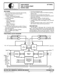
40 Dynamic Performance (Continued)Two samplehold specifications aperture time and aperturejitter are included in the Dynamic Characteristics tablesince the <strong>ADC<strong>12</strong>51</strong> has the ability to track and hold theanalog input voltage Aperture time is the delay for the ADto respond to the hold command In the case of the<strong>ADC<strong>12</strong>51</strong> when using the SH control to start a conversionthe hold command is generated by the rising edge of SHThe delay between the rising edge of SH and the time that50 Typical Applicationsthe <strong>ADC<strong>12</strong>51</strong> actually holds the input signal is the aperturetime For the <strong>ADC<strong>12</strong>51</strong> this time is typically 100 ns Aperturejitter is the change in the aperture time from sample tosample Aperture jitter is useful in determining the maximumslew rate of the input signal for a given accuracy For examplean <strong>ADC<strong>12</strong>51</strong> <strong>with</strong> 100 ps of aperture jitter operating <strong>with</strong>a 5V reference can have an effective gain variation of about1 LSB <strong>with</strong> an input signal whose slew rate is <strong>12</strong> VmsPower Supply BypassingTLH11024–23Protecting the Analog InputsNote External protection diodes should be able to <strong>with</strong>stand the op amp current limitTLH11024–2415
<strong>ADC<strong>12</strong>51</strong> <strong>Self</strong>-<strong>Calibrating</strong> <strong>12</strong>-<strong>Bit</strong> <strong>Plus</strong> <strong>Sign</strong> AD <strong>Converter</strong> <strong>with</strong> Sample-and-HoldPhysical Dimensions inches (millimeters)LIFE SUPPORT POLICYOrder Number <strong>ADC<strong>12</strong>51</strong>CMJ <strong>ADC<strong>12</strong>51</strong>CMJ883 <strong>ADC<strong>12</strong>51</strong>BIJ or <strong>ADC<strong>12</strong>51</strong>CIJNS Package Number J24ANATIONAL’S PRODUCTS ARE NOT AUTHORIZED FOR USE AS CRITICAL COMPONENTS IN LIFE SUPPORTDEVICES OR SYSTEMS WITHOUT THE EXPRESS WRITTEN APPROVAL OF THE PRESIDENT OF NATIONALSEMICONDUCTOR CORPORATION As used herein1 Life support devices or systems are devices or 2 A critical component is any component of a lifesystems which (a) are intended for surgical implant support device or system whose failure to perform caninto the body or (b) support or sustain life and whose be reasonably expected to cause the failure of the lifefailure to perform when properly used in accordance support device or system or to affect its safety or<strong>with</strong> instructions for use provided in the labeling can effectivenessbe reasonably expected to result in a significant injuryto the userNational Semiconductor National Semiconductor National Semiconductor National SemiconductorCorporation Europe Hong Kong Ltd Japan Ltd1111 West Bardin Road Fax (a49) 0-180-530 85 86 13th Floor Straight Block Tel 81-043-299-2309Arlington TX 76017 Email cnjwge tevm2nsccom Ocean Centre 5 Canton Rd Fax 81-043-299-2408Tel 1(800) 272-9959 Deutsch Tel (a49) 0-180-530 85 85 Tsimshatsui KowloonFax 1(800) 737-7018 English Tel (a49) 0-180-532 78 32 Hong KongFranais Tel (a49) 0-180-532 93 58 Tel (852) 2737-1600Italiano Tel (a49) 0-180-534 16 80 Fax (852) 2736-9960National does not assume any responsibility for use of any circuitry described no circuit patent licenses are implied and National reserves the right at any time <strong>with</strong>out notice to change said circuitry and specifications