Download - Northstar
Download - Northstar
Download - Northstar
- No tags were found...

You also want an ePaper? Increase the reach of your titles
YUMPU automatically turns print PDFs into web optimized ePapers that Google loves.
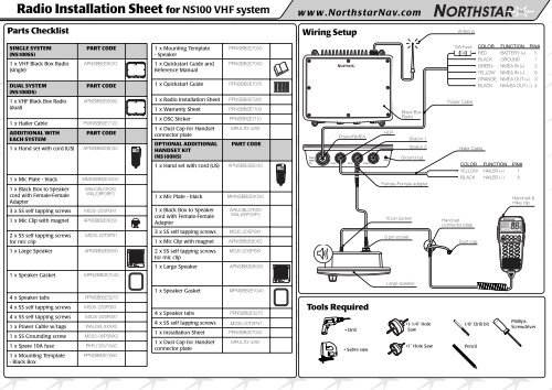
3CH 16/9 CALLSCAN WX FUNC3CH 16/9 CALLSCAN WX FUNCRadio Installation Sheet for NS100 VHF systemParts Checklistwww.<strong>Northstar</strong>Nav.comWiring SetupAntennaSINGLE SYSTEM(NS100SS)1 x VHF Black Box Radio(single)DUAL SYSTEM(NS100DS)1 x VHF Black Box Radio(dual)PART CODEAPNSBB2E8070PART CODEAPNSBB2E80801 x Hailer Cable PWNSBB2E7120ADDITIONAL WITHPART CODEEACH SYSTEM1 x Hand set with cord (US) APNSBB2E80301 x Mic Plate - black MMNSBB2E40001 x Black Box to Speakercord with Female-FemaleAdapterWALI08L07KX0WALI08F08F03 x SS self tapping screws MS35-20SPSX11 x Mic Clip with magnet APNSBB2E80502 x SS self tapping screwsfor mic clipMS35-20TSPX11 x Mounting Template- Speaker1 x Quickstart Guide andReference ManualPPNSBB2E7030PPNSBB2E70501 x Quickstart Guide PPNSBB2E70701 x Radio Installation Sheet PPNSBB2E72601 x Warranty Sheet PPNSBB2E71001 x DSC Sticker PPNSBB2E71101 x Dust Cap for Handsetconnector plateOPTIONAL ADDITIONALHANDSET KIT(NS100HS)MPLILTD-4/80PART CODE1 x Hand set with cord (US) APNSBB2E80301 x Mic Plate - black MMNSBB2E40001 x Black Box to Speakercord with Female-FemaleAdapterWALI08L07KX0WALI08F08F03 x SS self tapping screws MS35-20SPSX11 x Mic Clip with magnet APNSBB2E8050HLRPower/NMEAHLR10 pin socket8 pin socketBlack BoxRadioStation 1Station 2Ground lugFemale-Female adapter10A Fuse10APower CableHailer CableHand setconnector plateCOLOR FUNCTION PIN#RED BATTERY (+) 5BLACK GROUND 1GREEN NMEA IN (+) 2YELLOW NMEA IN (–) 6ORANGE NMEA OUT (+) 3BLACK NMvEA OUT (–) 4COLOR FUNCTION PIN#YELLOW HAILER (+) 1BLACK HAILER (–) 8Dust cap3CH 16/9 CALLSCAN WX FUNCHand set &mike clip1 x Large Speaker APNSBB2E80602 x SS self tapping screwsfor mic clipMS35-20SPSX11 x Large Speaker APNSBB2E80601 x Speaker Gasket MPNSBB2E7040Large speaker4 x Speaker tabs PPNSBB2E32704 x SS self tapping screws MS35-20SPSX14 x SS self tapping screws MS35-20SPSX11 x Power Cable w/tags WALI06LXXXX01 x SS Grounding screw MS30-06PSNX21 x Spare 10A fuse PKFU125V10A01 x Mounting Template- Black BoxPPNSBB2E70801 x Speaker Gasket MPNSBB2E70404 x Speaker tabs PPNSBB2E32704 x SS self tapping screws MS35-20TSPX11 x Installation Sheet PPNSBB2E70301 x Dust Cap for Handsetconnector plateMPLILTD-4/80Tools Required• Drill• Sabre saw•1-1/4” HoleSaw•1” Hole Saw1/8” Drill bitPencilPhillipsScrewdriver
Installation Tips Installing Handset Connector Installing Microphone Clip PlateSpeaker is at least45cms (1.5') fromthe compassBlack Box Radio mustbe at least 1metre (3’)from the Antenna1.2.3.4.5.6.7.Find a location for the Handset connector nearthe vessel steering wheel and check that there isenough wire length to reach the remote speakerlocation. Stretch the mike cord to be sure thehandset is comfortable to use while driving.Using the black metal plate as a guide, mark thecenter of the hole to be drilled.Use a 1” hole saw to cut out the dash.Leaving the small rubber gasket on the backsideof the connector, push it through the D holein the plate. Put the rubber dust cap over theconnector shaft and tighten the nylon nut.Hold the plate & connector assembly to the dashand mark the 3 holes. Use a 1/8” drill. Mount theplate with the 3 screws provided.Connect the handset connector.When removed, be sure to cover the connectorwith the provided dust cap.1.2.3.4.Mount the handset near the mountedconnector allowing a drip loop in the MIKEcord. Be sure there is about 2” of verticalclearance to allow the handset to be easilylifted off and returned to the clip plate.Place the clip plate on the dash with themagnetic sensor toward the rear. Using the clipplate as a guide, mark the 2 holes.Use a 1/8” drill. Mount the clip plate with the 2screws provided.Mount the handset connector.Location Requirements - Please check these before doingany cutting or drilling.Ensure that the chosen location:• is at least one metre (3') from the antenna• allows easy connection to (at least) a 10 Amp fused 12Vonly DC electrical source and the antenna.• is at least 45cms (1.5') from the compass to avoidcreating magnetic deviation of the compass during radiooperation• has a suitable space close by for installing themicrophone bulkhead mount• provides easy access to the front panel controls• provides reasonable access to the wiring at the back ofthe radio.Wiring Hailer Connector1.2.Check that the location of the powerful 20W4 Ohm HAILER HORN (not provided) does noteffect the ship’s compass before drilling holesand mounting. The Horn needs a clear view ofthe bow of the boat so the FOG and PA signalscan be heard well by other vessels.Run 2 #20 AWG wires from the horn to the Boxand connect to the HAILER connector wires.Follow the wire colors on the front of this sheetand crimp to the HAILER connector assemblywiring.CAUTIONNOTE: DO NOT GROUND EITHER SIDE OF THEHAILER WIRES.Installing Remote Speaker1.2.3.4.5.6.Check the location does not effect the ship’scompass before drilling any holes.Using the template provided, use the 1-1/4”hole saw to cut out the 4 corners.Use the sabre saw to trim the remaining insideof the speaker cutout.Use the 1/8” drill bit for the 4 side mountingholes.Mount the speaker with supplied gasket fromthe front and hook up the connectors.. Noneed to get behind the panel.Put the 4 speaker clips on the speaker to coverup the mounting holes for a professional look.PPNSBB2E7080 (L A000406A)