Download - Northstar
Download - Northstar
Download - Northstar
Create successful ePaper yourself
Turn your PDF publications into a flip-book with our unique Google optimized e-Paper software.
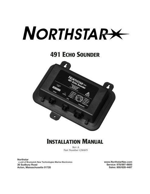
491 ECHO SOUNDERINSTALLATION MANUALRev APart Number GM495<strong>Northstar</strong>a unit of Brunswick New Technologies Marine Electronics30 Sudbury RoadActon, Massachusetts 01720www.<strong>Northstar</strong>Nav.comService: 978/897-6600Sales: 800/628-4487
Table of ContentsSECTION ONE — Introduction - - - - - - - - - - - - - - - - - - - - 1Welcome to the <strong>Northstar</strong> 491 - - - - - - - - - - - - - - - - - 1Who should read this manual - - - - - - - - - - - - - - - - - 1Scope of this manual - - - - - - - - - - - - - - - - - - - - - 1Installation considerations - - - - - - - - - - - - - - - - - - - 2SECTION TWO — Installing the transducer - - - - - - - - - - - - - - 3Safety considerations - - - - - - - - - - - - - - - - - - - - - 3Selecting a transducer - - - - - - - - - - - - - - - - - - - - - 4Installation considerations - - - - - - - - - - - - - - - - - - - 5Choosing a mounting location - - - - - - - - - - - - - - - - - 5Installing the transducer - - - - - - - - - - - - - - - - - - - - 7Maintaining the transducer - - - - - - - - - - - - - - - - - - 8SECTION THREE — Installing the 491 - - - - - - - - - - - - - - - 11Safety considerations - - - - - - - - - - - - - - - - - - - - 11System components - - - - - - - - - - - - - - - - - - - - - 13Choosing a mounting location - - - - - - - - - - - - - - - - 14Mounting the 491 - - - - - - - - - - - - - - - - - - - - - - 14Wiring the 491 - - - - - - - - - - - - - - - - - - - - - - - 15Initial checkout - - - - - - - - - - - - - - - - - - - - - - - 19Installation test checklist - - - - - - - - - - - - - - - - - - 20SECTION FOUR — Troubleshooting and servicing the 491 - - - - - - 21Common 491 installation problems - - - - - - - - - - - - - - 21The status LED - - - - - - - - - - - - - - - - - - - - - - - 21Getting technical support - - - - - - - - - - - - - - - - - - 24Ordering replacement parts - - - - - - - - - - - - - - - - - 25Servicing the 491 - - - - - - - - - - - - - - - - - - - - - - 25Returning a 491 for service - - - - - - - - - - - - - - - - - 26APPENDIX A — Technical specifications - - - - - - - - - - - - - - 27Glossary - - - - - - - - - - - - - - - - - - - - - - - - - - - - - 29Index - - - - - - - - - - - - - - - - - - - - - - - - - - - - - - - 31
SECTION ONE — IntroductionWelcome tothe <strong>Northstar</strong>491An echo sounder is a device that provides information about the waterdirectly beneath a vessel. The <strong>Northstar</strong> echo sounder system consists of:• the <strong>Northstar</strong> 491 echo sounder sensor• a <strong>Northstar</strong> navigation system such as the 962, 958 or 6000i• a transducerThe 491 can be used with either a single-element transducer or adual-element transducer. The 491 automatically pings both transmittersat power-up to determine the number of transducer elements connected.If a single element is detected, the 491 operates in single-frequency ordual-frequency interleaved mode (as determined by the operator) at 600Watts. If two elements are detected, the 491 uses both elements at 1000Watts.Installation and setup procedures are different for the two basic types of<strong>Northstar</strong> navigators. The following terminology should be carefully followed:• the term 961/962 indicates instructions that apply to the <strong>Northstar</strong>961 and the 962 navigators• the term 957/958/6000i is used for these units• the term navigator by itself identifies information that applies to allunitsWho shouldread thismanualThis manual is for marine technicians who are installing the <strong>Northstar</strong>491 and connecting it to a <strong>Northstar</strong> navigator and a transducer.Scope of thismanualIn this manual, you’ll find information about the following:• mounting and wiring the 491• connecting the 491 to the <strong>Northstar</strong> navigator• installing a transducer (an overview is provided, but for such detailsas wiring, see the documentation provided by the transducer’s manufacturer)491 INSTALLATION MANUAL Revision A PAGE 1
SECTION ONE — Introduction• connecting the 491 to a transducer (see also the Transducer ConnectorInstructions—GM492)• troubleshooting and testing the system• technical specifications for the 491For information about obtaining technical support and returning the 491for factory service, “SECTION FOUR — Troubleshooting and servicing the491” beginning on page 21.For details about operating the 491, see the <strong>Northstar</strong> 491 Echo SounderOperations Manual (GM494) or <strong>Northstar</strong> 6000i’s Reference Manual, forthat product.InstallationconsiderationsCAUTION!The following list of installation considerations isn’ta substitute for all the details in Section Three. Toensure that you meet all critical installation parameters,be sure to read that entire section and followall of its recommendations.1. Check the shipping carton for any damage, and immediately reportany damage to the carrier. Save all packing material in case you haveto return the 491 to the factory for repair or evaluation.2. Unpack the carton, and check its contents. You should havereceived:• the <strong>Northstar</strong> 491 Echo Sounder• 10-foot (3-meter) data cable to connect the 491 to the navigator• 10-foot (3-meter) power cable for the 491• 491 parts kit (containing transducer cable end connector, backshell,heatshrink tubing, and the Transducer Connector Instructions—GM492)• <strong>Northstar</strong> 491 Echo Sounder Installation Manual (GM495)• <strong>Northstar</strong> 491 Echo Sounder Operations Manual (GM494)• owner registration card3. Fill out the owner registration card and mail it to <strong>Northstar</strong>.4. Review all of the installation requirements as outlined in SectionsTwo and Three.5. Install the transducer, then terminate the cable (see ”Connecting the491 to a transducer” starting on page 18).6. Mount the 491. For instructions, see ”Mounting the 491” beginningon page 14.7. Connect the 491 to ship’s power and to the navigator. Connectioninformation begins on page 15.With the vessel in the water, turn on the system and verify proper operation.PAGE 2491 INSTALLATION MANUAL Revision A
SECTION TWO — Installing the transducerSafetyconsiderationsWARNING!Be sure to turn the power off before starting theinstallation. Further, it is highly recommended thatyou keep power off while you’re performing theinstallation. If power is left on or turned on duringthe installation, fire, electrical shock, or other seriousinjury may occur.Be sure to ground the equipment to prevent electricalshock and mutual interference.Be sure the transducer outputs are tied togetherbefore handling to avoid electrical charge build-up.WARNING!Be sure to use a 3-amp fuse. Using the incorrectfuse can result in fire or damage to the 491.CAUTION!Mounting the transducer requires drilling holesthrough the hull; make sure the installation doesnot cause the vessel to leak. A thru-hull installationshould be performed by a professional installer. Donot attempt this unless you are fully qualified.Do not perform a thru-hull installation of the transducerwhen the vessel is actually in the water.Immediately after installing the transducer, be sureto check for leaks, and don’t leave the vessel in thewater for more than three hours before checking itagain.<strong>Northstar</strong> assumes no responsibility for improperinstallation of a transducer.NOTE:Be sure that the transducer doesn’t interfere withany of the on-board systems. Check all other systemsto ensure that their performance doesn’tdegrade when the transducer is connected.491 INSTALLATION MANUAL Revision A PAGE 3
SECTION TWO — Installing the transducerSelecting atransducer<strong>Northstar</strong> recommends using an Airmar transducer with the <strong>Northstar</strong>491 echo sounder. The Airmar B260, B744 and P66 can be obtained from<strong>Northstar</strong> as an installation kit with connectors installed.Table 1: <strong>Northstar</strong>-recommended transducersManufacturer Housing Power Frequency <strong>Northstar</strong> P/NAirmar B260 1 kW 50/200 kHz TD1004AirmarB744V/B44V (with3-wire speed)600 W 50/200 kHz TD1005Airmar P66 600 W 50/200 kHz TD1006A table of Airmar transducer elements is given below to assist in evaluatingcharacteristics of other Airmar transducers.Table 2: Airmar transducer elementsTransducerelementSingleor DualelementUsed inAirmarP/NAcousticmaterialBeamWidth(50kHz)BeamWidth(200 kHz)RatedPower50/200A Single B744VB744VLP319B117SS55550/200A Single P66P79P74Urethane 45° 12° 600WLPU 45° 11° 600W50/200B Single B256 Urethane 23° 5° 1200W50AE/200Riq Dual B45B250-BB260Urethane 19° 6° 1000WDealers can also purchase quantities of transducers directly from AirmarTechnology Corporation at:Airmar Technology Corporation35 Meadowbrook DriveMilford, New Hampshire 03055-4613Phone 603/673-9570Fax 603/673-4624(www.airmar.com)PAGE 4491 INSTALLATION MANUAL Revision A
SECTION TWO — Installing the transducerInstallationconsiderationsThe following basic setup information isn’t a substitute for the installationinstructions provided by the transducer’s manufacturer. To ensurethat you meet all critical installation parameters, be sure to read and followall of the requirements in their instructions. <strong>Northstar</strong> assumes noresponsibility for improper installation.Choosing amountinglocationCAUTION!Do not mount the transducer:behind strakes, fittings, or hull irregularities (mountingin those locations may increase turbulence, aeration,and cavitation) or near the keelnear openings for water intake or dischargewhere it might be loosened by the vessel’s vibrationless than four feet away from the <strong>Northstar</strong> 961/962processor or other similar equipment to minimizeinterferenceThe two most common problems with echo sounder installations stemfrom electrical noise and cavitation. Either of these situations can producepoor performance.Electrical noise occurs when the transducer cable is routed too closely tonoise-producing electronics, such as alternators, AC generators, radars,etc. To avoid problems with noise, route the transducer cable by itself(not in a bundle) and away from other wires or cables and the engine.Cavitation can occur at high speeds. During cavitation, bubbles formbetween the transducer and the water. When this happens, the transducercan’t get its energy into the water properly and won’t be able todetect any echoes. To avoid cavitation, choose a mounting location withgood water flow all around it at all speeds.Choose the mountinglocation to obtain the bestpossible performance fromthe transducer and the 491.Take into account thevessel’s maximum speedwhen selecting a mountinglocation, as turbulence canaffect echo soundingcapabilities.Before any drilling or cutting takes place, carefully choose a mountinglocation for the transducer that meets the following criteria (also seeFigure 1 on page 7), depending on the type of vessel:• the transducer is more than four feet away from the <strong>Northstar</strong> navigatorand other similar equipment, to prevent mutual electrical andmagnetic interference• the transducer and its cable are as far as possible from other electricalcables• there is space above the transducer for the transducer’s stem, housing,and cable491 INSTALLATION MANUAL Revision A PAGE 5
SECTION TWO — Installing the transducer• the path for running the transducer’s cable is reasonably direct—keepin mind that the transducer cable is 33 feet long (10 meters). To preventdamage, coil any excess cable and secure it• water turbulence and noise are minimal, decreasing the amount ofbubbles passing over the transducer face• the transducer isn’t behind hull irregularities or near eroding paint;both indicate areas subject to turbulence• the transducer is as far as possible from the engine or propellers, andinboard of the lifting strakes• the transducer always remains submerged and parallel to the watersurface• the transducer is easily accessible from inside the vessel for adjustmentsand maintenance• the transducer’s ultrasonic beams aren’t obstructed by the keel, propellershafts, or any other part of the vessel• the hull thickness falls within the limits in Table 3 below (all dimensionsare perpendicular to the waterline):Table 3: Hull thickness limitsModel Minimum MaximumAirMar B44V/B744V with fairing 6 mm (1/4 inch) 19 mm (3/4 inch)AirMar B44V/B744V without fairing 6 mm (1/4 inch) 65 mm (2 1/2 inches)AirMar B260 with fairing —— 45 mm (1 3/4 inches)AirMar B260 without fairing 19 mm (3/4 inch) 114 mm (4 1/2 inches)PAGE 6491 INSTALLATION MANUAL Revision A
SECTION TWO — Installing the transducerpressure waves1/3 aftLWL(Load Waterline Length)displacement hull150-300mm(6-12")outboard and I/Oplanning hullsinboardstep-hullfin keel sailboatfull keel sailboatBest location for the transducerFIGURE 1: Recommended installation locations for a transducerInstalling thetransducerA flat-bottom hull provides the best environment for mounting the transducer:It provides a horizontal surface and a constant water flow over thetransducer, with little turbulence (see Figure 2 for the recommendedtransducer incline angle). If the vessel has a deadrise angle greater than 5degrees, mount the transducer on a fairing block to create a horizontalsurface and keep the transducer perpendicular to the waterline (seeFigure 3). You must order the fairing block, if needed, from the transducer’smanufacturer.491 INSTALLATION MANUAL Revision A PAGE 7
SECTION TWO — Installing the transducer3˚ inclineangleLWL(Load Waterline Length)1/3 aftFIGURE 2: Recommended transducer incline anglebackingblockhullfairing thicknessat narrowest point6–12mm (1/4–1/2")fairingmultisensorslope of hulldeadriseangleparallel towaterlineDeadrise angle and fairing thickness (B44V shown)FIGURE 3: Typical finished thru-hull installation with a fairingblock (Airmar B744V)Maintainingthe transducerDo not expose the transducer’s face or plastic housing to gasoline orstrong solvents, such as acetone. These solvents can penetrate anddegrade many plastics and reduce their strength.Using anti-foulingpaintThe transducer should be coated with water-based anti-fouling paint toprevent aquatic growth.PAGE 8491 INSTALLATION MANUAL Revision A
SECTION TWO — Installing the transducerhousingpaddle wheelinsertPaint exposed housingand bore up 30mm (1-1/4")detaillowerO-ringPaint outside wall below the lower O-ringincluding exposed end, paddle wheel cavity and paddle wheelAnti-fouling paint (B744V shown)FIGURE 4: Anti-fouling paint areas (for Airmar B744V)CAUTION!Use special transducer paint. Other paints maycontain copper, which is conductive and can burnout the transducer within minutes!Cleaning atransducerTo clean the transducer of heavy debris or foul sea growth, use a stiffbrush or putty knife, but don’t scratch the surfaces. Check the transducerevery few weeks, maximum.Use sanding sparingly, as repeated sanding may affect the transducer’sperformance at high speeds. For lighter cleaning, the surface may bewet-sanded with #220 or finer wet/dry sandpaper.491 INSTALLATION MANUAL Revision A PAGE 9
SECTION TWO — Installing the transducerPAGE 10491 INSTALLATION MANUAL Revision A
SECTION THREE — Installing the 491SafetyconsiderationsWARNING! Be sure to turn the power off before starting the installation.Further, it is highly recommended that you keep the poweroff while you’re performing the installation. If power is left onor turned on during the installation, then fire, electricalshock, or other serious injury may occur.Be sure to ground the equipment to prevent electrical shockand mutual interference.Be sure that the voltage of the power supply is between 10and 36 volts DC. Connecting to the wrong power supply canresult in fire or damage to equipment.Be sure to use a 3-amp fuse. Using the incorrect fuse canresult in fire or damage to the 491.CAUTION! Keep the following safe compass distances from the 491:1.0 m standard, 0.8 m steering.CAUTION!Be sure that the 491 doesn’t interfere with any of theon-board systems. Check all other systems to ensure thattheir performance doesn’t degrade when the 491 is turnedon.If the vessel is out of the water when the echo sounder isturned on, the transducer may be damaged.CAUTION!Do not open the 491. There are no serviceable parts inside.Unauthorized tampering with the unit will automatically voidthe warranty.CAUTION!Do not mount the 491 in the bilge. It is not designed to resistheavy exposure to water and chemicals.491 INSTALLATION MANUAL Revision A PAGE 11
SECTION THREE — Installing the 491PAGE 12491 INSTALLATION MANUAL Revision A
SECTION THREE — Installing the 491SystemcomponentsFigure 5 on page 13 shows a configured 961/962 echo sounder system,and Figure 6 on page 13 shows a configured 957/958/6000i echo soundersystem.GPSAntenna<strong>Northstar</strong>961/962display10-foot data cable(<strong>Northstar</strong>-supplied)ShipʼsPower<strong>Northstar</strong>961/962Processor10-foot power cable(<strong>Northstar</strong>-supplied)<strong>Northstar</strong> 491Echosounder33-foot cable(Part of transducer)TransducerFigure 5: Echo sounder system components with the <strong>Northstar</strong> 961/962GPSAntenna10-foot data cable(<strong>Northstar</strong>-supplied)ShipʼsPower<strong>Northstar</strong>957/958/6000iNavigator10-foot power cable(<strong>Northstar</strong>-supplied)<strong>Northstar</strong> 491Echosounder33-foot cable(Part of transducer)TransducerFigure 6: Echo sounder system components with the <strong>Northstar</strong> 957/958/6000i491 INSTALLATION MANUAL Revision A PAGE 13
SECTION THREE — Installing the 491Choosing amountinglocationBefore any drilling or cutting takes place, carefully choose a mountinglocation for the 491 module that meets the following criteria:• where the transducer cable is kept securely away from other wires• where the path for running the required electrical cabling is reasonablydirect; keep in mind the different cable lengths• where the 491 won’t be exposed to water• where the status indicator (on the front of the 491) can be observedfor system testing and troubleshooting.NEVER MOUNT THE 491 MODULE IN THE BILGE!Mounting the491Figure 7 shows the mounting dimensions for the 491. The 491 may bemounted either horizontally or vertically.The mounting template supplied with the unit may be helpful in planningthe installation and locating the mounting holes. The keyhole slotsmake installation in hard-to-reach areas easier, but be sure to tighten allmounting screws securely. Leave room for installing and removing cables.0.190 dia.0.360 dia.2.908.785.802.902.35491 Echo SounderAllow spacefor cabling fromconnectors.8–36 VDC8 WattsPOWERBNT Marine Electronics30 Sudbury RoadActon MA 01720800-628-4487www.<strong>Northstar</strong>Nav.com#1 Speed Sig#4 Thermistor#5 Depth Lo +#8 Depth Hi +STATUS#10 Depth Hi –DATA#2 Speed +V#3 Speed Gnd#7 Thermistor#6 Depth Lo –#9 Depth ShieldsTRANSDUCER6.247.220.190 dia.0.75Dimensions in inchesFIGURE 7: 491 mounting dimensions and connector locationsPAGE 14491 INSTALLATION MANUAL Revision A
SECTION THREE — Installing the 491Wiring the 491CAUTION!Make sure that fuse or circuit-breaker protection isprovided at the power source.The majority of installation problems are caused by shortcuts taken withsystem cables. When installing the 491, be sure that you:• assemble connectors carefully• don’t make sharp bends in the cables• leave service and drip loops, so that moisture won’t run down thecables and into the 491 or the navigator• tie-wrap all cables to keep them secure• if cables are shortened, lengthened (not recommended), or re-terminated,seal all wiring splices• prevent interference from the transducer cableElectrical powerrequirementsThe 491 is a negative-ground system that is reverse-polarity and overvoltageprotected. The unit requires 8 to 36 VDC power at 8 Watts.Connecting the 491to ship’s powerThe connection between ship’s power and the 491 requires the 10-foot(3-meter) power cable supplied with the 491.The wires in the power cable must be connected as follows (black andwhite can be connected together at the power source):• Red → Positive (+) (fused lead)• Black → Negative (–)• Green → Ground (earth)NOTE:The 491 should be grounded to the vessel to eliminate interference.Secure the green wire to the vessel’s nearest groundingpoint. Without an earth grounding, performance may be degraded.Connecting the 491to the 961/962The connection between the 961/962 and the 491 uses the 10-foot(3-meter) data cable supplied with the 491. The cable connects to the P1slot on the back of the navigator.The cable is shipped with a round 6-pin connector that attaches to other<strong>Northstar</strong> navigators. To install the 491 with a 961 or 962, you must cutoff and discard the 6-pin connector, and wire the cable as shown below.Be sure you don’t cut off the 8-pin connector that plugs into the 491!Figure 8 below illustrates the wiring at the 961/962 end of the cable.Table 4 describes the pin’s functions.491 INSTALLATION MANUAL Revision A PAGE 15
SECTION THREE — Installing the 49118961/962 P1 Connector Plug(Wiring Side View)1716151413121110987654321GreenOrangeWhiteVioletBrownBlackBlueRed (notconnected)Data CableFIGURE 8: Interface cable connection from 961/962 to 491Table 4: Cable connection between the 961/962 and 491961/962 pin number 961/962 P1 signal name Cable wire color9 Port 3 In (A) Blue10 Port 3 In (B) Black11 Ground Brown12* Port 3 Out (A) Violet12* Port 3 Out (A) White13 Port 3 Out (B) Orange16 Ground Green** Not connected Red* Connector P1, pin 12 on the 961/962 requires two connections from the cable.**The red wire is not connected on the 961/962 end, and should be insulated and capped.PAGE 16491 INSTALLATION MANUAL Revision A
SECTION THREE — Installing the 491Connecting the 491to the 957/958/6000iThe connection between the 957/958/6000i and the 491 requires the10-foot (3-meter) data cable supplied with the 491. The cable connects tothe AUX port on the back of the navigator.The cable is shipped with the connector installed — the following informationis provided for cases where it is necessary to remove and reinstallthe connector.Figure 9 below illustrates the wiring for the navigator end of the cable.Table 5 describes the pin’s functions.Brown (pin 1)Green (pin 1)White (pin 2)Blue (pin 6)Orange (pin 5)Violet (pin 4)Black (pin 3)Figure 9: Interface cable connection from 957/958/6000i to 491Table 5: Cable connection between the 957/958/6000i and 491navigator pin number AUX port signal name Cable wire color1* Shield/Gnd Brown1* Remote On Gnd Green2 Remote On input White3 NMEA AUX In (B) Black4 NMEA AUX Out (A) Violet5 NMEA AUX Out (B) Orange6 NMEA AUX In (A) Blue* Pin 1 on the 957 AUX port requires two connections from the cable.The red wire is not connected on the navigator end, and should be insulatedand capped.491 INSTALLATION MANUAL Revision A PAGE 17
SECTION THREE — Installing the 491Connecting the 491to a transducerTransducers purchased from <strong>Northstar</strong> (see page 4) are shipped with aconnector installed. The following information is supplied for transducerspurchased elsewhere and for cases where it is necessary to remove andreinstall the connector.CAUTION!High voltage is present on the transducer wires!Figure 10 and Figure 11 below show how to install the connector on thecable.1. Slide the heat shrink tubing onto the transducer cable.2. Slide the connector backshell onto the transducer cable.3. Prepare each wire for insertion into its solder cup by stripping it asshown below and tinning it.4. Carefully solder each wire to the appropriate cup as specified in thetable.5. Slide the backshell down the wire and screw it onto the connectorbody. It should be hand-tight.6. Using the supplied screws, screw the strain relief onto the backshell.7. Slide the heat shrink tubing onto the connector. Be sure to leaveroom for the locking collar to retract.8. Heat the shrink tubing until it shrinks around the connector providinga watertight seal.Table 6: 491-to-transducer connector pin wiringSignal name Pin no. Wire color(Airmar B260ONLY)Wire color(Airmar B44/B744Vand P66 ONLY)Speed signal 1 N/A GreenSpeed +V 2 N/A RedSpeed ground 3 N/A BareThermistor (temperature) 4 Brown BrownDepth 50 kHz + (unused on single-frequencytransducer)Depth 50 kHz – (unused on single-frequencytransducer)5 Yellow N/A6 Blk/Wht N/AThermistor (temperature) 7 White WhiteDepth 200 kHz + 8 Blue BlueDepth shields 9 Shields ShieldsDepth 200 kHz – 10 Black BlackPAGE 18491 INSTALLATION MANUAL Revision A
SECTION THREE — Installing the 4911/2” Max.#1 Speed Signal#4 Thermistor#5 Depth 50 kHz +#8 Depth 200 kHz +#10 Depth 200 kHz –1 234 5 6 78 910#2 Speed +V#3 Speed Gnd#7 Thermistor#6 Depth 50 kHz –#9 Depth ShieldsWire stripping detailFIGURE 10: Wiring of B260 transducer cable (solder-cup side of connectorshown)3/16”1/2” Max.#1 Speed Signal#4 Thermistor#5 Depth 50 kHz +#8 Depth 200 kHz +#10 Depth 200 kHz –1 234 5 6 78 910#2 Speed +V#3 Speed Gnd#7 Thermistor#6 Depth 50 kHz –#9 Depth ShieldsWire stripping detailFIGURE 11: Wiring of B44/B744 and P66 transducer cable (solder-cup side ofconnector shown)Plug the transducer cable into the TRANSDUCER connector of the 491.If your transducer doesn’t support speed, you can connect a separatespeed sensor, such as the Airmar ST650, to pins 1, 2 and 3, as shown inthe table.3/16”InitialcheckoutThis section assumes that the 491, <strong>Northstar</strong> navigator, and transducerare now all properly connected. Turning on the navigator automaticallyturns on the 491 (be sure your vessel is in the water). To turn the navigatoron, briefly press its PWR key.Turning the 491 on For the 961/962To use the 491 echo sounder, the 961/962 must be running software version3.0 or higher. If not, contact the factory to obtain the upgrade CD. Toinstall the upgrade, follow the steps on the back of the jewel box.You must set the 961/962’s Port 3 to “490”:1. Press STAR to display the SERVICE MENU screen.2. Press PORT SETUP.3. Press PORT 3.4. Set the FORMAT option to 490.The STATUS indicator light on the 491 glows steady green when the 491’spower is on.491 INSTALLATION MANUAL Revision A PAGE 19
SECTION THREE — Installing the 491For the 957/958/6000iYou must set the navigator’s AUX port to “Sounder”:1. Press the STAR key to display the OPTIONS/SERVICE INFO screen,then press the PORT SETUP OPTIONS key.2. Set the AUX PORT option to Sounder, then press the ENTER key.The STATUS indicator light on the 491 glows steady green when the 491’spower is on and it is communicating with the navigator.Setting up the echosounderYou’ll need to set the echo sounder display options on the navigator’sECHO SOUNDER SETUP screen. Press the STAR key to display this screenand set these options. For details, see the <strong>Northstar</strong> 491 Echo SounderOperations Manual (GM494).Turning the 491 offTo turn off the 491, turn off the navigator by pressing and holding PWRuntil the screen goes dark. The 491 will turn off automatically.Installationtest checklistCAUTION!If the vessel is out of the water when the echosounder is turned on, the transducer may be damaged.Perform all tests on the with the vessel in thewater.1. Make sure the vessel is in the water.2. To test the system after installation, turn on the navigator and confirmthat power is on with no errors. If echo sounder data isn’t movingacross the ECHO screen from right to left, see ”Common 491installation problems” beginning on page 21.PAGE 20491 INSTALLATION MANUAL Revision A
SECTION FOUR — Troubleshooting andservicing the 491Common 491installationproblemsTypical problems you may encounter either during or after the 491installation process are outlined in Figure 12 on page 22 and Figure 13 onpage 23.In the 961/962, the diagnostics screen may also help pinpoint a problem.The status LEDThe two-color LED located behind the 491’s front-panel STATUS windowdisplays the unit’s current condition.The LED presents the following information:• solid green: System has power, self-test passed, and communicatingwith navigator.• Flashing green: 491 is not communicating with the navigator.• Red: Self-test failed491 INSTALLATION MANUAL Revision A PAGE 21
SECTION FOUR — Troubleshooting and servicing theNo echoes displayed when STAR key is pressed.Is theAdvanceSpeed set tozero?YESChange the Advance Speedsetting.NOContact <strong>Northstar</strong> Service toupgrade to the latest versionof 961/962 software.NOIs the961/962softwareVersion 3.0 orgreater?YESConfigure NMEA Port 3 forthe 491. See the “Initialcheckout” section of thismanual.NOHasNMEA Port 3been configuredfor the 491?YES1. Check fuses and circuitbreakers2. Check power to 491 witha voltmeter.3. Verify that the data cablebetween the 961/962 andthe 491 is properly wiredand connected.OFFFLASHINGGREENCheckthe 491's STATindicatorREDSTEADYGREEN491 is communicatingwith the navigator1. Check transducerconnector for theproper wiring.2. If wiring is correct,checktransducer impedancewith an ohmmeter.3. If the transducer is openor shorted, replace itThe 491 and the 961/962aren't communicating properly.Check the wiring of the datacable between the 961/962and the 491.There's a hardware problemwith the 491.Figure 12: 961/962 echo sounder system troubleshootingPAGE 22491 INSTALLATION MANUAL Revision A
SECTION FOUR — Troubleshooting and servicing theNo echoes displayed on sounder screen.Is theAdvanceSpeed set tozero?YESChange the Advance Speedsetting.NOConfigure the navigatorʼsAux Port for the 491. Seethe “Initial checkout”section of this manual.NOHas thenavigatorʼsAux Port beenconfiguredfor the491?YES1. Check fuses and circuitbreakers.2. Check power to 491 witha voltmeter.3. Verify that the data cablebetween the navigator andthe 491 is properly wiredand connected.OFFFLASHINGGREENCheckthe 491's STATindicatorREDSTEADYGREEN491 is communicating withthe navigator.1. Check transducerconnector for theproper wiring.2. If wiring is correct,checktransducer impedancewith an ohmmeter.3. If the transducer is openor shorted, replace itThe 491 and the navigatoraren't communicating properly.Check the wiring of the datacable between the navigatorand the 491.There's a hardware problemwith the 491.Figure 13: 957/958/6000i echo sounder system troubleshooting491 INSTALLATION MANUAL Revision A PAGE 23
SECTION FOUR — Troubleshooting and servicing theGettingtechnicalsupportYou can E-mail theService Departmentdirectly from <strong>Northstar</strong>’swebsite(www.northstarnav.com).Here, you also canaccess additionaltechnical informationunder either theManuals link (you candownload manuals inPDF form) or Supportlink.After you’ve followed the instructions in this manual, if you need additionaltechnical or operations support for the 491, or if you have anyother service-related questions, you can contact either your dealer or the<strong>Northstar</strong> factory. You can reach the Service Department by E-mail, fax,U.S. mail, or phone as described in Table 7 below.NOTE:Please have the following items available when youcontact <strong>Northstar</strong>.• the 491’s serial number, located on the top ofthe unit• the transducer manufacturer’s name and thetransducer’s model and part numberPlease be as complete and accurate as possible when describing the problemso that a service technician can research the problem and provide thequickest response.The <strong>Northstar</strong> Service Department is available between 9:00 AM and 5:00PM Eastern Time, Monday through Friday, excluding major holidays.If you have questions about purchasing parts or finding an authorized<strong>Northstar</strong> dealer, or if you want basic product information and brochures,contact the <strong>Northstar</strong> Sales Department as described in the table below.Table 7: Contacting <strong>Northstar</strong>Email:Service: service@northstarnav.comSales: sales@northstarnav.comFax:Service: 978/897-1595Sales: 978/897-7241Telephone:Main number: 978/897-6600 or 800/628-4487Sales: 978/897-0770Service: 978/897-6600U.S. mail:<strong>Northstar</strong>30 Sudbury RoadActon, MA 01720Website:www.northstarnav.com (you can send E-mailto <strong>Northstar</strong> directly from this site)PAGE 24491 INSTALLATION MANUAL Revision A
SECTION FOUR — Troubleshooting and servicing theHearing from youYour feedback is important and helps <strong>Northstar</strong> ensure that this manualis a valuable resource for all marine technicians. Send your questions,comments, or suggestions about this manual to:docs@northstarcmc.comOrderingreplacementpartsTo order spare parts or replacement/missing parts, call the Sales Departmentat 978/897-0770.Servicing the491Repair of the 491 is performed only at the factory. Service includes a completehardware and software check-out.NOTE:Field repairs are not authorized and will void thewarranty!For transducer service, including parts and repairs,please contact the transducer manufacturer.The 491 and any accessories returned for warranty repair that are determinedto be without fault are subject to a handling charge.491 INSTALLATION MANUAL Revision A PAGE 25
SECTION FOUR — Troubleshooting and servicing theReturning a491 for serviceBefore returning the 491to the factory, to preventdelays it is critical thatyou first obtain a ReturnMaterials Authorization(RMA) number from the<strong>Northstar</strong> ServiceDepartment. If the 491was purchased through adealer, call the dealerwith the 491 serialnumber so they can helpyou get an RMA number.The 491’s serial numbercan be found on the labelat the top of the 491.If you have overnight or second-day shipping requirements, before shippingthe 491, please call <strong>Northstar</strong> for turnaround time, freight charges,and payment arrangements.The 491 should be shipped only in a properly designed carton with packingmaterial. Shipments to the <strong>Northstar</strong> factory should be made to thefollowing address:NOTE:<strong>Northstar</strong>Service Department30 Sudbury RoadActon, MA 01720 USAReturn the transducer to its manufacturer, not to<strong>Northstar</strong>.Shipments without aproper RMA number willnot be accepted!PAGE 26491 INSTALLATION MANUAL Revision A
APPENDIX A — Technical specificationsTable 8: 491 technical specificationsPerformance characteristicsFrequenciesOutput powerPulse lengthsPulse repetition rateAlarmsUpdate rateZoom modesAuto modesNavigation dataDisplay modes50 and 200 kHz1000 watts with dual-element transducers600 watts with single-element transducers0.1 to 2 ms30 to 600 pulses/minFish, bottom, and temperature10 Hz maximum (depends on water depth)(up to 20Hz when used with the <strong>Northstar</strong>6000i)Marker, bottom lock, bottom lock/center,bottomFishing or cruisingShown on bottom of screenSingle/dual frequency, split-screen, fourzoom modes, A-ScopePhysical characteristicsDimensionsWeight8.78 x 7.22 x 2.35 inches (including backplate)2 poundsEnvironmental characteristicsTemperatureStandards-25˚C to +60˚C operating temperature-55˚C to +90˚C storage temperatureWaterproof, sealed design meets the following:EN60529 IP65; EN60945 emissions; CEElectrical characteristics8 to 36 VDC, 8 watts, reverse polarity andovervoltage protectionTransducer outputs protected against opencircuit/short circuit491 INSTALLATION MANUAL Revision A PAGE 27
APPENDIX A — Technical specificationsTable 8: 491 technical specifications (Continued)Manual controlsGain0 to 75 dBClutter 0 to 9Signal level 0 to 5Noise limiterWhite levelRangeON/OFFBackground colorup to 3500 feet (1000 meters)Advance speed 1/8 to 2/1Depth unitsInstallation calibrationsFeet, meters, fathomsSpeed, temperature, gain, transducer depth/offsetPAGE 28491 INSTALLATION MANUAL Revision A
GlossarycavitationThe formation of bubbles, which may negatively impact a transducer’sreadings by reducing its ability to put energy into the water.deadriseThe rise of the bottom of a vessel above a horizontal line at the center ofthe vessel; that is, the slope of the hull away from the horizontal.echo sounderAn instrument that uses sound waves to measure the depth of a body ofwater or an object (such as a school of fish) below the water’s surface.fairing blockA block used to create a horizontal surface for mounting a thru-hulltransducer when the vessel’s deadrise is more than 5 degrees.transducerThe device mounted through the hull to send and receive ultrasonicbeams that determine seabed conditions and locate fish. Essentially, atransducer is an energy converter, which changes electricity to sound(send) and sound to electricity (receive).water columnAn imaginary column through the water created by the path of a singletransducer ping and its echoes.491 INSTALLATION MANUAL Revision A PAGE 29
GlossaryPAGE 30491 INSTALLATION MANUAL Revision A
IndexAAirmar Technology Corporation 4CCable491 and 961/962 14491 and ship’s power 14491 to 957/958/6000i 16Cautionsinstallation 2, 3, 11interference with 491 11tampering with the 491 11transducer 3, 5, 19troubleshooting the 491 19wiring the 491 14, 17EEcho soundercomponents of system 1, 12definition of 29installation. See Installation, 491serial number 26setup options 19specifications 27STAT indicator light 18turning off 19turning on 18wiring 14Electrical power, requirements 14FFairing block, definition of 29IInstallation491cautions 2, 11, 14, 17, 19connecting to 957/958/6000i 16connecting to 961/962 14connecting to ship’s power 14electrical power requirements 14general considerations 2mounting dimensions 13mounting location 13491 INSTALLATION MANUAL Revision A PAGE 31
Indexoverview 11safety considerations 11troubleshooting 21wiring 14transducercautions 3, 5, 19cavitation 5hull thickness limits 6noise problems 5preferred mounting location 5recommended incline angle 8thru-hull installation with a fairing block 8MMaintenance, transducer 8N<strong>Northstar</strong>feedback on manuals 25website. See Website addresses<strong>Northstar</strong> 491 Echo Sounder. See Echo sounder<strong>Northstar</strong> 957/958 GPS/WAAS Chart Navigator 18<strong>Northstar</strong> 957/958/6000i GPS/WAAS Chart Navigator 1<strong>Northstar</strong> 961/962 GPS Chart Navigator 1PParts, ordering. See Technical supportSSafety considerations491 11transducer 3Software upgrades, obtaining 18Specifications 27STAT (status) indicator light 18TTechnical supportcontacting <strong>Northstar</strong> 24ordering parts 25repairing the 491 25repairing the transducer 25Transducerdefinition of 29installation. See Installation, transducermaintenance. See Maintenance, transducermounting. See Installation, transducerrecommended 4service, parts and repair 25Troubleshootingdiagnostics screen 21flow chart 23installation checklist 19installation problems 21PAGE 32491 INSTALLATION MANUAL Revision A
IndexUUpgrades, obtaining software 18WWater column, definition of 29Website addressesAirmar Technology Corporation 4<strong>Northstar</strong> 24<strong>Northstar</strong> Technologies 24491 INSTALLATION MANUAL Revision A PAGE 33
IndexPAGE 34491 INSTALLATION MANUAL Revision A


