Download - Northstar
Download - Northstar
Download - Northstar

Create successful ePaper yourself
Turn your PDF publications into a flip-book with our unique Google optimized e-Paper software.
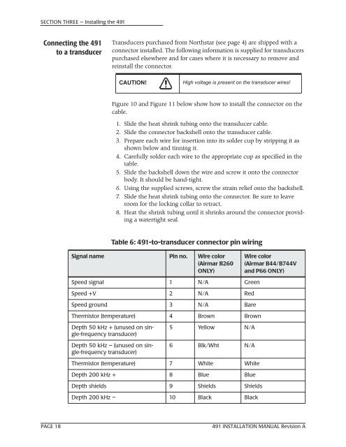
SECTION THREE — Installing the 491Connecting the 491to a transducerTransducers purchased from <strong>Northstar</strong> (see page 4) are shipped with aconnector installed. The following information is supplied for transducerspurchased elsewhere and for cases where it is necessary to remove andreinstall the connector.CAUTION!High voltage is present on the transducer wires!Figure 10 and Figure 11 below show how to install the connector on thecable.1. Slide the heat shrink tubing onto the transducer cable.2. Slide the connector backshell onto the transducer cable.3. Prepare each wire for insertion into its solder cup by stripping it asshown below and tinning it.4. Carefully solder each wire to the appropriate cup as specified in thetable.5. Slide the backshell down the wire and screw it onto the connectorbody. It should be hand-tight.6. Using the supplied screws, screw the strain relief onto the backshell.7. Slide the heat shrink tubing onto the connector. Be sure to leaveroom for the locking collar to retract.8. Heat the shrink tubing until it shrinks around the connector providinga watertight seal.Table 6: 491-to-transducer connector pin wiringSignal name Pin no. Wire color(Airmar B260ONLY)Wire color(Airmar B44/B744Vand P66 ONLY)Speed signal 1 N/A GreenSpeed +V 2 N/A RedSpeed ground 3 N/A BareThermistor (temperature) 4 Brown BrownDepth 50 kHz + (unused on single-frequencytransducer)Depth 50 kHz – (unused on single-frequencytransducer)5 Yellow N/A6 Blk/Wht N/AThermistor (temperature) 7 White WhiteDepth 200 kHz + 8 Blue BlueDepth shields 9 Shields ShieldsDepth 200 kHz – 10 Black BlackPAGE 18491 INSTALLATION MANUAL Revision A