Ryan NYP NX211 - Macca's Vintage Aerodrome
Ryan NYP NX211 - Macca's Vintage Aerodrome
Ryan NYP NX211 - Macca's Vintage Aerodrome

You also want an ePaper? Increase the reach of your titles
YUMPU automatically turns print PDFs into web optimized ePapers that Google loves.
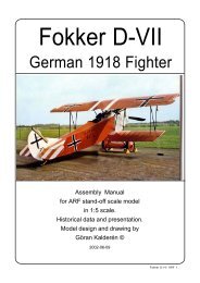
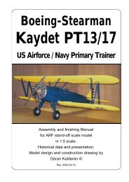
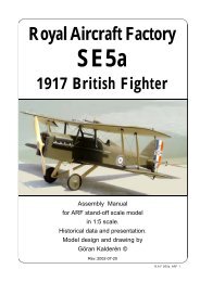
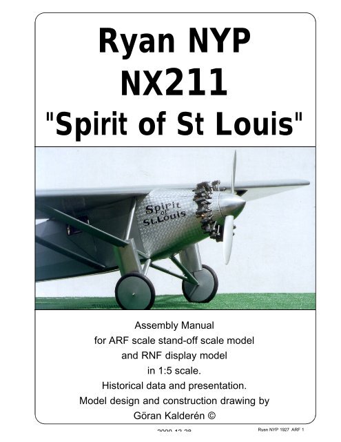
<strong>Ryan</strong> <strong>NYP</strong><br />
<strong>NX211</strong><br />
"Spirit of St Louis"<br />
Assembly Manual<br />
for ARF scale stand-off scale model<br />
and RNF display model<br />
in 1:5 scale.<br />
Historical data and presentation.<br />
Model design and construction drawing by<br />
Göran Kalderén ©<br />
2000-12-28<br />
<strong>Ryan</strong> <strong>NYP</strong> 1927 ARF 1
First Nonstop Solo Transatlantic Flight<br />
On May 21, 1927, the son of a Swedish<br />
immigrant, Charles A. Lindbergh completed the<br />
first solo non stop transatlantic flight in history.<br />
He flew his special built <strong>Ryan</strong> <strong>NYP</strong> “Spirit of<br />
St.Louis” 5,810 kilometers (3,610 miles) from<br />
Roosevelt Field on Long Island, New York to le<br />
Bourget airfield outside Paris, France in 33 hours<br />
and 30 minutes. With this achievement<br />
Lindbergh won the $25,000.- prize offered by the<br />
New York hotel owner Raymond Orteig to the<br />
first aviator to fly directly across the Atlantic from<br />
New York to Paris.. Charles Lindbergh became<br />
a world hero who would remain in the public eye<br />
for decades to follow.<br />
The aftermath of the flight was the<br />
“Lindbergh boom” in aviation. Aircraft industry<br />
stock rose in value and the interest in flying<br />
zoomed. Lindbergh’s subsequent tour in the<br />
“Spirit of St. Louis” demonstrated the airplane<br />
as a safe and reliable mode of transportation.<br />
Following the US tour he took the airplane on a<br />
goodwill tour to South and Central America. The<br />
flags of the countries that he visited were painted<br />
on the engine cowling.<br />
“Spirit of St. Louis” was named in honor<br />
of the supporters in St.Louis, who paid for the<br />
<strong>Ryan</strong> <strong>NYP</strong> 1927 ARF 2<br />
aircraft. “<strong>NYP</strong>” is the acronym for “New York-<br />
Paris”, the object of the flight.<br />
Design features<br />
The “Spirit of St. Louis” was designed by Donald<br />
Hall under the direct supervision of Charles<br />
Lindbergh. It is a highly modified version of a<br />
conventional <strong>Ryan</strong> M-2 strut-braced high wing<br />
monoplane, powered by a reliable Wright J-5C<br />
9 cylinder radial engine. Because the fuel tanks<br />
were located ahead of the cockpit for safety in<br />
case of an accident, the forward view was<br />
restricted or rather non-existent. Lindbergh could<br />
not see directly ahead but he could peek out<br />
through the open side windows or use a<br />
periscope mounted in his forward field of vision.<br />
Development<br />
<strong>NYP</strong> was an extensively modified M-2. The<br />
aircraft first flew on April 28, 1927. Between May<br />
10 and May 12 Lindbergh flew the plane from<br />
San Diego to New York in 21 hours and 40<br />
minutes, setting a new transcontinental record.<br />
The aircraft made its last flight on April 30, 1928<br />
when it arrived at the National Air and Space<br />
Museum in Washington DC, where it still resides<br />
today.<br />
Data<br />
Wingspan: 14 m (46 ft.)<br />
Length: 8 m (27 ft 8 in)<br />
Height: 3 m ( 9 ft 10 in)<br />
Wing area: 29,7 sq.m<br />
Weight gross: 2,330 kg (5,135 lb)<br />
Weight empty: 975 kg (2,150 lb)<br />
Engine: Wright Whirwind J-5C, 223hp<br />
Max. speed: 210 km/h<br />
Cruise speed: 180 km/h<br />
Ceiling: 5000 m<br />
Range: 6600 km<br />
Manufacturer: <strong>Ryan</strong> Airlines Co. San Diego,CA.<br />
Crew: 1
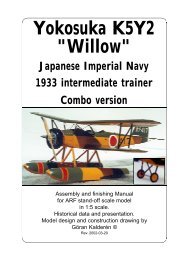
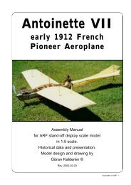
The original "Spirit of St. Louis" aircraft in the National<br />
Air & Space Museum in Waschington DC.<br />
<strong>Ryan</strong> <strong>NYP</strong> 1927 ARF 3
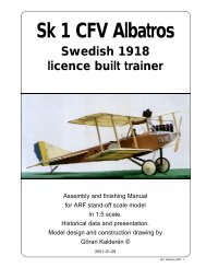
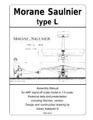
A replica built in France and now residing in the EAA Museum in Oskosh, U.S.A.<br />
<strong>Ryan</strong> <strong>NYP</strong> 1927 ARF 4
<strong>Ryan</strong> <strong>NYP</strong> 1927 ARF 5
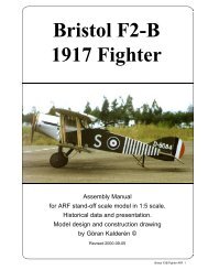
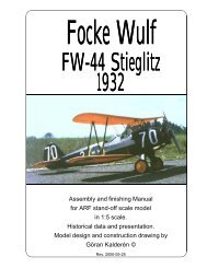
The Model<br />
I have chosen the scale 1:5, as it gives a reasonable<br />
big airplane but small enough to handle in a car,<br />
easy to assemble at the airfield and above all, is<br />
relatively forgiving to fly.<br />
The airplane comes with the tailskid attached and<br />
it remains only to attach the landing gear, the<br />
stabilizer in place and attach the fin and the rudder,<br />
control wires to the rudder and elevator horns. The<br />
stabilizer is supported by struts as by the full scale<br />
prototype. The elevator and rudder are actuated<br />
with pull-pull wires, which is scale and very reliable.<br />
The wires are attached directly to the rudder bar<br />
and the elevator control column.<br />
The wing halves are joined together with 5 mm<br />
spring steel rods in holes located in the wing root.<br />
The whole wing is placed on top of the fuselage<br />
and bolted to the frame with 4 Allen bolts. The wing<br />
struts are functional and are attached to the wings<br />
and fuselage (landing gear) with 3 mm screws and<br />
lock nuts.<br />
Specification<br />
Wingspan: 2800 mm 112"<br />
Length: 1600 mm 64"<br />
Wing surface: 119 dm² 1500 sq”<br />
Wing loading: 60 gm/dm² 16.2 oz/sq’<br />
Weight: 7200 gm 15 lb. 9oz.<br />
Engine: .60/.80 2-stroke or .90/1.20 4stroke<br />
For display version disregard sections marked<br />
with *<br />
*Engine installation<br />
The engine is installed upright in the plywood engine<br />
bearers. The cut-out is made for a 1..20 4-stroke<br />
engine. We used a Saito 1.20 engine in our<br />
prototype. A right thrust of 2-3° is recommended<br />
to compensate for the torque. We flew our<br />
prototype with 1° right thrust with additional rudder<br />
correction at full speed. In full size manner you<br />
can add side deflection on the fin instead of engine<br />
thrust deflection.<br />
Rudder and<br />
elevator servo<br />
linkages<br />
Elevator servo<br />
linkage<br />
Rudder cables<br />
<strong>Ryan</strong> <strong>NYP</strong> 1927 ARF 6<br />
Rudder<br />
servo<br />
linkage<br />
Remove the center upright dummy engine cylinder<br />
and parts of the crankcase. You will have to enlarge<br />
the openings in the aluminum covering plates<br />
depending on what engine you are installing.<br />
Where wood is removed, smoothen the surfaces<br />
and coat the whole interior with fuel proof paint.<br />
Lead the throttle cable to the servo through a hole<br />
in the firewall and connect the fuel tube from your<br />
tank to the carburettor.<br />
The tank is placed on the engine bearer board in<br />
the compartment behind the engine. This brings<br />
the tank level with the carburettor.<br />
*Special order version with vertical firewall<br />
Should you wish to install a radial engine like the<br />
Technopower 9 cylinder, 1/5th scale, here are the<br />
essential measurments for this installation.<br />
Dummy engine diameter 235 mm / 9.3”<br />
Firewall diameter 165 mm / 6.5”<br />
Spinner backplate 115 mm / 4.5”<br />
Distance firewall to spinner 75 mm / 3”<br />
*Radio/servo installation<br />
The receiver and battery are located on the upper<br />
tray behind the fire wall above the tank.<br />
The servos for rudder, elevator and throttle are<br />
affixed in the servo tray with special screws and<br />
Location of tank and<br />
throttle servo in<br />
fuselage<br />
Location<br />
of<br />
tank<br />
Rudder<br />
and elevator<br />
servos<br />
Location of<br />
Elevator<br />
cables
grommets. The ailreon servos (2) are located in<br />
the wing root of the wings.<br />
Rudder and elevator surfaces are controlled with<br />
cables from the rudderbar and the control column.<br />
Fuselage<br />
The fuselage is completely built up. It is complete<br />
with pulleys and all control wires attached. The<br />
stabilizer and fin must be attached to the fuselage<br />
and the wing appropriately affixed to the fuselage.<br />
Landing gear<br />
The landing gear has to be attached to the fuselage<br />
at the 6 attachment pionts using 3 mm screws<br />
and locknuts.<br />
1. First install the support angle at the side of the<br />
fuselage with 3 mm screws and locknuts. The open<br />
"fork" should be directed downward.<br />
2. Install the landing gear legs in the brackets in<br />
the lower part of the fuselage with 3 mm screws<br />
and locknuts.<br />
3. Connect the landing gear with the angular<br />
support with 3 mm screws and locknuts. Make<br />
sure that the longer rod of the oleo strut connects<br />
with the landing gear leg. Tighten the nuts enough<br />
to let the landing gear and the oleo strut move freely.<br />
4. Replace the aluminum cover and secure with<br />
#2 x 1/4" screws. See detail sketch for reference.<br />
The oleo struts are functional and the rubber band<br />
should be replaced when worn out.We have<br />
Main<br />
landing gear<br />
oleo strut<br />
support<br />
Rear landing<br />
gear leg<br />
Front landing<br />
gear leg<br />
Landing gear and wing strut support<br />
The oleo strut is first attached to the upper landing gear support.<br />
The aluminum cover plate is then pushed up from the bottom. Secure the cover plate with #2<br />
sheet metal screws. Then attach the lower end of the oleo strut to the landing gear shaft. For<br />
the entire landing gear assembly use 3 mm screws and lock nuts<br />
Rear wing strut<br />
Front wing strut<br />
Oleo strut with<br />
attachment pegs<br />
for bungee rubber<br />
Wheel<br />
collar<br />
Balsa strut<br />
fairing<br />
Front landing<br />
gear leg<br />
Oleo strut cover plate<br />
Landing gear and<br />
front wing strut support<br />
Landing gear and front<br />
wing strut support bracing.<br />
Same bolt as strut<br />
attachmentpoint<br />
Oleo strut with<br />
attachment pegs<br />
for bungee rubber<br />
Wing struts are made of flat<br />
steel faired with balsa. End<br />
fittings are heavy duty brass.<br />
The struts are attached to the<br />
fuselage and the wings with 3<br />
mm screws and locknuts.<br />
<strong>Ryan</strong> <strong>NYP</strong> 1927 ARF 7
installed a fresh set of rubber bands before<br />
shipment.<br />
Covered wooden wheels with tires are supplied.<br />
Spoked wheels are optional and available as extra<br />
parts. Secure the wheel collars with the 3 mm Allen<br />
set screws such that the wheels can turn freely<br />
and use Locktite or similar to secure the wheel<br />
collars.<br />
Stabilizer / elevator<br />
The stabilizer is attached to the fuselage with 3<br />
nylon screws. The stabilizer is secured with 3 preadjusted<br />
struts, attached with #2 screws to the<br />
fuselage.<br />
Attach the elevator wires from the elevator servo<br />
arm to the elevator horn. The elevator wires exit<br />
through holes in the rear of the fuselage and the<br />
upper wires pass through the stabilizer. Note that<br />
the wires are crossed in the fuselage so that the<br />
lower wire at the control column attaches to the<br />
upper horn on the elevator. Elevator deflection<br />
should be 20° up and down.<br />
Fin / rudder<br />
The fin and rudder with hinges is pushed in to the<br />
supporting tube in the fuselage. It is locked with 1<br />
#2 screw into the outer tube. The only remaining<br />
thing is to attach the rudder wires to the rudder.<br />
<strong>Ryan</strong> <strong>NYP</strong> 1927 ARF 8<br />
Hinge<br />
pins<br />
The rudder wires exit through holes in the rear of<br />
the fuselage. Rudder deflection should be 30° left<br />
and right.<br />
Wings<br />
The wing halves are joined together with 5 mm<br />
spring steel rods. The two aileron servos are<br />
installed in the servo mounts in he underside of<br />
the wings in the cabin area and connected to the<br />
push-pull aileron bellcrank. Pull-pull wires lead out<br />
to the ailerons via pulleys in front of the ailerons<br />
(scale function). Check the throw and function by<br />
temporarily connecting the servos to the radio. The<br />
complete wing is now placed on top of the fuselage<br />
with the window in the center. Four 5 mm Allen<br />
bolts secure the wing to the fuselage.<br />
Now the wing struts are installed with 3<br />
mm screws and locking nuts. The wingstruts are<br />
functional and has to be checked for security.<br />
Access to the inside of the cabin is through the<br />
door and the port side window. No clear panels<br />
were installed in the side windows of the original<br />
aircraft.<br />
*Finishing<br />
The model is covered with Solartex aluminum and<br />
all markings are painted with Dutch Boy black<br />
enamel.<br />
Installation of fin, rudder, stabilizer and elevator<br />
Fin front<br />
support bracket<br />
Screw for<br />
locking fin post<br />
to fuselage<br />
Elevator<br />
cables<br />
Stabilizer attachment<br />
screws ( 3 pcs nylon)
Aileron<br />
cables<br />
Aileron<br />
cables<br />
Aileron servo linkage<br />
Aileron<br />
servo Servo to<br />
bellcrank<br />
link<br />
Aileron<br />
bellcrank<br />
We suggest that you paint all wooden<br />
surfaces in the engine bay with one coat of clear<br />
fuel-proofing. Also on the areas where you have<br />
removed parts of the dummy engine to fit the flying<br />
engine in place.<br />
*Dummy engine<br />
A dummy of the Wright J-5, 9 cylinder<br />
engine is is supplied and has to be removed and<br />
remodeled to fit with your engine for flying. You can<br />
attach the dummy engine to the engine mount after<br />
removing one cylinder in lieu of the real engine.<br />
You may also have to make a cut-out in the upper<br />
aluminum nose panel. It is recommended to let<br />
the exhaust out via a flexible header end exit<br />
through the lowel nose cowl panel. There is plenty<br />
of room for the silencer inside the cowling. The<br />
above refers to the installation of a 1.20 4-stroke<br />
engine. We installed a Saito engine which has<br />
rocker covers closely resembling the Wright J-5.<br />
Scale propeller<br />
A finished scale propeller with spinner and spinner<br />
mounting plate is supplied. The hole is drilled for<br />
6,5 mm propeller shaft and may have to be<br />
enlarged to fit your engine. The spinner is attached<br />
to the backplate with 4 #2 screws. This propeller<br />
Aileron<br />
break<br />
pulleys<br />
Aileron<br />
horn<br />
Location of<br />
wing<br />
mounting<br />
bolts<br />
Aileron servo<br />
installation<br />
Aileron servo and<br />
aileron bellcrank<br />
seen from the top<br />
of the wing<br />
is not intended for flying. You can replace the<br />
propeller with one suitable for your engine. The<br />
attachment of the spinner cone with the #2 screws<br />
will however be subject to adding lockwashers to<br />
prevent the screws from loosening. Best is to<br />
acquire a 4½" aluminum spinner with central<br />
attachment screw for flying.<br />
*Balancing<br />
The airplane should balance at a point in the range<br />
of 9 -11cm (3.6"-4.4") wich is equal to 20 - 25% of<br />
the wing cord from the leading edge. Move the<br />
battery or add weight if required. A setting further<br />
forward will make the aircraft "groovy".<br />
Pitot tube and Windgenerator<br />
For transport reaseons both the long pitot tube and<br />
the windgeneratoror vane are separated from the<br />
model and packed separately. The pitot tube fits<br />
on the underside of the left wing just outside the<br />
wingstruts. Push the assembly gently but firmly<br />
into the 2 holes in the wing. The windgenerator<br />
vane is pushed into the hole on the top of the<br />
fuselage. Two ballbearings will enable the free<br />
turning of the vane. Friction will hold the vane axle<br />
in place.<br />
*Flying<br />
Make sure that you have set the elevator throw as<br />
recommended. Check also that the wings are level<br />
and have the proper wash out.<br />
Take off with this airplane is straight into the wind<br />
only. Don’t try to pull it of the ground. Let it lift off<br />
gently. Make the turns with coordinated rudder/<br />
elevator and aileron. It is not a pattern airplane!<br />
Remember that this airplane was built for a specific<br />
purpose; with a very high payload of fuel to cross<br />
the Atlantic Ocean from New York to Paris.<br />
The stabilizer area is relatively small but the<br />
moment arm long. Keep the speed up when you<br />
come in for landing. Enjoy cruising in the blue sky<br />
and feel the thrill of the imaginative re-enacting of<br />
the acomplishment of a successful early aviator.<br />
Happy and safe landings!<br />
<strong>Ryan</strong> <strong>NYP</strong> 1927 ARF 9
The left side<br />
landing gear<br />
with the<br />
streamlined<br />
covering removed<br />
The wing is attached with 4 Allen bolts. The<br />
window on top of the cockpit is an intergral<br />
part of the fuselage.<br />
<strong>Ryan</strong> <strong>NYP</strong> 1927 ARF 10<br />
The <strong>Ryan</strong> <strong>NYP</strong> before covering, painting and finishing<br />
The wing<br />
struts are<br />
functional<br />
Bungee<br />
rubber<br />
bands<br />
The <strong>Ryan</strong> <strong>NYP</strong> is constructed closely to<br />
the principles of the full size aircraft. The landing<br />
gear is fully functional with rubber bungee bands<br />
as chock absorber. The wing struts are functional<br />
and consist of steel straps, faired with balsa as<br />
on the full size original.<br />
The landing gear is constructed of heavy<br />
duty 5 mm steel spring steel wire to withstand<br />
the hardships of a not so good landings.<br />
The ailerons are activated by pull-pull<br />
wires from a bellcrank in the wing root to the<br />
aileron horns. The servos (2) are coupled with a<br />
short links to these bellcranks. The rudder and<br />
the elevator are connected with pul-pull wires in<br />
scale fashion and the control column as well as<br />
the rudder bar are connected to the servos with<br />
short links with ball links in one end. This gives a<br />
very positive and smoth action. The throw can<br />
be increased or decreased according to taste.<br />
The ailerons can also be set for differential throw<br />
(more up than down movement), recommended<br />
for the average skilled pilot.<br />
The engine installation is straight forward<br />
and the required cut-outs have to be made on<br />
the aluminum cover plates to accomodate the<br />
flying engine. The spinner has aluminum<br />
backplate and can be used for flying. The scale<br />
propeller has to be replaced for flying.
The right side landing gear has the<br />
streamlined covering installed<br />
The engine for flying (Saito 1.20 4-stroke) blends<br />
very inconspiciously with the dummy<br />
Wright Cyclone J-5 engine. The<br />
spinner is scale with<br />
display propeller<br />
A generous wing area renders low wing loading<br />
<strong>Ryan</strong> <strong>NYP</strong> 1927 ARF 11
What is in the box:<br />
The ARF kit contains the parts shown in the picture.<br />
All the parts are covered and painted. All the rigging<br />
3<br />
9<br />
K&W<br />
4<br />
1. Fuselage with tail skid.<br />
2. Landing gear assembly<br />
3. Scale wheels<br />
Model<br />
Airplanes Inc.<br />
<strong>Ryan</strong> <strong>NYP</strong> 1927 ARF 12<br />
8<br />
1<br />
2<br />
wires are supplied in the correct lengths and need<br />
only to be clipped to their positions.<br />
5 6<br />
4. Dummy engine with mount<br />
5. Scale propeller with spinner<br />
6. Fin / rudder<br />
7<br />
P.O.Box 1229, Cebu City Centrl. Postoffice<br />
Cebu City 6000, Philippines<br />
Visiting address:<br />
3343 Gun-Ob, Kinalumsan,<br />
Lapu-Lapu City 6015, PHILIPPINES<br />
Phone +63 32-340 7147, Cellular +63 917-3200 985<br />
Telefax +63 32-340 7131, E-mail: kwmairpl@gsilink.com<br />
8<br />
10<br />
7. Stabilizer / elevator<br />
8. Wing panels<br />
9. Wing struts<br />
10. Assembly manual