Bleriot XI 1909 - Macca's Vintage Aerodrome
Bleriot XI 1909 - Macca's Vintage Aerodrome
Bleriot XI 1909 - Macca's Vintage Aerodrome

Create successful ePaper yourself
Turn your PDF publications into a flip-book with our unique Google optimized e-Paper software.
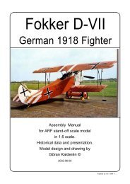
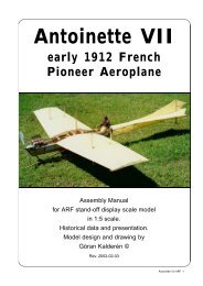
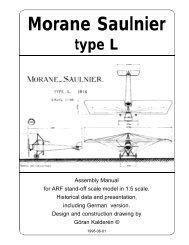
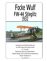
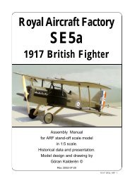
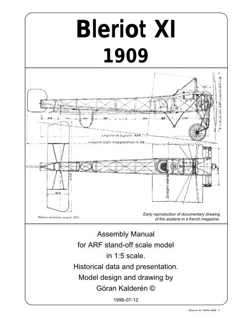
<strong>Bleriot</strong> <strong>XI</strong><br />
<strong>1909</strong><br />
Assembly Manual<br />
for ARF stand-off scale model<br />
in 1:5 scale.<br />
Historical data and presentation.<br />
Model design and drawing by<br />
Göran Kalderén ©<br />
1996-07-12<br />
Early reproduction of documentary drawing<br />
of the airplane in a french magazine.<br />
<strong>Bleriot</strong> <strong>XI</strong> <strong>1909</strong> ARF 1
The man and his aeroplane<br />
Louis <strong>Bleriot</strong> was the first aviator that in <strong>1909</strong><br />
successfully crossed the English Channel. The aeroplane<br />
was his model <strong>XI</strong> adapted for the flight, with<br />
an extra fuel tank mounted aft of the cockpit and the<br />
tail gear locked and braced in fixed position. The<br />
engine was an Anzani 3-cylinder "fan-type", aircooled<br />
with a rating of 28 hp. The plane was slightly<br />
underpowered and the flight in the early morning<br />
hours was executed sometimes only a few feet above<br />
the wet surface.<br />
This aeroplane became very popular all over<br />
Europe and was used by flying schools for basic training.<br />
More powerful engines were introduced and at<br />
the time of the outbreak of the hostilities 1914 one<br />
model was equipped with a Gnome Monsoupape 50<br />
hp rotary engine. The centre of thrust-line was then<br />
moved up to the centre of the fire wall.<br />
As to the tail gear this was sometimes simplified to<br />
two crossed bows of bent rattan appropriately fastened<br />
to the rear fuselage. The elevator was first<br />
fitted as the outer sections of the stabilizer but on<br />
Svensk Flyghistorisk Tidskrift<br />
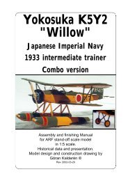
This photo shows <strong>Bleriot</strong> <strong>XI</strong> in the version 1912,<br />
registered S-12, with enlarged rudder planform,<br />
stabilizer with elevator along the rear edge and a<br />
Gnome rotary engine of 50 hp.<br />
This photo shows <strong>Bleriot</strong> <strong>XI</strong> in two versions. To<br />
the left the original with tail wheel, outer elevator<br />
panels and a 3-cyl Anzani 28 hp engine. To the<br />
right, the 1912 model with enlarged rudder planform,<br />
stabilizer with elevator along the rear edge<br />
and a Gnome rotary engine of 50 hp. Note also<br />
the substitution of the stearable tailwheel with two<br />
<strong>Bleriot</strong> <strong>XI</strong> <strong>1909</strong> ARF 2<br />
later models as a separate stabilizer and elevator<br />
along the rear edge of the former. The planform was<br />
also altered.<br />
The wings had fixed front spar and the rear<br />
spars attached with a joint to the fuselage. The wings<br />
were rigged with 2,5 ° dihedral measured from the<br />
wing root. Wing warping was executed via a "double<br />
cloche" the wires from the upper "cloche" were led<br />
through pulleys in the lover wire pylon out to the rear<br />
spar and the under side of the wing. The control was<br />
with a fixed wheel and could be moved forward - aft<br />
and left - right. The upper warping wires were run<br />
from the same positions on the upper side of the<br />
wings freely via pulleys on the upper wing support<br />
pylon.<br />
Elevator wires were run via guide pulley straight aft<br />
to the elevator horn, located in the centre line of the<br />
fuselage at the elevator main spar. Rudder control<br />
wires from the rudder bar to the rudder horn. The<br />
pilot was seated in a comfortable chair in the open<br />
cockpit frame and he had on his left side a throttle<br />
regulator and a magneto switch.<br />
At the beginning of the war Louis<br />
<strong>Bleriot</strong> joined forces with the well<br />
known S.P.A.D airplane company<br />
and many of his designs were notable<br />
developments of fighting aircrafts.<br />
A recent stamp from<br />
USA celebrating pioneer pilots<br />
Svensk Flyghistorisk Tidskrift<br />
crossed rattan bows. The latter model has also a<br />
turtle deck from the engine cowl to the cockpit.<br />
The upper winh support pylon is also reduced to<br />
a single inverted V. These aeroplanes were<br />
registreded in Sweden with numbers S-14 and<br />
S-15 and owned by baron Carl Cederström. Sold<br />
to the Swedish Army Airforce in 1913.
A<br />
A<br />
B C<br />
B<br />
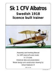
Control column<br />
Typical airfoil<br />
This 3-view depicts the <strong>Bleriot</strong> <strong>XI</strong> as it was<br />
equipped for the crossing of the English<br />
Channel. The construction drawing shows<br />
alternative stabilizer, rudder and tail skid<br />
C<br />
Control wires<br />
D<br />
D<br />
E<br />
E<br />
C - C<br />
A - A<br />
E - E<br />
B - B<br />
D - D<br />
<strong>Bleriot</strong> <strong>XI</strong> <strong>1909</strong><br />
assemblies as well as installation of Gnome 50<br />
hp rotary engine, cowl and turtle decking from<br />
engine to cockpit.<br />
<strong>Bleriot</strong> <strong>XI</strong> <strong>1909</strong> ARF 3
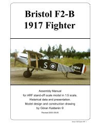
The photo above shows a <strong>Bleriot</strong> <strong>XI</strong> recently<br />
restored and flown by Michael Carlsson in Sweden.<br />
The tail skid is of later design as developed<br />
by Enoch Thulin on his licence built <strong>Bleriot</strong> <strong>XI</strong>.<br />
Also stabilizer has the later planform with ele-<br />
<strong>Bleriot</strong> <strong>XI</strong> <strong>1909</strong> ARF 4<br />
vator along the trailing edge. Engine is Thuli A-<br />
1 that develops 65 hp. Note also the turtle deck<br />
and the engine cowl.<br />
The 3-view below shows the licence built Thulin<br />
A (<strong>Bleriot</strong> <strong>XI</strong> bis).<br />
Thulin A<br />
(modified, licence built<br />
<strong>Bleriot</strong> <strong>XI</strong>)<br />
Ikaros<br />
Svensk Flyghistorisk Tidskrift
The photo above shows <strong>Bleriot</strong> <strong>XI</strong> owned and flown by the legendary baron Carl Cederström, here<br />
at Malmslätt in Sweden 1911.<br />
Below is the model in 1:5 scale. Kit plane is supplied with spoked wire wheels. The "Louis <strong>Bleriot</strong>"<br />
pilot figure is not included.<br />
The Model<br />
I have chosen the scale 1:5, as it gives a<br />
reasonable big airplane but small enough to handle in a<br />
car, easy to assemble at the airfield and above all, is<br />
relatively forgiving to fly. The model can be converted to<br />
the "Channel crosser" but we have chosen to build the<br />
somewhat later and impoved version.<br />
As you can see from the documentation the<br />
variations of the Bleeriot <strong>XI</strong> are numerous and your choice<br />
can be any one of the depicted aircrafts.<br />
The airplane comes with the landing gear<br />
attached and it remains only to screw the stabilizer in<br />
place and attach the and the rudder, control wires to the<br />
rudder and elevator horns. The wings are pushed into<br />
the fuselage in holes located on the sides and the wing<br />
supporting wires attached with the kwick links<br />
"turmbuckles. It may be necessary to adjust the tension<br />
of the wires.<br />
Specification<br />
Wingspan: 1602 mm 63,2 inches<br />
Length: 1366 mm 53,9 inches<br />
Stabilizor span: 667 mm 26,7 inches<br />
Wing incidence: 4 °<br />
Stab. incidence: 1 °<br />
Wing surface: 52 dm² 74 sq"<br />
Wing loading: 61 gm/dm² 19 oz/sq'<br />
Weight: 3200 gm 7 lb<br />
Engine: 40/60 2-stroke or 60/80 4-stroke<br />
Engine installation<br />
The engine is installed with the engine mount<br />
attached. Upright or slanted as you desire. Drill holes in<br />
the firewall to suit your engine and use 5 mm. screws<br />
and blind nuts as supplied. Lead the throttle cable to<br />
the servo through a hole in the firewall and connect the<br />
fuel tube from your tank to the carburator.<br />
Radio/servo installation<br />
The receiver and battery are located on the upper<br />
tray behind the fire wall alongside the tank.<br />
<strong>Bleriot</strong> <strong>XI</strong> <strong>1909</strong> ARF 5<br />
Ikaros
<strong>Bleriot</strong> <strong>XI</strong> <strong>1909</strong> ARF 6<br />
Rudder wires<br />
Elevator wires<br />
Upper warping<br />
wires<br />
Lower warping<br />
wires<br />
The location of the rigging wires.<br />
The servos for rudder, elevator and trottle are<br />
affixed in the servo tray with special screws and<br />
grommets. The wingwarping servo is affixed to the<br />
bracket below the rear wing tube fitting.<br />
All rudder surfaces are controlled with pull-pull<br />
wires, which is scale and very reliable. The wires are<br />
attached directly to the servo arms.<br />
Fuselage<br />
The fuselage is completely built up. This unit is<br />
complete with wheels and all rigging wires attached.<br />
The stabilizer must be attached to the fuselage and the<br />
wing appropriately affixed to the fuselage. The fire wall<br />
shoul get engine mounts affixed with bolts through the<br />
fire wall.<br />
If you have selected the ARF version you now have to<br />
attend to the finish. The allready covered model leaves<br />
only insignias and markings to be applied.<br />
Front landing<br />
(upper) wires<br />
Front flying<br />
(lower) wires<br />
Front flying<br />
(lower) wires are<br />
attached to the lower<br />
landing gear bar<br />
Rudder<br />
The rudder with hinges is pushed in to the<br />
fuselage and the hinges should be secured in position.<br />
The only remaining thing is to attach the rudder wires to<br />
the rudder.<br />
Stabilizor / elevator<br />
The stabilizer is attached to the fuselage at the<br />
underside of the fuselage using supplied screws through<br />
the stabilizer into the holes with blind nuts attached on<br />
the inside.<br />
Aluminium stabilizer support struts supplied,<br />
are fixed permanently to the fuselage and the stabilizor<br />
with sheet metal screws.<br />
Attach the elevator wires from the elevator servo<br />
arm to the elevator horn. Note that the wires are crossed<br />
so that the lower wire at the servo attaches to th upper<br />
horn on the elevator.<br />
The model has detailed reproduction of the empennage and the "tail skid" is made of rattan.
Model of <strong>Bleriot</strong> <strong>XI</strong> at a scale meet in Sweden. Builder and pilot: Lennart Waltersson<br />
Wings<br />
The wings are pushed into the holes in the<br />
fuselage. Start with attaching the upper front "landing"<br />
wires to the fittings in the wings.<br />
Next step is to attach the lower front "flying" wires to the<br />
fittings in the underside of the wings.<br />
Now add the upper wingwarping wires to the rear fittings<br />
on the upper side if the wings.<br />
Finally attach the warping actuating wires from the servo<br />
arm via the lower pulley out to the rear lower side fittings.<br />
When moving the servo arm the wing should now "warp".<br />
A deflection of ½" up and down at the wing tip is<br />
recomended. Make sure that the warping correspond<br />
to what you expect from ailerons on a conventional<br />
model.<br />
Rigging<br />
We will run over this step in condensed form<br />
once again. Start with the front upper wires. Attach the<br />
wires to the pylon pemanently. Clip the kwick-link<br />
"turnbuckle" to the eylet in the wings. Leave the kwivklink<br />
threaded half way on the screw. Insert the wire,<br />
stretch so that the wing tip gets the required dihedral<br />
2½° or 38 mm measured at the wing tip, and lock in<br />
position. Fine adjustments can be made later on the<br />
"turnbuckle". Proceed with the lower front wires in the<br />
same fashion. The wing is now locked in the proper<br />
position.<br />
Add the upper warping wires by attaching the<br />
kwick-links in the same manner as before. Starting on<br />
the outer rigging wire, fix it to the "turnbuckle", route it<br />
through the pulley in the rear upper pylon and then stretch<br />
it and fix it to the opposite wing panel. Make sure that<br />
you get the desired wash out at this moment. Proceed<br />
in the same manner with the inner upper warping wire,<br />
The lower warping wires are attached in much<br />
the same manner with the only difference that you start<br />
at the servo arm in the fuselage and the wire is routed<br />
via the pulley to the wing panel fixing point. Note that<br />
the wires are crossed from the pulley to the servo.<br />
The rudder an elevator wires ar installed in the<br />
same fashion starting at the servo arms. The<br />
"turnbuckles" ar located at the elevator and rudder horns.<br />
Route the wires straight to the respective ponts on the<br />
rudder and elevator horns.<br />
Finishing<br />
We suggest that you paint all wooden surfaces<br />
with 2 -3 coats of clear fuel-proofing. The wings and the<br />
tail feathers could also be given a coat of the same for<br />
the weathered antique look. Shrinking airplane dope is<br />
not recommended as you need the flexibility in the wings<br />
to minimize the strain on the warping servo.<br />
Dummy engine<br />
A dummy of the Anzani 3 cylinder engine is supplied<br />
and has to be removed and replaced wiith your engine<br />
for flying.<br />
Scale propeller<br />
Supplied is the finished scale propeller with front<br />
mounting plate. The hole is drilled for 6 mm propellershaft<br />
and may have to be enlarged to fit your engine.<br />
Flying<br />
Make sure that you have set the elevator throw<br />
as recommended. Check also that the wings have proper<br />
dihedral and wash out. The airplane should balance<br />
at a point 25 - 30% of the wing cord from the leading<br />
edge. Add weight at the front if required.<br />
Take off with this airplane is straight into the<br />
wind only. Dont try to pull it of the ground. Let it lift off<br />
gently. Make the turns with wing warping and rudder/<br />
elevator. It is not a pattern plane! Enjoy cruising in the<br />
blue sky and feel the thrill of the early aviator.<br />
Happy and safe landings!<br />
<strong>Bleriot</strong> <strong>XI</strong> <strong>1909</strong> ARF 7
What is in the box:<br />
The ARF kit contains the parts shown in<br />
the picture below. All the rigging wires are<br />
6<br />
K&W<br />
Model<br />
Airplanes Inc.<br />
<strong>Bleriot</strong> <strong>XI</strong> <strong>1909</strong> ARF 8<br />
10<br />
3<br />
1. Fuselage with wing warping pylon and<br />
tail skid assy.<br />
2. Landing gear<br />
3. Spoked wheels<br />
4. Rudder<br />
5. Elevator<br />
8<br />
2<br />
1<br />
supplied in the correct lengths and need only<br />
to be clipped to their positions.<br />
5<br />
P.O.Box 1229, Cebu City Centrl. Postoffice<br />
Cebu City 6000, Philippines<br />
Visiting address:<br />
3343 Gun-Ob, Kinalumsan,<br />
Lapu-Lapu City 6015, PHILIPPINES<br />
Phone +63 32-340 7147, Cellular +63 917-3200 985<br />
Telefax +63 32-340 7131, E-mail: kwmairpl@gsilink.com<br />
7<br />
6. Scale propeller<br />
7. Left wing panel<br />
8. Right wing panel<br />
9. Wires, turnbuckles and hardware for<br />
assembly (not shown)<br />
10. Assembly manual with scale documentation<br />
4