

System Level Modeling and Optimization of the LTE Downlink
System Level Modeling and Optimization of the LTE Downlink
System Level Modeling and Optimization of the LTE Downlink
- No tags were found...

Create successful ePaper yourself
Turn your PDF publications into a flip-book with our unique Google optimized e-Paper software.
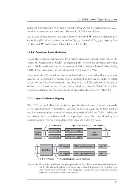
2. 3GPP Long Term EvolutionSince <strong>the</strong> CDD matrix cycles with a period <strong>of</strong> two, D k can be expressed as D k mod 2for <strong>the</strong> two transmit antenna case. For ν = 1, OLSM is not defined.In <strong>the</strong> case <strong>of</strong> four transmit antennas, instead <strong>of</strong> a fixed W matrix, a different precoderis applied after ν vectors, as well as D k mod 4 instead <strong>of</strong> D k mod 2 . AppropriateU, D k , <strong>and</strong> W matrices are defined for ν = 3, 4 in [39].2.2.1.3. Closed Loop Spatial MultiplexingUnless <strong>the</strong> feedback is invalidated by a rapidly changing channel, gains can be obtainedin comparison to OLSM by signaling <strong>the</strong> eNodeB an optimum precodingmatrix W in combination with <strong>the</strong> number <strong>of</strong> desired layers ν instead <strong>of</strong> employingCDD. Thus, expressing <strong>the</strong> output symbol vector y as y = Wx.In order to simplify signaling, instead <strong>of</strong> feedbacking <strong>the</strong> actual optimum precodermatrix [44], a precoder is chosen from a predefined codebook, <strong>the</strong> index <strong>of</strong> whichis sent to <strong>the</strong> eNodeB as feedback. For N TX = 2, <strong>the</strong> <strong>LTE</strong> codebook is comprised<strong>of</strong> four (ν = 1) <strong>and</strong> two (ν = 2) precoders, which are listed in Table 2.6. For fourtransmit antennas, <strong>the</strong> codebook spans 15 precoding choices for ν ∈ {1, 2, 3, 4}.2.2.2. Layer-to-Codeword MappingThe <strong>LTE</strong> st<strong>and</strong>ard allows for up to two parallel data streams, termed codewords,to be simultaneously transmitted. As seen in Section 2.2.1, up to four symbolscan be simultaneously transmitted when using ei<strong>the</strong>r OLSM or CLSM. While <strong>the</strong>precoding-related procedures work on a per-layer basis, <strong>the</strong> channel coding <strong>and</strong>channel quality reporting procedures work on a per-codeword basis.1 or 2 codewords layers <strong>of</strong> equal size: 1, 2, 3, or 4 layerschannelcodingscramblingscramblingmodulation mappermodulation mapperlayermapperRE mapperOFDM signal generationinsert CPprecodingRE mapperOFDM signal generationinsert CP1, 2, 3, or 4 layers antenna ports: 1, 2, or 4 antennasFigure 2.6: Modulation <strong>and</strong> layer mapping procedures [39]. The one or two codewords outputby <strong>the</strong> channel coding procedures are scrambled, mapped to complex symbols,distributed in ν layers (layer mapping), mapped to N TX transmit antennaports <strong>and</strong> converted to <strong>the</strong> time domain.17


