

System Level Modeling and Optimization of the LTE Downlink
System Level Modeling and Optimization of the LTE Downlink
System Level Modeling and Optimization of the LTE Downlink
- No tags were found...

Create successful ePaper yourself
Turn your PDF publications into a flip-book with our unique Google optimized e-Paper software.
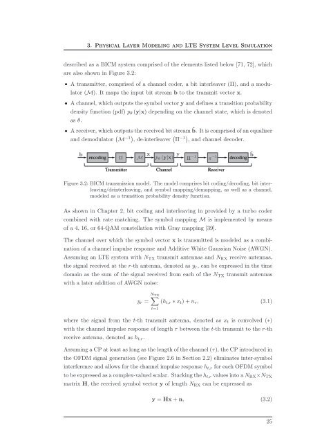
3. Physical Layer <strong>Modeling</strong> <strong>and</strong> <strong>LTE</strong> <strong>System</strong> <strong>Level</strong> Simulationdescribed as a BICM system comprised <strong>of</strong> <strong>the</strong> elements listed below [71, 72], whichare also shown in Figure 3.2:ˆ A transmitter, comprised <strong>of</strong> a channel coder, a bit interleaver (Π), <strong>and</strong> a modulator(M). It maps <strong>the</strong> input bit stream b to <strong>the</strong> transmit vector x.ˆ A channel, which outputs <strong>the</strong> symbol vector y <strong>and</strong> defines a transition probabilitydensity function (pdf) p θ (y|x) depending on <strong>the</strong> channel state, which is denotedas θ.ˆ A receiver, which outputs <strong>the</strong> received bit stream ˆb. It is comprised <strong>of</strong> an equalizer<strong>and</strong> demodulator ( M −1) , de-interleaver ( Π −1) , <strong>and</strong> channel decoder.encodingdecodingTransmitter Channel ReceiverFigure 3.2: BICM transmission model. The model comprises bit coding/decoding, bit interleaving/deinterleaving,<strong>and</strong> symbol mapping/demapping, as well as a channel,modeled as a transition probability density function.As shown in Chapter 2, bit coding <strong>and</strong> interleaving in provided by a turbo codercombined with rate matching. The symbol mapping M is implemented by means<strong>of</strong> a 4, 16, or 64-QAM constellation with Gray mapping [39].The channel over which <strong>the</strong> symbol vector x is transmitted is modeled as a combination<strong>of</strong> a channel impulse response <strong>and</strong> Additive White Gaussian Noise (AWGN).Assuming an <strong>LTE</strong> system with N TX transmit antennas <strong>and</strong> N RX receive antennas,<strong>the</strong> signal received at <strong>the</strong> r-th antenna, denoted as y r , can be expressed in <strong>the</strong> timedomain as <strong>the</strong> sum <strong>of</strong> <strong>the</strong> signal received from each <strong>of</strong> <strong>the</strong> N TX transmit antennaswith a later addition <strong>of</strong> AWGN noise:y r =N TX ∑t=1(h t,r ∗ x t ) + n r , (3.1)where <strong>the</strong> signal from <strong>the</strong> t-th transmit antenna, denoted as x t is convolved (∗)with <strong>the</strong> channel impulse response <strong>of</strong> length τ between <strong>the</strong> t-th transmit to <strong>the</strong> r-threceive antenna, denoted as h t,r .Assuming a CP at least as long as <strong>the</strong> length <strong>of</strong> <strong>the</strong> channel (τ), <strong>the</strong> CP introduced in<strong>the</strong> OFDM signal generation (see Figure 2.6 in Section 2.2) eliminates inter-symbolinterference <strong>and</strong> allows for <strong>the</strong> channel impulse response h t,r for each OFDM symbolto be expressed as a complex-valued scalar. Stacking <strong>the</strong> h t,r values into a N RX ×N TXmatrix H, <strong>the</strong> received symbol vector y <strong>of</strong> length N RX can be expressed asy = Hx + n, (3.2)25


