
Create successful ePaper yourself
Turn your PDF publications into a flip-book with our unique Google optimized e-Paper software.
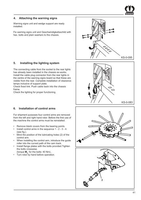
4. Attaching the warning signsWarning signs unit and wedge support are readyinstalled.Fix warning signs unit and Geschwindigkeitsschild withhex. bolts and plain washers to the chassis.KS-0-0955. Installing the lighting systemThe connecting cable from the socket to the rear lightshas already been installed in the chassis ex-works.Install the cable plug connector from the rear lights inthe centre of the warning signs board so that these arevisible from the rear. Complete installation of clearancelamps inclusive of support plate.Check fixed link. Push cable back into the chassisframe.Check the lighting for proper functioning.KS-0-0836. Installation of control armsFor shipment purposes four control arms are removedfrom the left and right hand rotor. Before the first use ofthe machine the control arms must be reinstalled.• Remove blank covers from the bearing points.• Install control arms in the sequence 1 - 2 - 3 - 4.(see fig.).• Mind the position of the lubricating holes (2) of thecontrol arm.• When installing the control arm, introduce the guideroller into the curved path of the cam track.• Install flange plates with the bolts provided.Tightenthe bolts crosswise.(torque M Afor the bolts: 40 Nm)..• Turn rotor by hand before operation.AB12344545241