- Page 1 and 2: XG-V10XUSERVICE MANUALSX0L5XG-V10XU
- Page 3 and 4: 12345678901234567890123456789012123
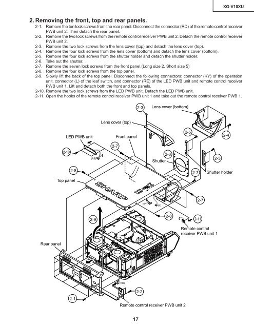
- Page 5 and 6: 12345678901234567890123456789012123
- Page 7 and 8: 12345678901234567890123456789012123
- Page 9 and 10: XG-V10XUProjectorSpeakersSide and R
- Page 11 and 12: XG-V10XUUsing the Remote Control as
- Page 13 and 14: XG-V10XUUse as a Laser PointerSlide
- Page 18 and 19: XG-V10XU3. Removing the reinforcing
- Page 20 and 21: XG-V10XU5. Removing the power/balla
- Page 22 and 23: XG-V10XULayout of the optical syste
- Page 24 and 25: XG-V10XUNotes :1 The eccentric cam
- Page 26 and 27: XG-V10XUReplacing the LCDsRemove th
- Page 28 and 29: XG-V10XU11M5 adjusting leverMirror
- Page 30 and 31: XG-V10XUNo. Adjusting point Adjusti
- Page 32 and 33: XG-V10XUNo. Adjusting point Adjusti
- Page 34 and 35: XG-V10XUNo. Adjusting point Adjusti
- Page 36 and 37: XG-V10XUNo. Adjusting point Adjusti
- Page 38 and 39: XG-V10XUProcess menu1ADOUTPUT1OUTPU
- Page 40 and 41: XG-V10XUPrecautions in servicing(1)
- Page 42 and 43: XG-V10XUTROUBLE SHOOTING T ABLE (Co
- Page 44 and 45: XG-V10XUTROUBLE SHOOTING T ABLE (Co
- Page 46 and 47: XG-V10XUTROUBLE SHOOTING T ABLE (Co
- Page 48 and 49: XG-V10XUTROUBLE SHOOTING T ABLE (Co
- Page 50 and 51: XG-V10XUTROUBLE SHOOTING T ABLE FOR
- Page 52 and 53: XG-V10XUTROUBLE SHOOTING T ABLE FOR
- Page 54 and 55: XG-V10XUTROUBLE SHOOTING T ABLE FOR
- Page 56 and 57: XG-V10XUTROUBLE SHOOTING T ABLE FOR
- Page 58 and 59: XG-V10XUTROUBLE SHOOTING T ABLE FOR
- Page 60 and 61: XG-V10XUTROUBLE SHOOTING T ABLE FOR
- Page 62 and 63: XG-V10XUCHASSIS LAYOUTHGFEDCBA12345
- Page 64 and 65: XG-V10XUBLOCK DIAGRAMHGFEDCBA123456
- Page 66 and 67:
XG-V10XUOVERALL WIRING DIAGRAMHGFED
- Page 68 and 69:
XG-V10XUDESCRIPTION OFSCHEMATIC DIA
- Page 70 and 71:
XG-V10XUË OUTPUT UNIT-1/9HGFEDCBA1
- Page 72 and 73:
XG-V10XUË OUTPUT UNIT-2/9HGFEDCBA1
- Page 74 and 75:
XG-V10XUË OUTPUT UNIT-3/9HGFEDCBA1
- Page 76 and 77:
XG-V10XUË OUTPUT UNIT-4/9HGFEDCBA1
- Page 78 and 79:
XG-V10XUË OUTPUT UNIT-5/9HGFEDCBA1
- Page 80 and 81:
XG-V10XUË OUTPUT UNIT-6/9HGFEDCBA1
- Page 82 and 83:
XG-V10XUË OUTPUT UNIT-7/9HGFEDCBA1
- Page 84 and 85:
XG-V10XUË OUTPUT UNIT-8/9HGFEDCBA1
- Page 86 and 87:
XG-V10XUË OUTPUT UNIT-9/9HGFEDCBA1
- Page 88 and 89:
XG-V10XUË OUTPUT SUB UNITHGFEDCBA1
- Page 90 and 91:
XG-V10XUË SIGNAL UNIT-1/5HGFEDCBA1
- Page 92 and 93:
XG-V10XUË SIGNAL UNIT-2/5HGFEDCBA1
- Page 94 and 95:
XG-V10XUË SIGNAL UNIT-3/5HGFEDCBA1
- Page 96 and 97:
XG-V10XUË SIGNAL UNIT-4/5HGFEDCBA1
- Page 98 and 99:
XG-V10XUË SIGNAL UNIT-5/5HGFEDCBA1
- Page 100 and 101:
XG-V10XUË LED UNITHGFEDCBA11223435
- Page 102 and 103:
XG-V10XUË R/C RECEIVER-2 UNITHGFED
- Page 104 and 105:
XG-V10XUË INPUT UNIT-1/3HGFEDCBA12
- Page 106 and 107:
XG-V10XUË INPUT UNIT-2/3HGFEDCBA12
- Page 108 and 109:
XG-V10XUË INPUT UNIT-3/3HGFEDCBA12
- Page 110 and 111:
XG-V10XUË POWER AND INLET UNITHGF(
- Page 112 and 113:
XG-V10XUË PC I/F UNIT-1/8HGFEDCBA1
- Page 114 and 115:
XG-V10XUË PC I/F UNIT-2/8HGFEDCBA1
- Page 116 and 117:
XG-V10XUË PC I/F UNIT-3/8HGFEDCBA1
- Page 118 and 119:
XG-V10XUË PC I/F UNIT-4/8HGFEDCBA1
- Page 120 and 121:
XG-V10XUË PC I/F UNIT-5/8HGFEDCBA1
- Page 122 and 123:
XG-V10XUË PC I/F UNIT-6/8HGFEDCBA1
- Page 124 and 125:
XG-V10XUË PC I/F UNIT-7/8HGFEDCBA1
- Page 126 and 127:
XG-V10XUË PC I/F UNIT-8/8HGFEDCBA1
- Page 128 and 129:
XG-V10XUPRINTED WIRING BOARD ASSEMB
- Page 130 and 131:
XG-V10XUHGFOutput Sub Unit (Wiring
- Page 132 and 133:
XG-V10XUHGFEDCBASignal Unit (Wiring
- Page 134 and 135:
XG-V10XUHGFEDCBAInput Unit (Wiring
- Page 136 and 137:
XG-V10XUHGFEDCBAPower Unit (Wiring
- Page 138 and 139:
XG-V10XUHGFEDCBAPC I/F Unit (Wiring
- Page 140 and 141:
XG-V10XUHGFEInlet Unit (Wiring Side
- Page 142 and 143:
XG-V10XURef. No. Part No. ★ Descr
- Page 144 and 145:
XG-V10XURef. No. Part No. ★ Descr
- Page 146 and 147:
XG-V10XURef. No. Part No. ★ Descr
- Page 148:
XG-V10XURef. No. Part No. ★ Descr
- Page 151 and 152:
XG-V10XURef. No. Part No. ★ Descr
- Page 153 and 154:
XG-V10XURef. No. Part No. ★ Descr
- Page 155 and 156:
XG-V10XURef. No. Part No. ★ Descr
- Page 157 and 158:
XG-V10XURef. No. Part No. ★ Descr
- Page 159 and 160:
XG-V10XURef. No. Part No. ★ Descr
- Page 161 and 162:
XG-V10XURef. No. Part No. ★ Descr
- Page 163 and 164:
XG-V10XURef. No. Part No. ★ Descr
- Page 165 and 166:
XG-V10XURef. No. Part No. ★ Descr
- Page 167 and 168:
XG-V10XURef. No. Part No. ★ Descr
- Page 169 and 170:
XG-V10XURef. No. Part No. ★ Descr
- Page 171 and 172:
XG-V10XURef. No. Part No. ★ Descr
- Page 173 and 174:
XG-V10XURef. No. Part No. ★ Descr
- Page 175 and 176:
XG-V10XURef. No. Part No. ★ Descr
- Page 177 and 178:
Ref. No. Part No. ★ Description C
- Page 179 and 180:
Ref. No. Part No. ★ Description C
- Page 181 and 182:
XG-V10XUPACKING OF THE SETRef. No.