3160 - Trace oxygen analyzer - Teledyne Analytical Instruments
3160 - Trace oxygen analyzer - Teledyne Analytical Instruments
3160 - Trace oxygen analyzer - Teledyne Analytical Instruments
- No tags were found...
You also want an ePaper? Increase the reach of your titles
YUMPU automatically turns print PDFs into web optimized ePapers that Google loves.
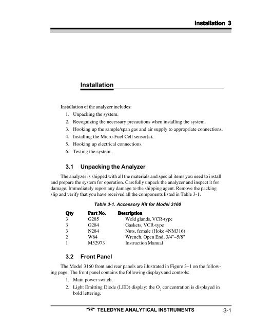
Installation 3InstallationInstallation of the <strong>analyzer</strong> includes:1. Unpacking the system.2. Recognizing the necessary precautions when installing the system.3. Hooking up the sample/span gas and air supply to appropriate connections.4. Installing the Micro-Fuel Cell sensor(s).5. Hooking up electrical connections.6. Testing the system.3.1 Unpacking the AnalyzerThe <strong>analyzer</strong> is shipped with all the materials and special items you need to installand prepare the system for operation. Carefully unpack the <strong>analyzer</strong> and inspect it fordamage. Immediately report any damage to the shipping agent. Remove the packingslip and verify that you have received all the components listed in Table 3-1.Table 3-1. Accessory Kit for Model <strong>3160</strong>QtyPart No.Description3 G285 Weld glands, VCR-type3 G284 Gaskets, VCR-type3 N284 Nuts, female (Hoke 4NM316)2 W64 Wrench, Open End, 3/4"–5/8"1 M52973 Instruction Manual3.2 Front PanelThe Model <strong>3160</strong> front and rear panels are illustrated in Figure 3–1 on the followingpage. The front panel contains the following displays and controls:1. Main power switch.2. Light Emitting Diode (LED) display: the O 2concentration is displayed inbold lettering.TELEDYNE ANALYTICAL INSTRUMENTS3-1


