Manual - Hawk Measurement Systems!
Manual - Hawk Measurement Systems!
Manual - Hawk Measurement Systems!

Create successful ePaper yourself
Turn your PDF publications into a flip-book with our unique Google optimized e-Paper software.
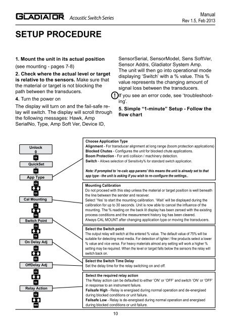
Acoustic Switch Series<strong>Manual</strong>Rev 1.5, Feb 2013Acoustic Switch Series<strong>Manual</strong>Rev 1.5, Feb 2013SETUP PROCEDURESETTING MAXIMUM RANGE1. Mount the unit in its actual position(see mounting - pages 7-8)2. Check where the actual level or targetis relative to the sensors. Make sure thatthe material or target is not blocking thepath between the transducers.!4. Turn the power onThe display will turn on and the fail-safe relaywill switch. The display will scroll throughthe following messages: <strong>Hawk</strong>, AmpSerialNo, Type, Amp Soft Ver, Device ID,Unlock0CALQuickSetCALApp TypeCALCALCal MountingCALCALSwitch PointCALCALOn Delay AdjCALCALOffDelay AdjCALCALRelay ActionCALRUN10SensorSerial, SensorModel, Sens SoftVer,Sensor Addrs, Gladiator System Amp.The unit will then go into operational modedisplaying ‘Switch’ with a % value. This %value represents the changing amount ofsignal loss between the transducers.If you see an error code, see ‘troubleshooting’.5. Simple “1-minute” Setup - Follow theflow chartChoose Application TypeAlignment - For transducer alignment at long range (boom protection applications)Blocked Chutes - Configures the unit for blocked chute applications.Boom Protection - For anti collision / machinery detection.Switch - Allows selection of Sensitivity% for standard switch application.Note: If prompted to ‘re-calc app params’ this means the unit is already set to thatapp type - the unit is asking if you wish to re-configure the settings..Mounting CalibrationDo not proceed with this step unless the material or target position is well beneaththe line between the sender and receiver.Select ‘Yes’ to start the mounting calibration. ‘Wait’ will be displayed during thecalibration for up to 30 seconds. Unit is now able to cancel the influence of themounting. The % reading on the back lit display has been zeroed with the existingprocess conditions and the measurement history log has been cleared.Always CAL MOUNT after changing application type or moving the transducers.Select the Switch pointThe output relay will switch at the entered % value. The default value of 75% will besuitable for detecting most media. For detection of lighter / fine products select a lower% value and vice versa. For heavy materials almost any setting will work a higher %setting may be required. When the level or target falls below the sensors the relay willswitch back on.Select the Switch Time DelaySet the delay time for the relay switching on and off.Select the required relay actionThe Relay action can be defaulted to either ‘ON’ or ‘OFF’ and switch ‘ON’ or ‘OFF’in response to an instrument failure.Failsafe High - Relay is energised during normal operation and de-energisedduring blocked conditions or unit failure.Failsafe Low - Relay is de-energised during normal operation and energisedduring blocked conditions or unit failure.After a calibration the unit has a high &fluctuating switch%Check the echo distance diagnostic(while the unit is RUNNING, press downarrow until the top line reads E: x.xx.If this value (distance) is double the approximatespace between sensors or greater youwill need to adjust the ‘empty distance’ torestrict the maximum range.The setting is called ‘Empty Dist’ in the mainmenu labelled ‘Advanced’.Press CAL toedit, then the arrow to adjust this distanceto 125% of the space between the sensors(example, if there is approximately 4.00mbetween the sensors adjust this value to5.00m).11