Manual - Hawk Measurement Systems!
Manual - Hawk Measurement Systems!
Manual - Hawk Measurement Systems!

Create successful ePaper yourself
Turn your PDF publications into a flip-book with our unique Google optimized e-Paper software.
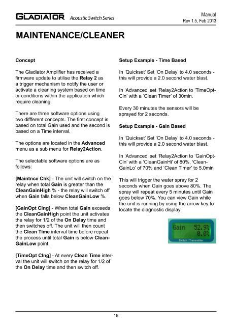
Acoustic Switch Series<strong>Manual</strong>Rev 1.5, Feb 2013Acoustic Switch Series<strong>Manual</strong>Rev 1.5, Feb 2013MAINTENANCE/CLEANERTROUBLESHOOTINGConceptThe Gladiator Amplifier has received afirmware update to utilise the Relay 2 asa trigger mechanism to notify the user oractivate a cleaning system based on timeor conditions within the application whichrequire cleaning.There are three software options usingtwo diffferent concepts. The first concept isbased on total Gain used and the second isbased on a Time interval.The options are located in the Advancedmenu as a sub menu for Relay2Action.The selectable software options are asfollows:[Maintnce Chk] - The unit will switch on therelay when total Gain is greater than theCleanGainHigh % - the relay will switch offwhen Gain falls below CleanGainLow %.[GainOpt Clng] - When total Gain exceedsthe CleanGainHigh point the unit activatesthe relay for 1/2 of the On Delay time andthen switches off. The unit will then countthe Clean Time interval time before repeatthe process until total Gain is below Clean-GainLow point.[TimeOpt Clng] - At every Clean Time intervalthe unit will switch on the relay for 1/2 ofthe On Delay time and then switch off.Setup Example - Time BasedIn ‘Quickset’ Set ‘On Delay’ to 4.0 seconds -this will provide a 2.0 second water blast.In ‘Advanced’ set ‘Relay2Action to ‘TimeOpt-Cln’ with a ‘Clean Timer’ of 30min.Every 30 minutes the sensors will besprayed for 2 seconds.Setup Example - Gain BasedIn ‘Quickset’ Set ‘On Delay’ to 4.0 seconds -this will provide a 2.0 second water blast.In ‘Advanced’ set ‘Relay2Action to ‘GainOpt-Cln’ with a ‘CleanGainHi’ of 80%, ‘Clean-GainLo’ of 70% and ‘Clean Timer’ to 5.0minThis will trigger the water spray for 2seconds when Gain goes above 80%. Thespray will repeat every 5 minutes until Gaingoes below 70%. You can view Gain whilethe unit is running by using the arrow key tolocate the diagnostic displayERROR CODESToo Many Transducers - This code can bedisplayed if both transducers are alreadycorrectly initialised when run the InitialiseTX program. Press and hold the RUNbutton to exit this code loop.Com Retry - Unit is attempting tocommunicate with a transducer.Failed - Unit has failed to communicate withboth transducers. Check amplifier & junctionbox wiring connections. Pull each wire toensure they are locked in correctly.Error No 01 - Amplifier cannotcommunicate with transducer 1.Error No 11 - Amplifier cannotcommunicate with transducer 2.Existing installation: For both error codes1 and 11 the first thing to check is theamplifier & junction box wiring connections,both <strong>Hawk</strong> and customer supplied ifapplicable. Pull each wire to ensure theyare locked in correctly. Check sensor fordamage.New installations: You may need tore-initialise the transducers. The reinitialisationsequence assigns eachan ID which the amplifier is looking tocommunicate with.The re-initialise program is in the ‘Advanced’Menu. While an error code is on the screenyou will need to push and firmly hold theCAL button to access the unlock screen.This may take 5-10 seconds.Error 02: Amplifier can talk to transducerbut transducer gives incorrect response.This can indicate a communicationdata corruption between Amplifier andTransducer. It can be a result of noise indata lines or one of data lines (blue or white)being open circuit.Error 03: A communications option inoutput adjustment has been selected (egProfibus, FF) but the module is not present,connected or responding.Error 04: Amplifier is programmed withincorrect software.Error 08: Incorrect transducer - ensureconnected transducer is Acoustic Switch(AS).POWER SUPPLYLCD / LEDs / Relays dimming or droppingout in non-blocked conditions.The GSASUS when powered by AC willoutput a DC voltage from the DC +/-terminals.You should read approx 16V stable from DC+/- while under AC power. If your AC poweris stable and the DC is outputting a lower orunstable value there is likely a problem withthe internal AC power supply. You can usea 24DC regulator and power the unit via DCterminals.High / Inconsistance switch % aftercalibrationSee ‘setting maximuim range’1819