Manual - Hawk Measurement Systems!
Manual - Hawk Measurement Systems!
Manual - Hawk Measurement Systems!

Create successful ePaper yourself
Turn your PDF publications into a flip-book with our unique Google optimized e-Paper software.
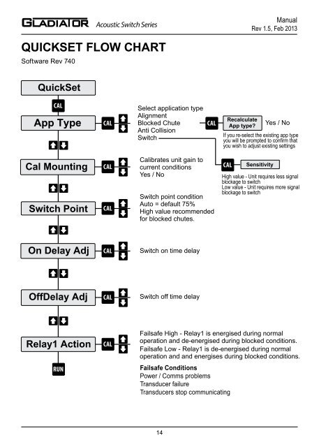
Acoustic Switch Series<strong>Manual</strong>Rev 1.5, Feb 2013Acoustic Switch Series<strong>Manual</strong>Rev 1.5, Feb 2013QUICKSET FLOW CHARTQUICKSET PARAMETERSSoftware Rev 740QuickSetCALApp TypeCal MountingSwitch PointOn Delay AdjOffDelay AdjRelay1 ActionRUNCALCALCALCALCALCALSelect application typeAlignmentBlocked ChuteAnti CollisionSwitchCalibrates unit gain tocurrent conditionsYes / NoSwitch point conditionAuto = default 75%High value recommendedfor blocked chutes.Switch on time delaySwitch off time delayCALRecalculateApp type?Yes / NoIf you re-select the existing app typeyou will be prompted to confirm thatyou wish to adjust existing settingsCALSensitivityHigh value - Unit requires less signalblockage to switchLow value - Unit requires more signalblockage to switchFailsafe High - Relay1 is energised during normaloperation and de-energised during blocked conditions.Failsafe Low - Relay1 is de-energised during normaloperation and and energises during blocked conditions.Failsafe ConditionsPower / Comms problemsTransducer failureTransducers stop communicatingApp TypeAlignment - For Aligning the unit at longrange (boom protection applications). Unitis set to 1.2V signal (~48% sw value). Movethe unit face to get the sw value readinglow (0% indicates perfect alignment at currentgain setting). Calibrate & re-select thismode and repeat till you cannot improve thealignment. This mode is only for alignment,not for an active process.Blocked Chute - Configures the unit forblocked chute applicationsBoom Protection - Sets the unit to BoomProtection mode. This can also be used formachinery or object detectionSwitch - For standard switch applicationswhere blocked chute or boom protectionis not appropriate. A high value will makethe unit more sensitive to switching andresponding to lighter materials. A low valuewill make the unit more resilliant and ignoredust / build up.Cal MountingDo not proceed with this step unless thematerial or target position is well beneth theline between the transducers.Select ‘Yes’ to start the mounting calibration.‘Wait’ will be displayed during the calibrationduring the procedure and the StatusA & B lights will flash while the unit is pulsing.The unit then performs a final check.The Cal Mounting process configures thesystem to the optimum settings to achievea 2.4V signal (signal in volts viewable in thediagnostics).Switch PointAuto: The output relay will switch on at displayed% value (default 75%) Auto settingswill be suitable for detecting most media.Adjusting the switch on % will automaticallyadjust the switch off %. For blocked chuteapplications a higher % switch on value isrecommend such as 90%.<strong>Manual</strong>: To adjust both switch point valuessee ‘Switch Mode’ in the ‘Advanced’ menu.On & Off Delay AdjustmentSet the time to be used for both switch onand switch off delays (default: 1 second).Relay1 ActionRelay1 can be set to Low or High.When the Relay is in high mode it is alwaysswitched on (EN) and will switch off (DEN)when there is a blocked chute condition orunit failure. High is recommended.When in Low mode the Relay will beswitched off (DEN) during normal operationand will switch on (EN) when there is ablocked chute condition or unit failure.1415