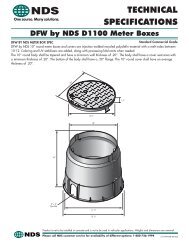
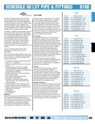
Installation Guide(Continued)PGJ, PGP ® and I-20 Ultra Rotary Sprinklers Nozzle Installation1. Insert the plastic key end of the <strong>Hunter</strong> wrench intothe lifting socket of the sprinkler and turn 90°. Pull theriser up to gain access to the nozzle socket.2. Using the hex key of the <strong>Hunter</strong> wrench, turn theradius adjustment screw counterclockwise to be sureit is not blocking the nozzle socket opening. If a nozzleis already installed, it can be removed by backing outthe adjustment screw and turning on the water, or bypulling outward on the nozzle “ears” with a pair ofneedle-nosed pliers.3. Slip the desired nozzle into the nozzle socket. Notethat the socket is angled up 25˚, and that the I-20Ultra nozzle has a fl at top. The “ears” should beadjusted so that the nozzle range screw threadsdirectly down between them. Then tighten the nozzlerange screw. The raised bump with an arrow on therubber cover will always indicate the location of thenozzle and direction of water fl ow when the sprinkleris retracted.4. Turn nozzle-retainer/radius-adjustment screwcounterclockwise to increase radius, clockwise todecrease radius.5. If larger radius is desired, install larger nozzle (thiswill also increase precipitation rate). If smallerradius is desired, install smaller nozzle (this will alsodecrease precipitation rate).I-25 Plus, I-40 Group and I-90 Rotary Sprinklers Nozzle InstallationWater Flow1. Insert the plastic key end of the <strong>Hunter</strong> wrench intothe lifting socket of the sprinkler and turn 90°. Pull theriser up to gain access to the nozzle socket.2. Using the <strong>Hunter</strong> wrench, loosen the nozzle-retainer/range-adjustment screw. If a nozzle is already installedin the sprinkler, it may be removed by briefl y turningon the water or by pulling outward on the nozzlewith a pair of needle-nosed pliers. Discard nozzle ifremoved with pliers.3. Slip the desired new nozzle into the nozzle socket. Notethat the socket is angled up 25°. Push all the way in.Tighten the nozzle-retainer/range-adjustment screw.4. Turn nozzle-retainer/radius-adjustment screwcounterclockwise to increase radius, clockwise todecrease radius.5. If larger radius is desired, install larger nozzle (thiswill also increase precipitation rate). If smallerradius is desired, install smaller nozzle (this will alsodecrease precipitation rate).I-60 Nozzle InstallationTools needed: T-handle tool part number 319100,riser service tool part number 279100, <strong>Hunter</strong> wrenchor 3 ⁄32" Allen.PreparationUnscrew the body cap from the body of the sprinkler.Remove the body cap. Using the key end of the <strong>Hunter</strong>wrench, pull up on the riser assembly to remove it fromthe body. Place the riser assembly’s lower end into thebase of riser service tool part number 279100. Pressthe tool’s metal bar down over the riser spring. Continuecompressing the spring until the bar enters the slots inthe tool’s base. Rotate the bar to engage with the tool’sbase, thereby holding the spring under tension.Nozzle Removal and ReplacementI-60-36S: The nozzle is retained in the nozzle housing bya setscrew. To remove the nozzle, back out the setscrewso that the nozzle will clear. Rotate the nozzle housing toplace the diffuser yoke at its lowest position in order toprovide clearance. Grasp a nozzle tab with pliers and pullto remove.I-60-ADS: The nozzle is retained in the nozzle housingby a setscrew. To remove the nozzle, fi rst slide the diffuserpins to the extreme left, from the viewer’s perspective,past the black stop post.All Models: Place the replacement nozzle in the housing.Press fi rmly to fully seat the nozzle so that it willclear the retaining setscrew. This can be accomplishedwith the T-handle tool’s open end. Run the setscrewdown to retain the nozzle, taking care not to run it downso far as to interfere with the nozzle stream. For I-60-ADSmodels, ensure the diffuser pins are placed back in linewith the nozzle.Visually check for proper assembly of nozzles and setscrews.Reverse the preparation procedure to reassemblethe unit.PGJ, PGP ® , I-20 Ultra, I-25 Plus, I-40 Group, I-60 and I-90 Rotary Sprinklers Pop-up InstallationPGJ, PGP, I-20 Ultra, I-25 Plus, I-40 Group, I-60 pop-upand I-90 sprinklers should be installed at grade asshown here. Manually rotate sprinkler nozzle from stopto stop to determine sprinkler orientation.112
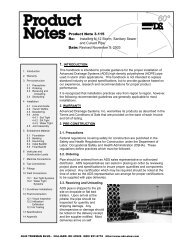
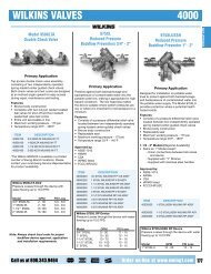
PGJ, PGP ® , I-20 Ultra, I-25 Plus, I-40 Group and I-90 Rotary Sprinklers Arc AdjustmentTo increase arc:1. Insert the plastic key end of the <strong>Hunter</strong> wrench intothe adjustment socket.2. While holding the nozzle turret at the right stop, turnthe wrench clockwise. Each 360˚ turn of the wrenchincreases arc 90˚ (45˚ for I-25 Plus and I-40 group).3. Wrench will stop turning or there will be a ratchetingnoise when adjusted to the maximum arc (360˚).4. Adjust to any arc between 40˚ and 360˚.To decrease arc:1. Insert the plastic key end of the <strong>Hunter</strong> wrench intothe adjustment socket.2. While holding the nozzle turret at the right stop,turn the wrench counterclockwise. Each 360˚ turnof the wrench decreases arc 90˚ (45˚ for I-25 Plus andI-40 group).3. Wrench will stop turning or there will be a ratchetingnoise when adjusted to the minimum arc (40˚).TECHNICAL INFORMATIONArc AdjustmentAdjustable heads are preset to approximately 180˚.Sprinklers may be adjusted with water on or off. It isrecommended that initial adjustments be madebefore installation.1. Using the palm of your hand, rotate the nozzle turretcounterclockwise to the left stop to complete anyinterrupted rotation cycle.2. Rotate the nozzle turret clockwise to the right stop.This is the fi xed side of the arc. The nozzle turret mustbe held in this position for arc adjustments. The rightstop does not change.Increase ArcDecrease Arc40° 360°MinimumMaximumAligning the Right (Fixed) Side of ArcIf the right side of the arc is not properly aligned, theresults may be a wet walkway or a dry turf area. Theright side arc can easily be realigned. One way torealign the right stop is to turn the whole sprinkler bodyassembly and the fi tting below it, left or right to thedesired position. This may require temporary removalof the soil around the sprinkler to allow you to grip thesprinkler housing.to the right stop, screw the internal assembly back intothe body with the nozzle aligned to the right side of thearea you want irrigated (Fig. 11). At this point you haverealigned the right arc stop, and you can adjust the leftarc to an appropriate setting.Note: It is not necessary to dig up and remove the wholesprinkler to realign the right arc.Another way to reset the right arc is to unscrew the bodycap counterclockwise and remove the internal assemblyfrom the body. Once removed, rotate the nozzle turretFig. 11Accu-Set Pressure RegulatorInstalling the Accu-Set Pressure Regulator1. Remove the solenoid from the <strong>Hunter</strong> PGV or ICVirrigation valve. (Also remove the fl ow control knobon the 1" ICV.) See Figure 12.2. Thread the solenoid onto the Accu-Set.3. Before threading, align the Accu-Set over the solenoidseat and position the Schrader valve portion of theAccu-Set towards the fl ow control handle.* See Figure 13.4. Thread the Accu-Set into the solenoid area ofthe valve.Setting the Accu-Set Pressure Regulator1. Turn the clear dial on the top of the Accu-Set until thearrow underneath the clear dial ispointing to the desired downstream pressure.See Figure 14.2. The white colored scale is for “PSI,” the yellowcolored scale is for “bar.”* The Schrader valve is for specifi cations requiringchecking or setting pressure using a gauge, but theAccu-Set can easily be set without it. When using theSchrader valve to measure pressure, remember thatthe pressure reading will measure higher than the faceof the Accu-Set (because the Accu-Set is adjustedfor downstream pressure, while the Schrader valve ismeasuring pressure right at the valve). The pressurewill be 2 to 8 PSI lower in the pipe, depending onmany factors such as fl ow and pipe size.Fig. 12 Fig. 13 Fig. 14113
- Page 2 and 3:
ROTORSPGJ _________________________
- Page 4 and 5:
THE HIGHEST QUALITY PRODUCTSFrom ga
- Page 8 and 9:
PGJAll the features and benefits of
- Page 10 and 11:
PGP ®The world’s best selling re
- Page 12 and 13:
PGP ®The world’s best selling re
- Page 14 and 15:
I-10/I-20 UltraThe rotor with heavy
- Page 16 and 17:
I-10/I-20 UltraThe ultimate upgrade
- Page 18 and 19:
I-25/31 PlusEfficient, economical,
- Page 20 and 21:
I-25/31 PlusA winning combination o
- Page 22 and 23:
I-40/41 GroupThe top choice at spor
- Page 24 and 25:
I-40/41 GroupThe number one choice
- Page 26 and 27:
I-60A large turf rotor that meets t
- Page 28 and 29:
I-90Industry’s longest distance r
- Page 32 and 33:
PSFast, precise set-up. Adjusts eas
- Page 34 and 35:
32PSFast, precise set-up. Adjusts e
- Page 36 and 37:
SRSEconomy, convenience, and the ve
- Page 38 and 39:
Pro-Spray ®A rugged contractor-fri
- Page 40 and 41:
Institutional SprayRugged, water-sa
- Page 42 and 43:
Adjustable Arc NozzlesQuick easy an
- Page 44 and 45:
Fixed Pattern NozzlesSuperior match
- Page 46 and 47:
Specialty NozzlesProviding innovati
- Page 48 and 49:
Bubblers & Bubbler NozzlesA whole n
- Page 52 and 53:
SRVSimple operation, reliable perfo
- Page 54 and 55:
ASVAtmospheric backfl ow prevention
- Page 56 and 57:
PGVA complete line-up of rugged, pr
- Page 58 and 59:
PGV Jar-TopMaximum convenience, rel
- Page 60 and 61:
HPVA heavy-duty residential valve m
- Page 62 and 63:
ICVThe top-of-the-line valve you ca
- Page 64 and 65: ICV Filter Sentry A heavy-duty, hig
- Page 66: HBVConstructed of solid brass to ha
- Page 69 and 70: CONTROLLERSMODELSSRC-600i - 6-stati
- Page 71 and 72: MODELSEC-200i/201i - 2-station indo
- Page 73 and 74: MODELSPC-300i - base model indoor p
- Page 75 and 76: CONTROLLERSMODELSICC-800-PL - 8-sta
- Page 77 and 78: MODELSICC-800-M - 8-station control
- Page 79 and 80: IDS MODELSIDS-SP - Stainless Steel
- Page 81 and 82: SRRActivate sprinklers without walk
- Page 83: Wireless Valve SystemRugged, reliab
- Page 87 and 88: THE IRRIGATION MANAGEMENT AND MONIT
- Page 89 and 90: Communication Options:IMMS offers m
- Page 91: MODELSICC-800-SAT-SI-HW - 8-station
- Page 95 and 96: SENSORSMODELSMINI-CLIK - standard M
- Page 97 and 98: Wireless Rain-Clik The first reliab
- Page 99: Flow-ClikAutomatically shuts down s
- Page 103 and 104: HCVAn economical water-saver that e
- Page 105 and 106: 103
- Page 107 and 108: Precipitation RatesA brief overview
- Page 109 and 110: Slope EquivalentsPercent, Angle and
- Page 111 and 112: Residential and Light Commercial Ro
- Page 113: Installation GuideSRS, Pro-Spray ®
- Page 117 and 118: 115Friction Loss ChartsTECHNICAL IN
- Page 119 and 120: PVC Class 200 IPS Plastic Pipe(1120
- Page 121 and 122: 119TECHNICAL INFORMATIONPVC Schedul
- Page 123 and 124: 12112345678910111214161820222426283
- Page 125 and 126: 123TECHNICAL INFORMATIONType K Copp
- Page 127 and 128: Additional DataNominalPipeSize1 ⁄
- Page 129 and 130: Dial-up Modem ConnectionsAIControll
- Page 131 and 132: STATEMENT OF WARRANTYHunter Industr