Determination of Creep Compliance and Tensile Strength of Hot-Mix ...
Determination of Creep Compliance and Tensile Strength of Hot-Mix ...
Determination of Creep Compliance and Tensile Strength of Hot-Mix ...
- No tags were found...

You also want an ePaper? Increase the reach of your titles
YUMPU automatically turns print PDFs into web optimized ePapers that Google loves.
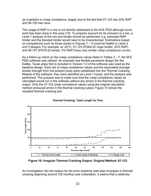
as it pertains to creep compliance, largely due to the fact that 07-123 has 20% RAP<strong>and</strong> 06-125 has none.The usage <strong>of</strong> RAP in a mix is not directly addressed in the M-E PDG although somework has been done in this area (10). To properly account for its inclusion in a mix, aLevel 1 analysis <strong>of</strong> the mix <strong>and</strong> binder should be performed; e.g. extracted RAPbinder <strong>and</strong> the blended binder would need to be characterized. Estimations basedon comparisons such as those shown in Figures 7 – 9 could be helpful in Level 2<strong>and</strong> 3 designs. For example, at -20°C, 07-123 (PG64-22 virgin binder, 20% RAP)<strong>and</strong> 06-101 (PG76-22 binder, 0% RAP) have very similar creep compliance curves.As a follow-up check on the creep compliance values listed in Tables 3 – 7, the M-EPDG s<strong>of</strong>tware was utilized. An example new flexible pavement design (for theDallas, Texas area) that is included in Version 1.0 <strong>of</strong> the s<strong>of</strong>tware was used as thebaseline design. Each set <strong>of</strong> creep compliance values <strong>and</strong> the associated averagetensile strength from the present study were substituted into the Thermal CrackingModule <strong>of</strong> the s<strong>of</strong>tware, they were identified as Level 1 inputs, <strong>and</strong> the analysis wasperformed. The purpose was to make sure that the creep compliance values ascalculated would run in the s<strong>of</strong>tware without any errors in the thermal crackingoutput. Only the 07-123 creep compliance values using the original calculationmethod produced errors in the thermal cracking output. Figure 10 shows theresultant thermal cracking plot.Thermal Cracking: Total Length Vs Time500400Total Length (ft/mi)30020010000 24 48 72 96 120 144 168 192 216 240 264Pavement Age (month)Thermal Crack Length Crack Length at Reliability Design LimitFigure 10: Irregular Thermal Cracking Output: Original Method: 07-123An investigation into the reason for the error (extreme stair-step increases in thermalcracking beginning around 100 months) was undertaken. It seems that a relatively22