
You also want an ePaper? Increase the reach of your titles
YUMPU automatically turns print PDFs into web optimized ePapers that Google loves.
HIMax System 3 Product Description<br />
2<br />
9.8 km<br />
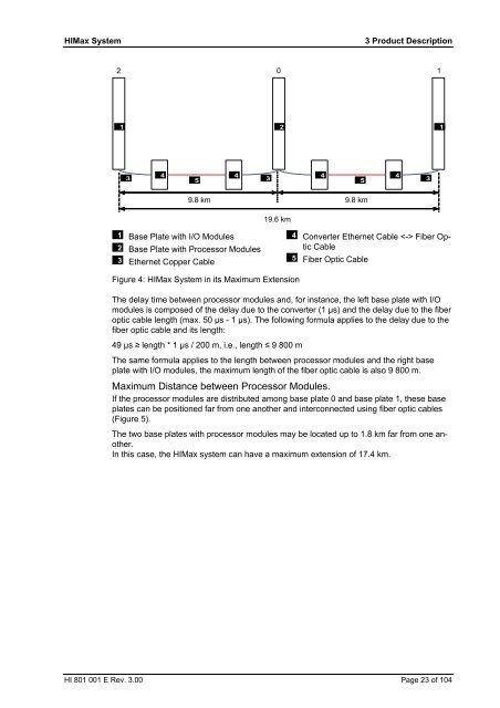
Base Plate with I/O Modules<br />
Base Plate with Processor Modules<br />
Ethernet Copper Cable<br />
0 1<br />
19.6 km<br />
Figure 4: HIMax System in its Maximum Extension<br />
9.8 km<br />
Converter Ethernet Cable Fiber Optic<br />
Cable<br />
Fiber Optic Cable<br />
The delay time between processor modules and, for instance, the left base plate with I/O<br />
modules is composed of the delay due to the converter (1 µs) and the delay due to the fiber<br />
optic cable length (max. 50 µs - 1 µs). The following formula applies to the delay due to the<br />
fiber optic cable and its length:<br />
49 µs ≥ length * 1 µs / 200 m, i.e., length ≤ 9 800 m<br />
The same formula applies to the length between processor modules and the right base<br />
plate with I/O modules, the maximum length of the fiber optic cable is also 9 800 m.<br />
Maximum Distance between Processor Modules.<br />
If the processor modules are distributed among base plate 0 and base plate 1, these base<br />
plates can be positioned far from one another and interconnected using fiber optic cables<br />
(Figure 5).<br />
The two base plates with processor modules may be located up to 1.8 km far from one another.<br />
In this case, the HIMax <strong>system</strong> can have a maximum extension of 17.4 km.<br />
HI 801 001 E Rev. 3.00 Page 23 of 104