
Create successful ePaper yourself
Turn your PDF publications into a flip-book with our unique Google optimized e-Paper software.
HIMax System 9 Life Cycle<br />
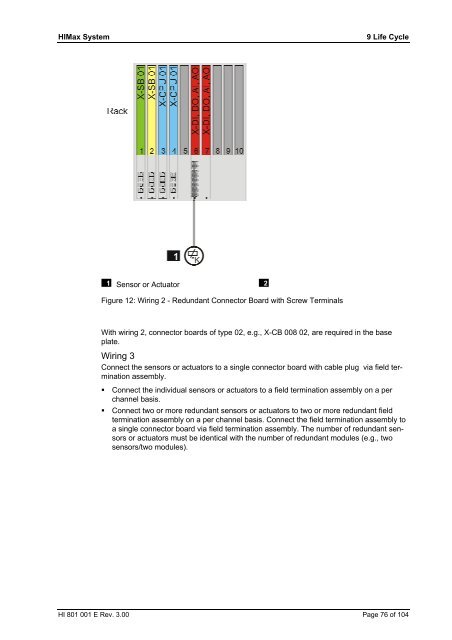
Sensor or Actuator<br />
Figure 12: Wiring 2 - Redundant Connector Board with Screw Terminals<br />
With wiring 2, connector boards of type 02, e.g., X-CB 008 02, are required in the base<br />
plate.<br />
Wiring 3<br />
Connect the sensors or actuators to a single connector board with cable plug via field termination<br />
assembly.<br />
� Connect the individual sensors or actuators to a field termination assembly on a per<br />
channel basis.<br />
� Connect two or more redundant sensors or actuators to two or more redundant field<br />
termination assembly on a per channel basis. Connect the field termination assembly to<br />
a single connector board via field termination assembly. The number of redundant sensors<br />
or actuators must be identical with the number of redundant modules (e.g., two<br />
sensors/two modules).<br />
HI 801 001 E Rev. 3.00 Page 76 of 104