
You also want an ePaper? Increase the reach of your titles
YUMPU automatically turns print PDFs into web optimized ePapers that Google loves.
HIMax System 7 Diagnosis<br />
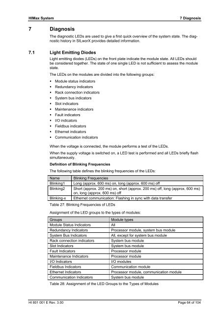
7 Diagnosis<br />
The diagnostic LEDs are used to give a first quick overview of the <strong>system</strong> state. The diagnostic<br />
history in SILworX provides detailed information.<br />
7.1 Light Emitting Diodes<br />
Light emitting diodes (LEDs) on the front plate indicate the module state. All LEDs should<br />
be considered together. The state of one single LED is not sufficient to assess the module<br />
state.<br />
The LEDs on the modules are divided into the following groups:<br />
� Module status indicators<br />
� Redundancy indicators<br />
� Rack connection indicators<br />
� System bus indicators<br />
� Slot indicators<br />
� Maintenance indicators<br />
� Fault indicators<br />
� I/O indicators<br />
� Fieldbus indicators<br />
� Ethernet indicators<br />
� Communication indicators<br />
When the voltage is connected, the module performs a test of the LEDs.<br />
When the supply voltage is switched on, a LED test is performed and all LEDs briefly flash<br />
simultaneously.<br />
Definition of Blinking Frequencies<br />
The following table defines the blinking frequencies of the LEDs:<br />
Name Blinking Frequencies<br />
Blinking1 Long (approx. 600 ms) on, long (approx. 600 ms) off<br />
Blinking2 Short (approx. 200 ms) on, short (approx. 200 ms) off, long (approx. 600 ms)<br />
on, long (approx. 600 ms) off<br />
Blinking-x Ethernet communication: Flashing in sync with data transfer<br />
Table 27: Blinking Frequencies of LEDs<br />
Assignment of the LED groups to the types of modules:<br />
Groups Module types<br />
Module Status Indicators All<br />
Redundancy Indicators Processor module, <strong>system</strong> bus module<br />
System Bus Indicators All, except for <strong>system</strong> bus module<br />
Rack connection indicators System bus module<br />
Slot Indicators System bus module<br />
Fault Indicators Processor module<br />
Maintenance Indicators Processor module<br />
I/O Indicators I/O modules<br />
Fieldbus Indicators Communication module<br />
Ethernet Indicators Processor module, communication module<br />
Communication Indicators System bus module<br />
Table 28: Assignment of the LED Groups to the Types of Modules<br />
HI 801 001 E Rev. 3.00 Page 64 of 104