

EDS3365 Manual in PDF format - Bender
EDS3365 Manual in PDF format - Bender
EDS3365 Manual in PDF format - Bender
- No tags were found...

Create successful ePaper yourself
Turn your PDF publications into a flip-book with our unique Google optimized e-Paper software.
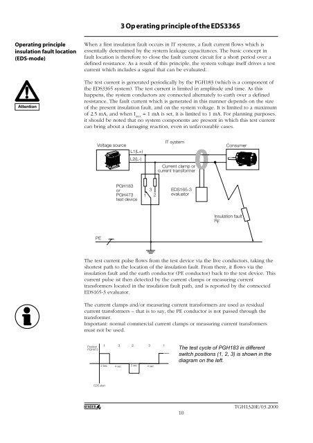
3 Op erat<strong>in</strong>g pr<strong>in</strong>ciple of the <strong>EDS3365</strong>Operat<strong>in</strong>g pr<strong>in</strong>ciple<strong>in</strong>sulation fault location(EDS-mode)AttentionWhen a first <strong>in</strong>sulation fault occurs <strong>in</strong> IT systems, a fault current flows which isessentially determ<strong>in</strong>ed by the system leakage capacitances. The basic concept <strong>in</strong>fault location is therefore to close the fault current circuit for a short period over adef<strong>in</strong>ed resistance. As a result of this pr<strong>in</strong>ciple, the system voltage itself drives a testcurrent which <strong>in</strong>cludes a signal that can be evaluated.The test current is generated periodically by the PGH183 (which is a component ofthe <strong>EDS3365</strong> system). The test current is limited <strong>in</strong> amplitude and time. As thishappens, the system conductors are connected alternately to earth over a def<strong>in</strong>edresistance. The fault current which is generated <strong>in</strong> this manner depends on the sizeof the present <strong>in</strong>sulation fault, and on the system voltage. It is limited to a maximumof 2.5 mA, and when I max= 1 mA is set, it is limited to 1 mA. For plann<strong>in</strong>g purposes,it should be noted that no system components are present <strong>in</strong> which this test currentcan br<strong>in</strong>g about a damag<strong>in</strong>g reaction, even <strong>in</strong> unfavourable cases.Voltage sourceL1(L+)IT systemConsumerL2(L-)Current clamp orcurrent transformerPGH183orPGH473test device132EDS165-3evaluatorInsulation faultRFPEThe test current pulse flows from the test device via the live conductors, tak<strong>in</strong>g theshortest path to the location of the <strong>in</strong>sulation fault. From there, it flows via the<strong>in</strong>sulation fault and the earth conductor (PE conductor) back to the test device. Thiscurrent pulse ist then detected by the current clamps or measur<strong>in</strong>g currenttransformers located <strong>in</strong> the <strong>in</strong>sulation fault path, and is reported by the connectedEDS165-3 evaluator.The current clamps and/or measur<strong>in</strong>g current transformers are used as residualcurrent transformers – that is to say, the PE conductor is not passed through thetransformer.Important: normal commercial current clamps or measur<strong>in</strong>g current transformersmust not be used.PositionPGH4731 3 2 3 12 sec 4 sec 2 sec 4 secThe test cycle of PGH183 <strong>in</strong> differentswitch positions (1, 2, 3) is shown <strong>in</strong> thediagram on the left.EDS start10TGH1320E/03.2000


