

EDS3365 Manual in PDF format - Bender
EDS3365 Manual in PDF format - Bender
EDS3365 Manual in PDF format - Bender
- No tags were found...

Create successful ePaper yourself
Turn your PDF publications into a flip-book with our unique Google optimized e-Paper software.
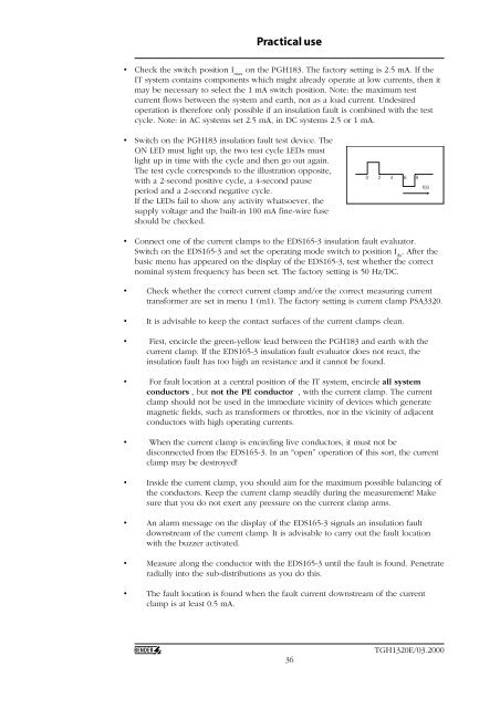
Practical use• Check the switch position I maxon the PGH183. The factory sett<strong>in</strong>g is 2.5 mA. If theIT system conta<strong>in</strong>s components which might already operate at low currents, then itmay be necessary to select the 1 mA switch position. Note: the maximum testcurrent flows between the system and earth, not as a load current. Undesiredoperation is therefore only possible if an <strong>in</strong>sulation fault is comb<strong>in</strong>ed with the testcycle. Note: <strong>in</strong> AC systems set 2.5 mA, <strong>in</strong> DC systems 2.5 or 1 mA.• Switch on the PGH183 <strong>in</strong>sulation fault test device. TheON LED must light up, the two test cycle LEDs mustlight up <strong>in</strong> time with the cycle and then go out aga<strong>in</strong>.The test cycle corresponds to the illustration opposite,with a 2-second positive cycle, a 4-second pauseperiod and a 2-second negative cycle.If the LEDs fail to show any activity whatsoever, thesupply voltage and the built-<strong>in</strong> 100 mA f<strong>in</strong>e-wire fuseshould be checked.0 2 4 6 8t(s)• Connect one of the current clamps to the EDS165-3 <strong>in</strong>sulation fault evaluator.Switch on the EDS165-3 and set the operat<strong>in</strong>g mode switch to position I ∆s. After thebasic menu has appeared on the display of the EDS165-3, test whether the correctnom<strong>in</strong>al system frequency has been set. The factory sett<strong>in</strong>g is 50 Hz/DC.• Check whether the correct current clamp and/or the correct measur<strong>in</strong>g currenttransformer are set <strong>in</strong> menu 1 (m1). The factory sett<strong>in</strong>g is current clamp PSA3320.• It is advisable to keep the contact surfaces of the current clamps clean.• First, encircle the green-yellow lead between the PGH183 and earth with thecurrent clamp. If the EDS165-3 <strong>in</strong>sulation fault evaluator does not react, the<strong>in</strong>sulation fault has too high an resistance and it cannot be found.• For fault location at a central position of the IT system, encircle all systemconductors , but not the PE conductor , with the current clamp. The currentclamp should not be used <strong>in</strong> the immediate vic<strong>in</strong>ity of devices which generatemagnetic fields, such as transformers or throttles, nor <strong>in</strong> the vic<strong>in</strong>ity of adjacentconductors with high operat<strong>in</strong>g currents.• When the current clamp is encircl<strong>in</strong>g live conductors, it must not bedisconnected from the EDS165-3. In an "open” operation of this sort, the currentclamp may be destroyed!• Inside the current clamp, you should aim for the maximum possible balanc<strong>in</strong>g ofthe conductors. Keep the current clamp steadily dur<strong>in</strong>g the measurement! Makesure that you do not exert any pressure on the current clamp arms.• An alarm message on the display of the EDS165-3 signals an <strong>in</strong>sulation faultdownstream of the current clamp. It is advisable to carry out the fault locationwith the buzzer activated.• Measure along the conductor with the EDS165-3 until the fault is found. Penetrateradially <strong>in</strong>to the sub-distributions as you do this.• The fault location is found when the fault current downstream of the currentclamp is at least 0.5 mA.36TGH1320E/03.2000


