

EDS3365 Manual in PDF format - Bender
EDS3365 Manual in PDF format - Bender
EDS3365 Manual in PDF format - Bender
- No tags were found...

Create successful ePaper yourself
Turn your PDF publications into a flip-book with our unique Google optimized e-Paper software.
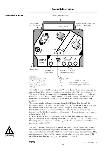
Product descriptionTest device PGH183solid cas<strong>in</strong>g with gripeurosocket forcold conditionsON/OFF switchselector switch for max. testcurrent (2.5 / 1 mA)ONUs2,5mAImax100mAON1 mAL1(+)AC/DCL2(-)L3PGH183Fuse 100mAsocket for PEconnection3 sockets for coupl<strong>in</strong>g tothe electrical systemNot visible:magnetic adhesive stripon the rear side of thehous<strong>in</strong>g to fasten ontometal parts (e.g. switchcab<strong>in</strong>et)Display LEDs:ONPower on LED<strong>in</strong>dicates positive test cycle<strong>in</strong>dicates negative test cycleThe PGH183 is activated by us<strong>in</strong>g its ON/OFF switch, and it generates a def<strong>in</strong>ed testcurrent signal. The voltage present <strong>in</strong> the system is used to drive the test current.The value of the test current which is generated therefore depends on the value ofthe <strong>in</strong>sulation fault that is present, and on the system voltage. The test current islimited to a maximum of 2.5 mA or to 1 mA when the switch is under the 1mAposition.The test current flows from the system via the PGH183 and then through theprotective conductor (PE) and the <strong>in</strong>sulation fault (or faults) back to the system. Thetest current signal is detected by the current clamps or measur<strong>in</strong>g currenttransformers located <strong>in</strong> the fault current circuit, and the defective circuits are<strong>in</strong>dicated by the EDS165-3 <strong>in</strong>sulation fault evaluator whenever the response value of0.5 mA is exceeded.If the PGH183 is active, the cycle LEDs light up alternately <strong>in</strong> time with the testcycle. If the device is connected by term<strong>in</strong>als L1, L2, L3 (or L1, L2) to a system that islive for operational reasons the term<strong>in</strong>al must not be disconnected from theprotective conductor (PE).AttentionThe test current flows between the system and earth. If unfavourable comb<strong>in</strong>ationsof circumstances arise (low-impedance <strong>in</strong>sulation fault <strong>in</strong> comb<strong>in</strong>ation with the testcycle), control errors cannot be ruled out on very sensitive system components (SPC,m<strong>in</strong>iature relays). This possibility should be taken <strong>in</strong>to account prior to use. If thispossiblity exists, then sett<strong>in</strong>g I max= 1 mA should be selected.18TGH1320E/03.2000


