JRC Launcher V2 Operation Manual 21 Sep. 2010, Revision 1.7
JRC Launcher V2 Operation Manual 21 Sep. 2010, Revision 1.7
JRC Launcher V2 Operation Manual 21 Sep. 2010, Revision 1.7

You also want an ePaper? Increase the reach of your titles
YUMPU automatically turns print PDFs into web optimized ePapers that Google loves.
<strong>JRC</strong> <strong>Launcher</strong> <strong>V2</strong> <strong>Operation</strong> <strong>Manual</strong>, <strong>21</strong> <strong>Sep</strong>. <strong>2010</strong>, <strong>Revision</strong> <strong>1.7</strong><strong>JRC</strong> <strong>Launcher</strong> <strong>V2</strong> <strong>Operation</strong> <strong>Manual</strong><strong>21</strong> <strong>Sep</strong>. <strong>2010</strong>, <strong>Revision</strong> <strong>1.7</strong>Japan Radio Co., Ltd.Japan Radio Co., Ltd.1/75
<strong>JRC</strong> <strong>Launcher</strong> <strong>V2</strong> <strong>Operation</strong> <strong>Manual</strong>, <strong>21</strong> <strong>Sep</strong>. <strong>2010</strong>, <strong>Revision</strong> <strong>1.7</strong>Contents1. INTRODUCTION ................................... 31.1. WHAT IS <strong>JRC</strong> LAUNCHER <strong>V2</strong>?............ 31.2. FUNCTION TABLE............................... 31.3. RELATED DOCUMENT......................... 31.4. OPERATION ENVIRONMENT................ 31.5. TCP PORT NUMBER ........................... 31.6. CONFIGURATION FILE ........................ 32. SETTING UP .......................................... 32.1. UPGRADE ........................................... 32.2. INSTALL.............................................. 32.3. START-UP............................................ 32.4. INITIAL SETTING ................................ 32.5. UNINSTALL......................................... 33. USING <strong>JRC</strong> LAUNCHER <strong>V2</strong> ................. 33.1. LOG-IN ............................................... 33.2. LOG-OUT ............................................ 34. OBSERVING DEVICE CONDITION ..... 35. COMMUNICATING................................ 35.1. STANDARD IP CONNECTION................ 35.1.1. How to browse a internet web page byStandard IP connection........................................35.2. CONNECTING BY STREAMING IPCONNECTION................................................. 35.2.1. Introduction .........................................35.2.2. Difference with Standard Connection 36. DETAILS OF EACH SCREEN ............... 36.1. COMMONNESS .................................... 36.2. MES CONT SCREEN.......................... 36.3. PHONE BOOK SCREEN.................... 36.4. CALL LOG SCREEN........................... 36.5. SELF TEST SCREEN ......................... 36.6. ALARM PACK SCREEN..................... 36.7. STANDARD SCREEN......................... 36.7.1. Connect and disconnect own terminal36.7.2. Connect and disconnect other terminals(Multiple-connection) ...........................................36.8. STREAMING SCREEN ...................... 36.9. SMS SCREEN ..................................... 36.9.1. New Message .......................................36.9.2. Inbox ....................................................36.9.3. Sent ......................................................36.9.4. Draft.....................................................36.9.5. Setting & Information .........................36.10. SETUP SCREEN................................. 36.11. PORT CONTROL SCREEN ................36.12. PORT SCREEN....................................36.13. USER SCREEN ...................................36.14. AUTO DISCONNECT SCREEN .........36.15. SIM MENU SCREEN ..........................36.16. NETWORK SCREEN ..........................36.16.1. APN Profile ......................................... 36.16.2. Packet Filter ....................................... 36.17. OPTION SCREEN(ONLY FB500 CAN BESELECTED.) ...................................................36.18. EXPORT SCREEN ..............................36.19. IMPORT SCREEN...............................37. DIFFERENCE BY CONNECTED MAINUNIT(FB250 AND FB500)............................ 38. ERROR CODE......................................... 39. EXPORT FILE ........................................ 310. FAQ.......................................................... 311. REVISION HISTORY ............................. 3Japan Radio Co., Ltd.2/75
<strong>JRC</strong> <strong>Launcher</strong> <strong>V2</strong> <strong>Operation</strong> <strong>Manual</strong>, <strong>21</strong> <strong>Sep</strong>. <strong>2010</strong>, <strong>Revision</strong> <strong>1.7</strong>1. INTRODUCTION1.1. What is <strong>JRC</strong> <strong>Launcher</strong> <strong>V2</strong>?<strong>JRC</strong> <strong>Launcher</strong> <strong>V2</strong> is Windows application to communicate by using various operations of BGANterminal JUE-250/500. As a rule, the function that corresponds to FB500 OIU-WEB is installed.However this <strong>Launcher</strong> cannot set route information and <strong>JRC</strong> LAN. Moreover, when FB250 isconnected, a special function only for FB500 cannot be used.The table for the function based on <strong>JRC</strong> <strong>Launcher</strong> <strong>V2</strong> is shown below.1.2. Function TableComparison between <strong>JRC</strong> <strong>Launcher</strong> <strong>V2</strong>(<strong>V2</strong>), OIU-WEB and LaunchPad is shown below.Table 1 Function comparison Table (1/2)No Function <strong>V2</strong> WEB LP Description1 Whole display ○ ○ △ A thing always displayed.2Display during PScommunication○ ○ ○ It displays while PS communication.3Display during CScommunication○ ○ × It displays while CS communication.4 SMS newly arrived notification ○ ○ ○ This notifies SMS newly arrived. (*1)5 Receiving level display ○ ○ ○ Current receiving status (Signal Quality) is displayed.6 System version display ○ ○ ○ The system version SYSXX.YY is displayed.7 Log-in ○ ○ × The user who registered with WEB is authenticated.8 MES CONT ○ ○ △This clears the state display, Heading (Only at GYRO) of each device,and the satellite search and the TX alarm.9 PHONE BOOK ○ △ ○Reading, writing and deleting are possible.WEB can be operated up to 100, and it is possible to operate with all SIMexcluding this.10 CALL LOG ○ ○ × Display, deletion, and FILE output of the call log are possible.11 SELF TEST ○ ○ × The connection state of ADE and HS is displayed.12 ALARM PACK ○ ○ ×Alarm history, existing state, Version of each device, and serial No aredisplayed.13 STANDARD CONNECTION(*2) ○ ○ △STANDARD connection is carried out.Also <strong>V2</strong> and WEB can make Standard IP connection for other terminal.Moreover, the connection state at the other terminal can be displayed,and it can be disconnected.14 STREAMING CONNECTION(*2) ○ ○ △STREAMING connection is carried out.Also <strong>V2</strong> and WEB can make Streaming IP connection for other terminal.Moreover, the connection state at the other terminal can be displayed,and it can be disconnected.15 SMS ○ ○ ○ Making SMS, transmitting, saving, receiving are possible.16 SETUP ○ ○ × This sets the entire device.17 PORT CONTROL ○ ○ × This sets Handset and TEL1/TEL2.18 PORT △ ○ × This sets ISDN, Handset, and Ethernet.19 MSN setting ○ ○ × This sets MSN.20 Handset setting ○ ○ × This sets Handset dimmer etc.<strong>21</strong> Main unit IP setting ○ ○ × This sets main unit IP.(*3)22 RAS setting × ○ × This sets validity/invalidity of RAS and IP.23 Routing setting × ○ × This sets routing.Japan Radio Co., Ltd.3/75
<strong>JRC</strong> <strong>Launcher</strong> <strong>V2</strong> <strong>Operation</strong> <strong>Manual</strong>, <strong>21</strong> <strong>Sep</strong>. <strong>2010</strong>, <strong>Revision</strong> <strong>1.7</strong>Table 2 Function comparison Table (2/2)No Function <strong>V2</strong> WEB LP Description24 USER ○ ○ ×This executes the user's registration and deletion.Also this can define a usable communication setting (APN Profile) andpermission setting to controlling other terminals connection to each user.It uses also for the No.7 Log-in.25 AUTO DISCONNECT ○ ○ × This sets the time automatically cut.26 SIM MENU ○ ○ ○ This changes the state display of SIM, PIN and PIN input.27 NETWORK ○ ○ × This sets PS communication setting: APN Profile and Packet filter.28 APN Profile ○ ○ × This registers APN/Username/Password/Global IP setting29 Packet filter ○ ○ × This executes the packet filter's registration and deletion.30 OPTION ○ ○ × This sets buzzer, button, TEL3-6, external GPS, and VDR.31 EXPORT ○ ○ × This saves a set value in the external file. (*4)(*5)32 IMPORT ○ ○ × This returns the main unit a set value in which EXPORT is done. (*3)(*4)(*1) This is displayed only when new arriving on while the application is starting. (*2) Some of the function will be restrictedby the user authorization. (*3) When main unit IP is changed, it is disconnected once. (*4) There is six kinds of data thatEXPORT can do about SETUP/PORT CONTROL/PORT/USER /AUTO DISCONNECT/OPTION/NETWORK. (*5) It is notcompatible in data to which EXPORT is done with <strong>JRC</strong> <strong>Launcher</strong> <strong>V2</strong> and data to which EXPORT is done with OIU-WEB.Please do IMPORT with each tool that did EXPORT.○ shows “available”. △ shows “partial available”. × shows “not available”.Japan Radio Co., Ltd.4/75
<strong>JRC</strong> <strong>Launcher</strong> <strong>V2</strong> <strong>Operation</strong> <strong>Manual</strong>, <strong>21</strong> <strong>Sep</strong>. <strong>2010</strong>, <strong>Revision</strong> <strong>1.7</strong>1.3. Related DocumentPlease refer to the operation manual of JUE-250 or JUE-500 used for details of the explanation of theterm and the function of the main unit.1.4. <strong>Operation</strong> Environment<strong>JRC</strong> <strong>Launcher</strong> <strong>V2</strong> operates by the following OS: an English version and a Japanese version ofWindows XP / Windows Vista and Windows 7 32-bit.• Windows XP (SP3) 32-bit English• Windows XP (SP3) 32-bit Japanese• Windows VISTA (SP2) 32-bit English• Windows VISTA (SP2) 32-bit Japanese• Windows 7 32-bit English• Windows 7 32-bit JapaneseAlso <strong>JRC</strong> <strong>Launcher</strong> <strong>V2</strong> needs XGA (1024x768) resolution display or more higher because theapplication window size can not be resized.And JUE-250/500 must be upgraded to use the latest <strong>JRC</strong> <strong>Launcher</strong> <strong>V2</strong>.Table 3 <strong>JRC</strong> <strong>Launcher</strong> <strong>V2</strong> version requirement about JUE-250/500 versionJUE-250JUE-500<strong>JRC</strong> <strong>Launcher</strong> <strong>V2</strong>.0.3.X SYS01.22orSYS01.23SYS11.33 orSYS11.34<strong>JRC</strong> <strong>Launcher</strong> <strong>V2</strong>.0.4.X SYS01.24 or later SYS11.35 or laterSYS version can be checked from the Handset menu by following operation. Status - Unit Info - Mainte No.- SYSJapan Radio Co., Ltd.5/75
<strong>JRC</strong> <strong>Launcher</strong> <strong>V2</strong> <strong>Operation</strong> <strong>Manual</strong>, <strong>21</strong> <strong>Sep</strong>. <strong>2010</strong>, <strong>Revision</strong> <strong>1.7</strong>1.5. TCP Port Number<strong>JRC</strong> <strong>Launcher</strong> <strong>V2</strong> uses TCP port 1829 and 1840 of the Main unit.1.6. Configuration File<strong>JRC</strong> <strong>Launcher</strong> <strong>V2</strong> is composed of the following files.Table 4 Configuration FileFile NameDescription<strong>JRC</strong><strong>Launcher</strong><strong>V2</strong>.exe Main unit of <strong>JRC</strong><strong>Launcher</strong><strong>V2</strong>Various settings are saved in the file.If this is not, it operates by the*.confdefault value, and when setting, it isgenerated automatically.Japan Radio Co., Ltd.6/75
<strong>JRC</strong> <strong>Launcher</strong> <strong>V2</strong> <strong>Operation</strong> <strong>Manual</strong>, <strong>21</strong> <strong>Sep</strong>. <strong>2010</strong>, <strong>Revision</strong> <strong>1.7</strong>2. SETTING UPThis chapter explains how to set up <strong>JRC</strong> <strong>Launcher</strong> <strong>V2</strong>.2.1. UpgradeUpgrade the BGAN terminal if the SYS version does not meet the <strong>Operation</strong> Environment needs.2.2. InstallA suitable directory is made, and <strong>JRC</strong><strong>Launcher</strong><strong>V2</strong>.exe is put.2.3. Start-up<strong>JRC</strong><strong>Launcher</strong><strong>V2</strong>.exe is executed.2.4. Initial SettingIt is not necessary in usual use.Especially, please set it on each screen when it is necessary.2.5. UninstallEach directory made when installing is deleted.Because the registry is not used, uninstallation is completed by this.Japan Radio Co., Ltd.7/75
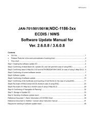
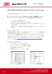
<strong>JRC</strong> <strong>Launcher</strong> <strong>V2</strong> <strong>Operation</strong> <strong>Manual</strong>, <strong>21</strong> <strong>Sep</strong>. <strong>2010</strong>, <strong>Revision</strong> <strong>1.7</strong>3. USING <strong>JRC</strong> <strong>Launcher</strong> <strong>V2</strong><strong>JRC</strong><strong>Launcher</strong><strong>V2</strong>.exe is executed.3.1. Log-inAfter <strong>JRC</strong> <strong>Launcher</strong> <strong>V2</strong> is started, the following log-in screens are displayed first.When the User name and the Password are input, and it succeeds in the authentication, the functioncorresponding to the user authentication level can be used. Put a check to save the Password.The default user name and password is “ADMIN” and “0001". In USER Screen (refer to 6.13. USERScreen), the user name and the password can be changed and be added by the setting of "USER"and "CODE" of that menu. In the initial state, it tries to connect with IP address 192.168.128.100 ofthe main unit. If IP address of the main unit has been changed, it is necessary to specify the IPaddress.Input user nameand password.Password will besaved when this ischecked.If IP address of the mainunit has been changed, itis not possible to connect.The change screen of IPaddress is displayed withthis button.When here is not"Connected", it is notpossible to authenticate.Fig. 1 Log-in ScreenWhen authentication fails, POPUP windows will be displayed, confirm User name and Password.(Refer to 11. FAQ)Japan Radio Co., Ltd.8/75
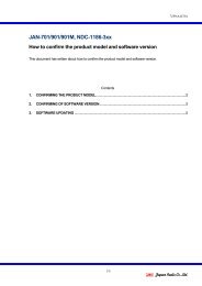
<strong>JRC</strong> <strong>Launcher</strong> <strong>V2</strong> <strong>Operation</strong> <strong>Manual</strong>, <strong>21</strong> <strong>Sep</strong>. <strong>2010</strong>, <strong>Revision</strong> <strong>1.7</strong>Fig. 2 IP Specified ScreenWhen IP address of main unit has been changed, it is necessary to specify the IP for <strong>JRC</strong> <strong>Launcher</strong>.When the IP button is pushed, the dialog of Fig.2 is displayed. Then, after it changes, IP of the mainunit is specified.If the both: IB and CM connected display of lower right is not "Connected", log-in cannot be done.Please confirm the following items when not becoming "Connected" even if it waits by about 10seconds.• Is the power supply of main unit turning on?• Is main unit connected with LAN cable?• Is not IP of main unit changed?Japan Radio Co., Ltd.9/75
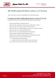
<strong>JRC</strong> <strong>Launcher</strong> <strong>V2</strong> <strong>Operation</strong> <strong>Manual</strong>, <strong>21</strong> <strong>Sep</strong>. <strong>2010</strong>, <strong>Revision</strong> <strong>1.7</strong>The MES CONT screen opens as follows when succeeding in the authentication.It is displayed from MESCONT to SMS for theGUEST user.It is possible to use from MESCONT to IMPORT by logging-inwith the ADMIN user.Fig. 3 Log-in Success3.2. Log-outIt logs out when the LOGOUT button under the MENU screen is pushed, and it returns to the log-inscreen.At that time, when the connection by <strong>JRC</strong> <strong>Launcher</strong> has already continued, the dialog that confirmswhether to disconnect or to continue is displayed.Japan Radio Co., Ltd.10/75
<strong>JRC</strong> <strong>Launcher</strong> <strong>V2</strong> <strong>Operation</strong> <strong>Manual</strong>, <strong>21</strong> <strong>Sep</strong>. <strong>2010</strong>, <strong>Revision</strong> <strong>1.7</strong>4. OBSERVING DEVICE CONDITIONThe display of the device condition always includes the display and each screen display.The typical device condition that can be referred with <strong>JRC</strong> <strong>Launcher</strong> <strong>V2</strong> is shown below, and itexplains each screen where they are displayed.Table 5 Outline in Device Condition that can be referred with <strong>JRC</strong> <strong>Launcher</strong> <strong>V2</strong>No Condition Description Displayed Screen1 System version The version of the system is always displayed.Display alwaysALARM PACK2 Each serial No IMEI, <strong>JRC</strong> No ALARM PACK3 Receiving levelDisplay alwaysSignal Quality is always displayed by the bar display.MES CONTThe REC level is displayed with MES CONT and ALARM PACK.ALARM PACK4CS communication This always displays having communication or not with an icon. Display alwaysconditionThe content of the type and time, etc. is displayed with MES CONT. MES CONTThis always displays having communication or not with an icon. Display always5PS communication The type and the terminal IP are displayed with MES CONT. MES CONTconditionThe display to CID/APN used is displayed with STANDARD STANDARDCONNECTION and STREAMING CONNECTION.STREAMING6 Newly arrived SMS A newly arrived having is always displayed with the icon. Display always7 TX alarm8 Device status9Present date andtimeThe generation of the TX alarm is displayed with MES CONT.The generation alarm is displayed with ALARM PACK.(OFF PWR, HIGH PWR, BURST are TX alarm)The device status (Correspond to the lower display of Handset) isdisplayed with MES CONT.Present date and time are displayed with MES CONT and ALARMPACK.※Accuracy (update interval) is Windows clock < MES CONT
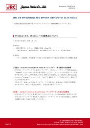
<strong>JRC</strong> <strong>Launcher</strong> <strong>V2</strong> <strong>Operation</strong> <strong>Manual</strong>, <strong>21</strong> <strong>Sep</strong>. <strong>2010</strong>, <strong>Revision</strong> <strong>1.7</strong>5. COMMUNICATINGIn <strong>JRC</strong> <strong>Launcher</strong> <strong>V2</strong>, the Standard connection and the Streaming connection can be done.ADMIN user can restrict Standard/Streaming IP connection operation against each user.(Refer to 6.13 USER screen)5.1. Standard IP connection5.1.1. How to browse a internet web page by Standard IP connectionFirst of all, to execute the Standard connection, "STANDARD" is selected from a left menu.The STANDARD CONNECTION screen is displayed.Click hereFig. 4 STANDARD ScreenJapan Radio Co., Ltd.12/75
<strong>JRC</strong> <strong>Launcher</strong> <strong>V2</strong> <strong>Operation</strong> <strong>Manual</strong>, <strong>21</strong> <strong>Sep</strong>. <strong>2010</strong>, <strong>Revision</strong> <strong>1.7</strong>Second, confirm Multiple-connection checkbook is unchecked.Third, defined APN settings.Select “SIM default”, “Network assigned”, “User defined” from APN menu. “User defined” allowsmanual APN name input to textbox. “SIM default” automatically uses the default settings in SIMcard.Fourth, defined Username and Password.Input Username and Password if it was informed and input was required from SIM card serviceprovider. (This is not the same Username and Password to log in <strong>JRC</strong> <strong>Launcher</strong> <strong>V2</strong>.)Fifth, defined Global IP address setting.Select “Dynamic” or “Static” from Global IP menu. “Static” allows defining Global IP address toassign when Standard IP connection was established. Select “Static”, if Global IP was informedand input was required from SIM card service provider.Sixth, connect Standard IP connectionPush Connect button. JUE-250/500 will try to establish Standard IP connection by using thedefined settings.Standard IP connection succeed, can be confirmed from Connection status shown at the upperposition. Connection status will change to: Idle – Connecting – Connected. And “CONNECT”button will turn to “DISCONNECT” button.Seventh, browse internet web pageEighth, disconnect Standard IP connectionPush this “DISCONNECT” button at the bottom.Standard IP disconnection succeed, can be confirmed from Connection status shown at theupper position. Connection status will change to: Disconnecting –Idle. And “DISCONNECT”button will go back to “CONNECT” button.Japan Radio Co., Ltd.13/75
<strong>JRC</strong> <strong>Launcher</strong> <strong>V2</strong> <strong>Operation</strong> <strong>Manual</strong>, <strong>21</strong> <strong>Sep</strong>. <strong>2010</strong>, <strong>Revision</strong> <strong>1.7</strong>5.2. Connecting by Streaming IP connection5.2.1. IntroductionFirst of all, to execute the Streaming connection, " STREAMING " is selected from a left menu.The STREAMING CONNECTION screen is displayed.A difference with STANDARD CONNECTION is only having RATE item or not of the SETTINGcolumn. The connection method and the disconnection method are similar to "5.1 Connecting byStandard" and refer to that, please.5.2.2. Difference with Standard ConnectionRATE sets desired communication rate (Desired) and minimum communication rate (Minimum) thatcan be allowed.It is only JUE-500 to be able to select 256K though both ranges are 8K-256K.Moreover, it should be Minimum≦Desired. (Automatically correct it. )Click here.A difference with Standard ishaving RATE or not.Fig. 5 STREAMING ScreenJapan Radio Co., Ltd.14/75
<strong>JRC</strong> <strong>Launcher</strong> <strong>V2</strong> <strong>Operation</strong> <strong>Manual</strong>, <strong>21</strong> <strong>Sep</strong>. <strong>2010</strong>, <strong>Revision</strong> <strong>1.7</strong>6. DETAILS OF EACH SCREENA detailed explanation of each screen of <strong>JRC</strong> <strong>Launcher</strong> <strong>V2</strong> is described as follows.6.1. CommonnessThe left side and the lower side on the screen are common in all screens.1012 3 456The left side and thelower side on thescreen are common inall screens.789Fig. 6 Common ScreenJapan Radio Co., Ltd.15/75
<strong>JRC</strong> <strong>Launcher</strong> <strong>V2</strong> <strong>Operation</strong> <strong>Manual</strong>, <strong>21</strong> <strong>Sep</strong>. <strong>2010</strong>, <strong>Revision</strong> <strong>1.7</strong>Table 6 Common Screen ItemsNo Item Description1 REC BarSix bars on the upper left show the reception level.The maximum is 6. It is possible to communicate with stability from3.2 CS Icon This is an icon shown while CS communication.3 PS Icon This is an icon shown while PS communication.4 SMS Newly Arrived Icon This is an icon that shows newly arrived SMS.5 Inmarsat Logo This is a logo mark.6 MENUThis is a screen selection menu.The display item changes by the authority of the user who logged in.7 LOGOUT Button This is a log-out button.8 SYSTEM VERSION This displays the system version of the main unit.9 <strong>JRC</strong> Logo This is a logo mark.10 IconThis shows <strong>JRC</strong> <strong>Launcher</strong> <strong>V2</strong> software version by clinking this icon andselecting “about <strong>JRC</strong>L”.Japan Radio Co., Ltd.16/75
<strong>JRC</strong> <strong>Launcher</strong> <strong>V2</strong> <strong>Operation</strong> <strong>Manual</strong>, <strong>21</strong> <strong>Sep</strong>. <strong>2010</strong>, <strong>Revision</strong> <strong>1.7</strong>6.2. MES CONT ScreenThe MES CONT screen displays the state of the device often referred to.Moreover, the setting of heading value (GYRO only operates), the satellite selection and the TX alarmclear can be done.24671013589111<strong>21</strong>314Fig. 7 MES CONT ScreenJapan Radio Co., Ltd.17/75
<strong>JRC</strong> <strong>Launcher</strong> <strong>V2</strong> <strong>Operation</strong> <strong>Manual</strong>, <strong>21</strong> <strong>Sep</strong>. <strong>2010</strong>, <strong>Revision</strong> <strong>1.7</strong>Table 7 MES CONT Screen ItemsNo Item Description1 STATUSThis displays the device status.It is equal to the lower display of the handset.2 DATEThis displays the time of the device. The alarm packing and the calllog are saved at this time.3 POSITION This displays the position information of the ship.4 REC This displays the receiving level.5 EIRP This displays the transmitting power level.6 SAT This displays the satellite being used now (Or search).7 SPOT This displays spot beam No being received now.8 BEARING This displays the bearing value.9 HEADING This displays the heading value. (GYRO only operates.)10 COMM STATUS This displays information on the communication at present.11 TX ALARM When the TX alarm is generated, the check mark is displayed.12 HEADING SettingThe heading value is set. The range that can be set is 0-359.(GYRO only operates. )13 Satellite SelectionThe satellite that can be selected from the pull-down menu atpresent is selected.The satellite that seems to be the best the device when AUTO isselected it is automatically selected.14 TX Alarm Clear When the TX alarm is generated, it is cleared.Japan Radio Co., Ltd.18/75
<strong>JRC</strong> <strong>Launcher</strong> <strong>V2</strong> <strong>Operation</strong> <strong>Manual</strong>, <strong>21</strong> <strong>Sep</strong>. <strong>2010</strong>, <strong>Revision</strong> <strong>1.7</strong>6.3. PHONE BOOK ScreenThe PHONE BOOK screen displays the phone book saved on SIM card.The phone book is newly made, edited, and can be deleted.Moreover, the list of the phone book can be saved in the file.<strong>21</strong>34567Fig. 8 PHONE BOOK ScreenJapan Radio Co., Ltd.19/75
<strong>JRC</strong> <strong>Launcher</strong> <strong>V2</strong> <strong>Operation</strong> <strong>Manual</strong>, <strong>21</strong> <strong>Sep</strong>. <strong>2010</strong>, <strong>Revision</strong> <strong>1.7</strong>Table 8 PHONE BOOK Screen ItemsNo Item Description1 Phone Book ListThe list of the phone book saved on SIM card is displayed.In <strong>JRC</strong> <strong>Launcher</strong> <strong>V2</strong>, 254 or less can display/edit in SIM card.However, the number that can be referred from Handset andOIU-WEB is from the top to 100 casesPlease save the phone book used with Handset and OIU-WEB fromthe top to 100 cases.2 NO.This displays NO. selected by the phone book list. (It is not possibleto edit.)3 ADDRESSThis displays ADDRESS of NO. selected by the phone book list.It is possible to edit.ADDRESS can be input up to ten characters or less.4 NUMBERThis displays NUMBER of NO. selected by the phone book list.It is possible to edit.NUMBER can be input up to 20 digits or less.5 SET Button The edit result is saved on SIM card.6 DEL Button The phone book of selected NO. is deleted.7 FILE Button The phone book list is saved in the file.Japan Radio Co., Ltd.20/75
<strong>JRC</strong> <strong>Launcher</strong> <strong>V2</strong> <strong>Operation</strong> <strong>Manual</strong>, <strong>21</strong> <strong>Sep</strong>. <strong>2010</strong>, <strong>Revision</strong> <strong>1.7</strong>6.4. CALL LOG ScreenThe CALL LOG screen displays the call log preserved in the main unit.Push the DISP button after selecting SERVICE TYPE and COMM (RECV/SEND/BOTH). Thespecified call log can be displayed. The content of the display can be saved in the file.All the call logs (all SERVICE TYPE and all directions) can be deleted by doing ALL CLEAR.It is possible to sort it by the item by clicking the item name of the list. Ascending order and thedescending order are replaced in turn whenever clicking it.1 2 3 4 56~10Fig. 9 CALL LOG ScreenJapan Radio Co., Ltd.<strong>21</strong>/75
<strong>JRC</strong> <strong>Launcher</strong> <strong>V2</strong> <strong>Operation</strong> <strong>Manual</strong>, <strong>21</strong> <strong>Sep</strong>. <strong>2010</strong>, <strong>Revision</strong> <strong>1.7</strong>11~15Fig. 10 CALL LOG ScreenJapan Radio Co., Ltd.22/75
<strong>JRC</strong> <strong>Launcher</strong> <strong>V2</strong> <strong>Operation</strong> <strong>Manual</strong>, <strong>21</strong> <strong>Sep</strong>. <strong>2010</strong>, <strong>Revision</strong> <strong>1.7</strong>Table 9 CALL LOG Screen ItemsNo Item Description1 SERVICE TYPEThis selects the service type.VOICE/FAX/STANDARD/STREAMING/SMS/UDI/RDI※UDI and RDI are only for FB500.2 COMMThis selects the direction of the communication.RECV/SEND/BOTH3 DISP Button The call log specified with SERVICE TYPE and COMM is displayed.4 FILE Button The displayed call log is saved in the file.5 ALL CLEAR ButtonAll the call logs are deleted.※Everything is deleted including the displayed call log.6 NO.This is a serial number of the call log. The number becomes small ina newer call log.7 START TIME This is time for the communication to have begun.8 CALLED NO.This is a number of the communication partner. There may not be itat the time of the receiving.9 SAT This is a satellite used to communicate.10 TIME/SIZEThis is communication time. It is a number of communication bytesin case of the STANDARD connection.11 NAMEThis is a communicated user name. In STANDARD/STREAMING,this is IP address of PC that communicated.12 COMThis is a direction of the communication. It is RECV (receive) orSEND (send).13 TERM This is a terminal that communicated or port.14 Qos This displays the communication rate only for STREAMING.15 CODE This is a cause code.Japan Radio Co., Ltd.23/75
<strong>JRC</strong> <strong>Launcher</strong> <strong>V2</strong> <strong>Operation</strong> <strong>Manual</strong>, <strong>21</strong> <strong>Sep</strong>. <strong>2010</strong>, <strong>Revision</strong> <strong>1.7</strong>6.5. SELF TEST ScreenThe SELF TEST screen displays the connection state of ADE and Handset.When it is connecting it, "success" is displayed.When it is not connecting it, "failure detected" is displayed.Fig. 11 SELF TEST ScreenJapan Radio Co., Ltd.24/75
<strong>JRC</strong> <strong>Launcher</strong> <strong>V2</strong> <strong>Operation</strong> <strong>Manual</strong>, <strong>21</strong> <strong>Sep</strong>. <strong>2010</strong>, <strong>Revision</strong> <strong>1.7</strong>6.6. ALARM PACK ScreenThe ALARM PACK screen displays an alarm list, various versions, and Serial No.When a past history is referred, the history is selected from the pull-down menu.The content of the display can be saved in the file.1243Fig. 12 ALARM PACK ScreenJapan Radio Co., Ltd.25/75
<strong>JRC</strong> <strong>Launcher</strong> <strong>V2</strong> <strong>Operation</strong> <strong>Manual</strong>, <strong>21</strong> <strong>Sep</strong>. <strong>2010</strong>, <strong>Revision</strong> <strong>1.7</strong>Table 10 ALARM PACK Screen ItemsNo Item Description1SERIAL NO. &This displays IMEI, <strong>JRC</strong> NO., and maintenance NO. of eachMAINTENANCE NO. software.2 Pull-down MenuThis displays CURRENT, the saved history, and the date by the list.This is selected, and the following list display is switched.3 Content of Alarm PackThis displays the content of the alarm pack selected by thepull-down menu.The value one by one changes when CURRENT is selected.The content of each item is equal to Handset and OIU-WEB.4 FILE Button This saves the content of pack of all the alarms in the file.Japan Radio Co., Ltd.26/75
<strong>JRC</strong> <strong>Launcher</strong> <strong>V2</strong> <strong>Operation</strong> <strong>Manual</strong>, <strong>21</strong> <strong>Sep</strong>. <strong>2010</strong>, <strong>Revision</strong> <strong>1.7</strong>6.7. STANDARD ScreenIn this screen, the STANDARD connection can be made for own/other terminal.12346891171013512Fig. 13 STANDARD ScreenJapan Radio Co., Ltd.27/75
<strong>JRC</strong> <strong>Launcher</strong> <strong>V2</strong> <strong>Operation</strong> <strong>Manual</strong>, <strong>21</strong> <strong>Sep</strong>. <strong>2010</strong>, <strong>Revision</strong> <strong>1.7</strong>6.7.1. Connect and disconnect own terminalNOTE: User can not make connection if Profile setting in USER screen is “OFF”.User can connect and disconnect own terminals by following procedure:1. Confirm the Multiple-connection check-box (No.5) is unchecked.2. Select one of the profiles (No.7). If <strong>Manual</strong> is selected, input APN parameters (No.8-11).Note that the Profile cannot be selected if user is restricted in USER screen.3. Push the CONNECT button (No.13). When connection successes, connection information will beadded to the Connection List (No.2) and CONNECT button (No.13) will turn to DISCONNECTbutton (No.13).4. When disconnecting the connection, push the DISCONNECT button (No.13).6.7.2. Connect and disconnect other terminals (Multiple-connection)NOTE: To make Multiple-connection, user must be checked MULTI setting in USER screen.User can connect and disconnect other terminals by following procedure:1. Check the Multiple-connection check-box (No.5).2. Input a Local IP address (No.6) of the terminal3. Select one of the profiles (No.7). If <strong>Manual</strong> is selected, input APN parameters (No.8-11).Note that the Profile cannot be selected if user is restricted in USER screen.4. Push the CONNECT button (No.13). When connection successes, connection information will beadded to the Connection List (No.2).5. When disconnecting the connection, select the connection information from Connection list andpush the DISCONNECT button (No.4).Japan Radio Co., Ltd.28/75
<strong>JRC</strong> <strong>Launcher</strong> <strong>V2</strong> <strong>Operation</strong> <strong>Manual</strong>, <strong>21</strong> <strong>Sep</strong>. <strong>2010</strong>, <strong>Revision</strong> <strong>1.7</strong>Table 11 STANDARD Screen Items (1/2)No Item Description1 Connection statusConnection state of the own terminal. States are Idle (notconnection), Connecting, Connected, and Disconnecting.Also Disconnecting (Other PC) will be displayed by pushing No.4button.Displays the own terminal and other terminal during PS connection.• ACT: This indicates whether the context is connected or not. *will be displayed when the context is connected.• CID: This is an ID for PS connection. The ID will be 1–11.2 Connection list• IP: This is an IP address of the terminal. Own terminal will bedisplayed as “This PC”.• Global IP: This is an assigned global IP address.• SERVICE TYPE: This displays the PS connected type:Standard or Streaming.APN: This displays the Access Point Name (APN) in use.3 UPDATE Button Connection list can be renewed with this button.4 DISCONNECT ButtonThe connection selected in Connection list can be disconnected bythis button. Need to check MULTI in USER screen.5Multiple-connection Check the box to connect other terminal. Need to check MULTI inCheck-boxUSER screen.6 Local IPInput the Local IP address of other terminal to connect. Need tocheck Multiple-connection Check-box.7 ProfileSelect Profile 1-5/<strong>Manual</strong> for PS connection.When “Profile 1-5” is selected, APN Profile defined at NETWORKscreen is used.When “<strong>Manual</strong>” is selected, APN/Username/Password/Global IPcan be modified manually.Japan Radio Co., Ltd.29/75
<strong>JRC</strong> <strong>Launcher</strong> <strong>V2</strong> <strong>Operation</strong> <strong>Manual</strong>, <strong>21</strong> <strong>Sep</strong>. <strong>2010</strong>, <strong>Revision</strong> <strong>1.7</strong>Table 12 STANDARD Screen Items (2/2)No Item Description8 APNSelect SIM Default/Network assigned/User defined.When User Defined is selected, need to input APN.It is provided from SIM card provider.9 Username Input the user name. It is provided from SIM card provider.10 Password Input the password. It is provided from SIM card provider.11 Global IPSelect Dynamic (dynamic allocation) or Static (static allocation).When Static is selected, need to input IP address.It is provided from SIM card provider.12 SET Button Registers the APN/Username/Password/Global IP.13Makes a connection.CONNECT ButtonWhen connection successes, CONNECT button will turn to(on bottom of screen)DISCONNECT button.Japan Radio Co., Ltd.30/75
<strong>JRC</strong> <strong>Launcher</strong> <strong>V2</strong> <strong>Operation</strong> <strong>Manual</strong>, <strong>21</strong> <strong>Sep</strong>. <strong>2010</strong>, <strong>Revision</strong> <strong>1.7</strong>6.8. STREAMING ScreenIn this screen, the STEAMING connection can be made for own/other terminal.STREAMING screen has a communication rate setting: Desired rate and Minimum rate..12346891171051<strong>21</strong>31415Fig. 14 STREAMING ScreenJapan Radio Co., Ltd.31/75
<strong>JRC</strong> <strong>Launcher</strong> <strong>V2</strong> <strong>Operation</strong> <strong>Manual</strong>, <strong>21</strong> <strong>Sep</strong>. <strong>2010</strong>, <strong>Revision</strong> <strong>1.7</strong>Table 13 STREAMING Screen items (1/2)No Item Description1 Connection statusConnection state of the own terminal. States are Idle (notconnection), Connecting, Connected, and Disconnecting.Also Disconnecting (Other PC) will be displayed by pushing No.4button.Displays the own terminal and other terminal during PS connection.• ACT: This indicates whether the context is connected or not. *will be displayed when the context is connected.• CID: This is an ID for PS connection. The ID will be 1–11.2 Connection list• IP: This is an IP address of the terminal. Own terminal will bedisplayed as “This PC”.• Global IP: This is an assigned global IP address.• SERVICE TYPE: This displays the PS connected type:Standard or Streaming.APN: This displays the Access Point Name (APN) in use.3 UPDATE Button Connection list can be renewed with this button.4 DISCONNECT ButtonThe connection selected in Connection list can be disconnected bythis button. Need to check MULTI in USER screen.5Multiple-connection Check the box to connect other terminal. Need to check MULTI inCheck-boxUSER screen.6 Local IPInput the Local IP address of other terminal to connect. Need tocheck Multiple-connection Check-box.7 ProfileSelect Profile 1-5/<strong>Manual</strong> for PS connection.When “Profile 1-5” is selected, APN Profile defined at NETWORKscreen is used.When “<strong>Manual</strong>” is selected, APN/Username/Password/Global IPcan be modified manually.Japan Radio Co., Ltd.32/75
<strong>JRC</strong> <strong>Launcher</strong> <strong>V2</strong> <strong>Operation</strong> <strong>Manual</strong>, <strong>21</strong> <strong>Sep</strong>. <strong>2010</strong>, <strong>Revision</strong> <strong>1.7</strong>Table 14 STREAMING Screen items (2/2)No Item Description8 APNSelect SIM Default/Network assigned/User defined.When User Defined is selected, need to input APN.It is provided from SIM card provider.9 Username Input the user name. It is provided from SIM card provider.10 Password Input the password. It is provided from SIM card provider.11 Global IPSelect Dynamic (dynamic allocation) or Static (static allocation).When Static is selected, need to input IP address.It is provided from SIM card provider.12 DesiredSelect communication speed rate: 8K – 256K byte/sec wants to begranteed (desired rate).256K can be selected only with FB500.13 MinimumSelect communication speed rate: 8K – 256K byte/sec needs to begranteed (minimum rate). The minimum rate must be some orslower than the desired rate.256K can be selected only with FB500.14 SET Button Registers the APN/Username/Password/Global IP.15Makes a connection.CONNECT ButtonWhen connection successes, CONNECT button will turn to(on bottom of screen)DISCONNECT button.Japan Radio Co., Ltd.33/75
<strong>JRC</strong> <strong>Launcher</strong> <strong>V2</strong> <strong>Operation</strong> <strong>Manual</strong>, <strong>21</strong> <strong>Sep</strong>. <strong>2010</strong>, <strong>Revision</strong> <strong>1.7</strong>6.9. SMS ScreenThe SMS sending, receiving, and editing are possible on the SMS screen. Moreover, it is possible toset for the sending and the receiving of SMS.The SMS screen can be switched to the following five by the pull-down menu.• New Message (new message making)• Inbox (receiving message)• Sent (message that has been sent)• Draft (un-send (draft) message)• Setting & InformationEach content is explained at the following.6.9.1. New MessageA new message is made.After the address is specified when a new message is input, the message is sent. About the address,it is possible to input directly, and the phone book can be referred to.<strong>21</strong>5346 7 8Fig. 15 SMS-New Message ScreenJapan Radio Co., Ltd.34/75
<strong>JRC</strong> <strong>Launcher</strong> <strong>V2</strong> <strong>Operation</strong> <strong>Manual</strong>, <strong>21</strong> <strong>Sep</strong>. <strong>2010</strong>, <strong>Revision</strong> <strong>1.7</strong>Table 15 SMS-New Message Screen ItemsNo Item Description1 Pull-down Menu This switches the screen.2 To The phone number of the address is input here.ADDRESS registered in the phone book displays the list by the3 Refer to Phonebookpull-down menu.The number of the phone book selected there is input to the columnof To.The message that is sent is input here.The number of characters of messages that can be input is4displayed in lower right in shape named XXX/160.Text and Number of InputThe maximum length of SMS is 160 characters in GSM7 (default) orCharacters70 characters in Unicode. It decreases only for the character of thesignature when signature (Refer to Table 15 SMS-Setting &Information Screen items) is set.5 RELOAD ButtonThis reloads SMS from SIM card.When the SMS menu is selected, and the sending etc. areoperated, it loads automatically. However, when other <strong>JRC</strong><strong>Launcher</strong>, Handset, and WEB, etc. are operated, it tries to have toreload to display the latest.6 CLEAR Button This deletes all content of To and Text.7 SAVE Button This saves the content of starting write in Draft.8 SEND ButtonThis is sent to the address for which the content of Text is specifiedwith To.The sent message is saved in Sent.Japan Radio Co., Ltd.35/75
<strong>JRC</strong> <strong>Launcher</strong> <strong>V2</strong> <strong>Operation</strong> <strong>Manual</strong>, <strong>21</strong> <strong>Sep</strong>. <strong>2010</strong>, <strong>Revision</strong> <strong>1.7</strong>6.9.2. InboxInbox displays the received message.It is possible to reply to the received message, to forward to another, and to delete it.1623457 8 9Fig. 16 SMS-Inbox ScreenJapan Radio Co., Ltd.36/75
<strong>JRC</strong> <strong>Launcher</strong> <strong>V2</strong> <strong>Operation</strong> <strong>Manual</strong>, <strong>21</strong> <strong>Sep</strong>. <strong>2010</strong>, <strong>Revision</strong> <strong>1.7</strong>Table 16 SMS-Inbox Screen ItemsNo Item Description1 Pull-down Menu This switches the screen.2 Message ListThis displays the list of the received message.When the message is selected from the list, the content is displayedas follows.3 From This displays the sending origin of the selected receiving message.4 Date This displays the received date of the selected receiving message.5 Text This displays the content of the selected receiving message.6 RELOAD ButtonThis reloads SMS from SIM card.When the SMS menu is selected, and the sending etc. areoperated, it loads automatically. However, when other <strong>JRC</strong><strong>Launcher</strong>, Handset, and WEB, etc. are operated, it tries to have toreload to display the latest.7 REPLY ButtonThis replies to the selected receiving message.It changes to the New Message screen."From" of the selected message is copied onto "To" of the NewMessage screen.8 FORWARD ButtonThis forwards the selected receiving message.It changes to the New Message screen.Text of the selected message is copied onto Text of the NewMessage screen.9 DELETE Button This deletes the selected receiving message.Japan Radio Co., Ltd.37/75
<strong>JRC</strong> <strong>Launcher</strong> <strong>V2</strong> <strong>Operation</strong> <strong>Manual</strong>, <strong>21</strong> <strong>Sep</strong>. <strong>2010</strong>, <strong>Revision</strong> <strong>1.7</strong>6.9.3. SentSent displays the sent message.The sent message can be resent, it forward to another, and it delete.152346 7 8Fig. 17 SMS-Sent ScreenJapan Radio Co., Ltd.38/75
<strong>JRC</strong> <strong>Launcher</strong> <strong>V2</strong> <strong>Operation</strong> <strong>Manual</strong>, <strong>21</strong> <strong>Sep</strong>. <strong>2010</strong>, <strong>Revision</strong> <strong>1.7</strong>Table 17 SMS-Sent Screen ItemsNo Item Description1 Pull-down Menu This switches the screen.2 Message ListThis displays the list of the sent message.When the message is selected from the list, the content is displayedas follows.3 To The address of the selected send message is displayed here.4 Text The content of the selected send message is displayed here.5 RELOAD ButtonThis reloads SMS from SIM card.When the SMS menu is selected, and the sending etc. areoperated, it loads automatically. However, when other <strong>JRC</strong><strong>Launcher</strong>, Handset, and WEB, etc. are operated, it tries to have toreload to display the latest.6 RESEND ButtonThis replies to the selected send message.It changes to the New Message screen."From" of the selected message is copied onto "To" of the NewMessage screen.7 FORWARD ButtonThis forwards the selected send message.It changes to the New Message screen.Text of the selected message is copied onto Text of the NewMessage screen.8 DELETE Button This deletes the selected send message.Japan Radio Co., Ltd.39/75
<strong>JRC</strong> <strong>Launcher</strong> <strong>V2</strong> <strong>Operation</strong> <strong>Manual</strong>, <strong>21</strong> <strong>Sep</strong>. <strong>2010</strong>, <strong>Revision</strong> <strong>1.7</strong>6.9.4. DraftDraft displays the unsent message.The unsent message can be edited, it forward to another, and it delete.152346 7 8Fig. 18 SMS-Draft ScreenJapan Radio Co., Ltd.40/75
<strong>JRC</strong> <strong>Launcher</strong> <strong>V2</strong> <strong>Operation</strong> <strong>Manual</strong>, <strong>21</strong> <strong>Sep</strong>. <strong>2010</strong>, <strong>Revision</strong> <strong>1.7</strong>Table 18 SMS-Draft Screen ItemsNo Item Description1 Pull-down Menu This switches the screen.2 Message ListThis displays the list of the unsent message.When the message is selected from the list, the content is displayedas follows.3 To The address of the selected unsent message is displayed here.4 Text The content of the selected unsent message is displayed here.5 RELOAD ButtonThis reloads SMS from SIM card.When the SMS menu is selected, and the sending etc. areoperated, it loads automatically. However, when other <strong>JRC</strong><strong>Launcher</strong>, Handset, and WEB, etc. are operated, it tries to have toreload to display the latest.6 RESEND ButtonThis replies to the selected unsent message.It changes to the New Message screen."From" of the selected message is copied onto "To" of the NewMessage screen.7 FORWARD ButtonThis forwards the selected unsent message.It changes to the New Message screen.Text of the selected message is copied onto Text of the NewMessage screen.8 DELETE Button This deletes the selected unsent message.Japan Radio Co., Ltd.41/75
<strong>JRC</strong> <strong>Launcher</strong> <strong>V2</strong> <strong>Operation</strong> <strong>Manual</strong>, <strong>21</strong> <strong>Sep</strong>. <strong>2010</strong>, <strong>Revision</strong> <strong>1.7</strong>6.9.5. Setting & InformationSetting & Information displays various setting to send SMS, deletion of all messages and capacity ofSIM.1234512678911101314Fig. 19 SMS-Setting & Information ScreenJapan Radio Co., Ltd.42/75
<strong>JRC</strong> <strong>Launcher</strong> <strong>V2</strong> <strong>Operation</strong> <strong>Manual</strong>, <strong>21</strong> <strong>Sep</strong>. <strong>2010</strong>, <strong>Revision</strong> <strong>1.7</strong>No Item DescriptionTable 19 SMS-Setting & Information Screen Items1 Pull-down Menu This switches the screen.2 RELOAD ButtonThis reloads SMS from SIM card.When the SMS menu is selected, and the sending etc. areoperated, it loads automatically. However, when other <strong>JRC</strong><strong>Launcher</strong>, Handset, and WEB, etc. are operated, it tries to have toreload to display the latest.3 Capacity-UsedThis displays the total of the saved message.This displays the total of the number of messages of Inbox, Sent,and Draft.4 Capacity-TotalThis displays the maximum number of messages that can be savedon SIM card.When Used reaches this number, neither a new making nor thereceiving can be done.5 DELETE ALL Button This deletes all messages.6 Service Centre Address The service center address is set here.7 Validity The storage limitation in the service center is set here.The specification of the saving place on the receiving side of thesent message is set here.・Class 0 Display only (no need to save)・Class 1 This demands saving for the main unit.8 Class・Class 2 This demands saving for SIM.・Class 3 It leaves to the other party's setting.・No Class There is no specification.※ The receiving message is saved in SIM in JUE-250/500regardless of the setting at the sending side.9 Send Status ReportThis sets the presence specification of the notification of the sendmessage.10 Setting SET ButtonThis saves the setting from Service Centre Address to Send StatusReport.11 Send Character Code This sets the character code of SMS from GSM7 or Unicode.12 Signature-ON/OFFThe use existence of the signature is set.The signature is given at the end of the send message.The number of characters that can be used by the text only for thecharacter decreases when the signature is used.13 Signature-Text This sets the character string of the signature.14 Signature SET Button This saves the signature setting.Japan Radio Co., Ltd.43/75
<strong>JRC</strong> <strong>Launcher</strong> <strong>V2</strong> <strong>Operation</strong> <strong>Manual</strong>, <strong>21</strong> <strong>Sep</strong>. <strong>2010</strong>, <strong>Revision</strong> <strong>1.7</strong>6.10. SETUP ScreenThe SETUP screen sets the device and the satellite tracking method.1234Fig. 20 SETUP ScreenJapan Radio Co., Ltd.44/75
<strong>JRC</strong> <strong>Launcher</strong> <strong>V2</strong> <strong>Operation</strong> <strong>Manual</strong>, <strong>21</strong> <strong>Sep</strong>. <strong>2010</strong>, <strong>Revision</strong> <strong>1.7</strong>Table 20 SETUP Screen ItemsNo Item Description1 DELEVERY DATE This sets the operation start date.2 LOCAL TIME This sets the time difference from UTC of the present time.3 PANEL PEDThis sets having indication or not of the main unit panel LED.The panel LED does not turn on other than start when turning thisoff.4 TRACKINGThis sets the tracking method.First of all, AUTO (electric wave tracking) or GYRO (use) isselected.When GYRO is selected, connected method of GYRO is selectedas follows.・SYNC/STEP・NMEA(4.8K)・NMEA(38.4K)・LAN※LAN can be selected, only when OIU is connected.Japan Radio Co., Ltd.45/75
<strong>JRC</strong> <strong>Launcher</strong> <strong>V2</strong> <strong>Operation</strong> <strong>Manual</strong>, <strong>21</strong> <strong>Sep</strong>. <strong>2010</strong>, <strong>Revision</strong> <strong>1.7</strong>6.11. PORT CONTROL ScreenThe PORT CONTROL screen sets the analogue telephone terminal port connected with the mainunit.The item of CALL REQUEST and CALL RECEPTION can be set only with FB500 or SYS01.24 orlater version of FB250.1 2 3 4 5Fig. <strong>21</strong> PORT CONTROL ScreenJapan Radio Co., Ltd.46/75
<strong>JRC</strong> <strong>Launcher</strong> <strong>V2</strong> <strong>Operation</strong> <strong>Manual</strong>, <strong>21</strong> <strong>Sep</strong>. <strong>2010</strong>, <strong>Revision</strong> <strong>1.7</strong>Table <strong>21</strong> PORT CONTROL Screen ItemsNo Item Description1 TYPEThis sets whether to use VOICEFAX/BOTH for TEL1/2.When [BOTH] is selected to the port, it can receive phone call andFAX call at the same port. And it will make a call by [VOICE]. Add **on the head of dialing sequence if you want to make a call by FAX.Handset is only for VOICE.2 SECRET CODEThis sets a secret cord use or non-use in the Handset and TEL1/2.It becomes impossible to refer to screens other than the telephonesending if the secret code is not input when the secret code ofHandset is turned on.3 VOLUME This sets the volume of the Handset and TEL1/2.4 CALL REQUESTThis sets permission or no permission of sending in the Handsetand TEL1/2.5 CALL RECEPTIONThis sets the incoming permission, no permission or the time untilsounding the ring in the Handset and TEL1/2.The time until sounding the ring can be selected from 5 seconds, 10seconds and 20 seconds.Japan Radio Co., Ltd.47/75
<strong>JRC</strong> <strong>Launcher</strong> <strong>V2</strong> <strong>Operation</strong> <strong>Manual</strong>, <strong>21</strong> <strong>Sep</strong>. <strong>2010</strong>, <strong>Revision</strong> <strong>1.7</strong>6.12. PORT ScreenThe PORT screen sets MSN of ISDN, Handset and IP address of the main unit.12346810579111<strong>21</strong>31415Fig. 22 PORT ScreenJapan Radio Co., Ltd.48/75
<strong>JRC</strong> <strong>Launcher</strong> <strong>V2</strong> <strong>Operation</strong> <strong>Manual</strong>, <strong>21</strong> <strong>Sep</strong>. <strong>2010</strong>, <strong>Revision</strong> <strong>1.7</strong>Table 22 PORT Screen ItemsNo Item Description1 VOICE MSN This sets the numerical value to the VOICE MSN 15 digit of ISDN.2 AUDIO MSN This sets the numerical value to the VAUDIO MSN 15 digit of ISDN.3 UDI MSNThis sets the numerical value to the UDI MSN 15 digit of ISDN.This can set only FB500.4 RDI MSNThis sets the numerical value to the RDI MSN 15 digit of ISDN.This can set only FB500.5 BACK LIGHT This sets the LCD backlight of Handset by off or 1-4 steps.6 DIMMER This sets the LCD dimmer of Handset by off or 1-4 steps.7 RING VOLUME This sets the volume of Ring by 1-3 steps.8 RING TYPE This selects the kind of Ring from 1-6 kinds.9 VOICE VOLUME This sets the volume of the voice by 1-3 steps.10 CLICK TONE This sets having key click sound or not.11 EthernetThis sets IP of the main unit.After setting it, it is necessary to restart to reflect the setting.12 MASKThis sets SUBNET MASK of the main unit.After setting it, it is necessary to restart to reflect the setting.13 DHCP This sets validity(turn on)/invalidity(turn off) of DHCP server.14 BASE IP This sets the lowest IP address to assign from DHCP server.15 COUNTThis sets the total amount of IP address to assign from DHCPserver.Japan Radio Co., Ltd.49/75
<strong>JRC</strong> <strong>Launcher</strong> <strong>V2</strong> <strong>Operation</strong> <strong>Manual</strong>, <strong>21</strong> <strong>Sep</strong>. <strong>2010</strong>, <strong>Revision</strong> <strong>1.7</strong>6.13. USER ScreenThe USER screen registers/edits/deletes the user of main unit.It is a necessary setting of user for the log in of <strong>JRC</strong> <strong>Launcher</strong> <strong>V2</strong>.The terminal lock of Handset, the log in of OIU-WEB, and sending the secret code are necessary.Also USER screen can restrict Standard/Streaming IP connection and Multiple-connection for eachuser.1 2 345678 9 11131416101<strong>21</strong>5Fig. 23 USER ScreenJapan Radio Co., Ltd.50/75
<strong>JRC</strong> <strong>Launcher</strong> <strong>V2</strong> <strong>Operation</strong> <strong>Manual</strong>, <strong>21</strong> <strong>Sep</strong>. <strong>2010</strong>, <strong>Revision</strong> <strong>1.7</strong>Table 23 USER Screen Items (1/2)No Item Description1 List-NO.User's serial number.The user of NO.1 becomes an administrator.NO. cannot be changed.2 List -LEVELUser authorization.The user of NO.1 is ADMIN user (administrator). Others becomeGUEST user.Only ADMIN user can change the terminal settings.LEVEL cannot be changed.3 List -USERUser-name.It is possible to set it up to ten characters or less arbitrarily.This is necessary for <strong>JRC</strong> <strong>Launcher</strong> <strong>V2</strong> and OIU-WEB log in.When the secret code call is made, the user-name will be saved inthe call log.4 List -CODEPassword (secret code) corresponding to the user-name.This is necessary for <strong>JRC</strong> <strong>Launcher</strong> <strong>V2</strong> and OIU-WEB log in, thesecret code call and the terminal lock release.5 List-Standard Type of the Standard connection setting.6 List-Streaming Type of the Streaming connection setting.7 List-Single/Multi Type of the other terminal connection setting8 NO.Displays NO. selected by the list.This cannot be changed.9 USER Input user name.10 CODEInput password (secrete cod).This should be a numerical value to 0001-8999 of four digits.Japan Radio Co., Ltd.51/75
<strong>JRC</strong> <strong>Launcher</strong> <strong>V2</strong> <strong>Operation</strong> <strong>Manual</strong>, <strong>21</strong> <strong>Sep</strong>. <strong>2010</strong>, <strong>Revision</strong> <strong>1.7</strong>Table 24 USER Screen Items (2/2)No Item DescriptionSelect OFF/Profile/<strong>Manual</strong> to restrict Standard IP connection.OFF : This user cannot make connection.11 Standard profileProfile 1-5 : This user can make connection by using selectedProfile setting only. This Profile 1-5 can be defined atAPN Profile of NETWORK screen.<strong>Manual</strong> : This use can make connection define each setting.Select OFF/Profile/<strong>Manual</strong> to restrict Streaming IP connection.OFF : This user cannot make connection.12 Streaming profileProfile 1-5 : This user can make connection by using selectedProfile setting only. This Profile 1-5 can be defined atAPN Profile of NETWORK screen.<strong>Manual</strong> : This use can make connection define each setting.13 MULTI Check-boxCheck MULTI to allow user to connect/disconnect other terminal(Multiple-connection).Uncheck MULTI(Single) to allow use to connect/disconnect ownterminal only.14 SET Button Registers the user Items.15 DELETE ButtonDeletes the selected user.User of NO.1 (ADMIN User) cannot be deleted.16 FILE ButtonOutputs the content of the list.This cannot be imported. This is only for reading.When it is necessary to import the data back, export the data fromEXPORT Screen (refer to 6.17 EXPORT Screen).Japan Radio Co., Ltd.52/75
<strong>JRC</strong> <strong>Launcher</strong> <strong>V2</strong> <strong>Operation</strong> <strong>Manual</strong>, <strong>21</strong> <strong>Sep</strong>. <strong>2010</strong>, <strong>Revision</strong> <strong>1.7</strong>6.14. AUTO DISCONNECT ScreenThe AUTO DISCONNECT screen sets the automatic disconnecting time to each port.Set 0 to disable automatic disconnect function for HANDSET/TEL1/TEL2/ISDN/STREAM.Select OFF to disable automatic disconnect function for STANDARD.The automatic disconnecting time can be set until 240 minutes or less.Distribution partner of SIM card might charge a communication fee by onlyconnecting and disconnecting Standard IP Connection.1234567Fig. 24 AUTO DISCONNECT ScreenJapan Radio Co., Ltd.53/75
<strong>JRC</strong> <strong>Launcher</strong> <strong>V2</strong> <strong>Operation</strong> <strong>Manual</strong>, <strong>21</strong> <strong>Sep</strong>. <strong>2010</strong>, <strong>Revision</strong> <strong>1.7</strong>Table 25 AUTO DISCONNECT Screen ItemsNo Item Description1 HANDSET This sets the automatic disconnecting time of the voice call with Handset.2 TEL1 This sets the automatic disconnecting time of voice call/fax with TEL1.3 TEL2 This sets the automatic disconnecting time of voice call/fax with TEL2.4 ISDNThis sets the automatic disconnecting time of voice call/communication withISDN.5 STREAMING This sets the automatic disconnecting time of the Streaming IP Connection.6 STANDARDThis sets the automatic disconnecting way of the Standard IP Connection:how to monitor and disconnect communication.OFF does not disconnect the connection automaticallyANY can disconnect the connection by connected timeSND can disconnect the connection by monitoring the upload Idle timeRCV can disconnect the connection by monitoring the download Idle timeBOTH can disconnect the connection by monitoring the upload anddownload Idle time7STANDARDauto-disconnecttimeThis sets the automatic disconnecting time of Standard IP Connection.If OFF is selected at STANDARD (No.6), this does not need an input.If other setting is selected, input a value 1-240.Japan Radio Co., Ltd.54/75
<strong>JRC</strong> <strong>Launcher</strong> <strong>V2</strong> <strong>Operation</strong> <strong>Manual</strong>, <strong>21</strong> <strong>Sep</strong>. <strong>2010</strong>, <strong>Revision</strong> <strong>1.7</strong>6.15. SIM MENU ScreenThe SIM MENU screen displays the state of SIM PIN. And, the PIN change, the PUK restoration, andthe PIN input are set.12345678Fig. 25 SIM MENUJapan Radio Co., Ltd.55/75
<strong>JRC</strong> <strong>Launcher</strong> <strong>V2</strong> <strong>Operation</strong> <strong>Manual</strong>, <strong>21</strong> <strong>Sep</strong>. <strong>2010</strong>, <strong>Revision</strong> <strong>1.7</strong>Table 26 SIM MENU Screen ItemsNo Item DescriptionThis displays the state of the input of PIN and he remaining number12345678PIN REMAININGSTATUSCHANGE PINoldPIN(or PUK)CHANGE PINnewPINCHANGE PINnewPIN(re-input)CHANGE PIN-SET ButtonPIN INPUT STATUSinputPINPIN INPUT STATUS-PIN STATUSPIN INPUT STATUS-SET Buttonof times that can be input.This is usually PIN 3.It becomes PUK 10 if failing in the input of PIN three times.To change PIN, inputs present PIN.When PIN REMAINING STATUS is PUK, the display becomes PUK.In this case, input PUK.Input PIN after it changes.Input new PIN after PUK is restored at the PUK input.Input the same one as new PIN.This executes the PIN change (or, PUK restoration).Input present PIN.It is not possible to execute it in the state of PUK.This sets whether to input PIN when the main unit starts.The PIN input becomes unnecessary when making it to Disable.This sets PIN STATUS.Japan Radio Co., Ltd.56/75
<strong>JRC</strong> <strong>Launcher</strong> <strong>V2</strong> <strong>Operation</strong> <strong>Manual</strong>, <strong>21</strong> <strong>Sep</strong>. <strong>2010</strong>, <strong>Revision</strong> <strong>1.7</strong>6.16. NETWORK ScreenNETWORK screen has following functions:• APN Profile• Packet FilterThese functions can be selected and displayed from the top of the pull-down menu.Fig. 26 NETWORK ScreenJapan Radio Co., Ltd.57/75
<strong>JRC</strong> <strong>Launcher</strong> <strong>V2</strong> <strong>Operation</strong> <strong>Manual</strong>, <strong>21</strong> <strong>Sep</strong>. <strong>2010</strong>, <strong>Revision</strong> <strong>1.7</strong>6.16.1. APN ProfileThe APN Profile screen sets APN/Username/Password/Global IP setting as a set of Profile forStandard/Streaming connection. Name of the set can be changed. The Profile 1-5 can be used atUSER and STANDARD/STREAMING screen.123546Five Profile canbe storedFig. 27 APN Profile ScreenJapan Radio Co., Ltd.58/75
<strong>JRC</strong> <strong>Launcher</strong> <strong>V2</strong> <strong>Operation</strong> <strong>Manual</strong>, <strong>21</strong> <strong>Sep</strong>. <strong>2010</strong>, <strong>Revision</strong> <strong>1.7</strong>Table 27 APN Profile Screen ItemsNo Item DescriptionSet the Profile name.1 NameName is used in the pull-down menu at USER andSTANDARD/STREAMING screen.2 APNSelect APN type to communicate.SIM Default, Network assigned, and Direct input.When Direct input is selected, APN can be input.(offer from service provider if necessary)3 User Inputs the user name. It is provided from SIM card provider.4 Pass Input the password. It is provided from SIM card provider.5 GlobalSelect Dynamic (dynamic allocation) or Static (static allocation).When Static is selected, IP address can be set.It is provided from SIM card provider.6 SET Button Registers Profile Items.Japan Radio Co., Ltd.59/75
<strong>JRC</strong> <strong>Launcher</strong> <strong>V2</strong> <strong>Operation</strong> <strong>Manual</strong>, <strong>21</strong> <strong>Sep</strong>. <strong>2010</strong>, <strong>Revision</strong> <strong>1.7</strong>6.16.2. Packet FilterThe Packet Filter screen sets the filtering setting of the IP packets. Main unit can pass/ignore incoming/outgoing packets by setting this screen. Main unit will pass packet if there were no setting.Main unit have no Packet filter setting by default, so it will pass all packetsThe Packet Filter screen can be displayed by selecting NETWORK menu from the MENU List and selectingPacket Filter from the pull down menu at the top of the screen.12 3 4 5 6 78 9 10 111<strong>21</strong>31415Fig. 28 Packet Filter ScreenJapan Radio Co., Ltd.60/75
<strong>JRC</strong> <strong>Launcher</strong> <strong>V2</strong> <strong>Operation</strong> <strong>Manual</strong>, <strong>21</strong> <strong>Sep</strong>. <strong>2010</strong>, <strong>Revision</strong> <strong>1.7</strong>Table 28 Packet Filter Screen ItemsNo Item Description1 Packet Filter ListPacket Filter settings.* stands for wild-card (all value).2 No. Packet Filter setting’s serial number.3 PrioritySet the order of priority for Packet Filter setting.The highest priority is 0 and the lowest priority is 255.4 Action Select whether to Pass or Ignore a packet.5 DirectionSelect which direction to filter Outgoing (Local to WAN) or Incoming (WANto Local).6 ProtocolSelect a protocol (ALL/TCP/UDP/ICMP/Specific) to filter.When Specific is selected, protocol number (No.7) can be input.When TCP/UDP is selected, Destination Port (No.12) and Source Port(No.13) can be input.7 Protocol No. Input a protocol number to filter.8 Destination Input the destination IP address of a packet to filter.9 Destination All Check to filter all destination IP address of a packet.10 Source Input the source IP address of a packet to filter.11 Source All Check to filter all source IP address of a packet.12 Destination PortInput the destination port-number range of TCP/UDP packet to filter.Ex)To filter port number 5000-5050 (in range), input 5000 and 5050.To filter port number 80, input 80 only in left-side box.To filter all port number, leave it blank.13 Source Port Input the source port-number range of TCP/UDP packet to filter.14 SET Button Registers Packet Filter Items.15 DELETE Button Deletes the selected Packet Filter Items.Japan Radio Co., Ltd.61/75
<strong>JRC</strong> <strong>Launcher</strong> <strong>V2</strong> <strong>Operation</strong> <strong>Manual</strong>, <strong>21</strong> <strong>Sep</strong>. <strong>2010</strong>, <strong>Revision</strong> <strong>1.7</strong>Followings are the examples of the Packet Filter set-up(1) Pass SMTP (TCP port 25) and POP3 (TCP port 110) packets only1. Add No.1 to pass outgoing SMTP (Destination TCP Port25) packets.2. Add No.2 to pass incoming SMTP (Source TCP Port25) packets.3. Add No.3 to pass outgoing POP3 (Destination TCP Port110) packets.4. Add No.4 to pass incoming POP3 (Source TCP Port110) packets.5. Add No.10 to ignore all outgoing packets using lower priority than No1-4.6. Add No.11 to ignore all incoming packets using lower priority than No1-4.Fig. 29 Set up example1Japan Radio Co., Ltd.62/75
<strong>JRC</strong> <strong>Launcher</strong> <strong>V2</strong> <strong>Operation</strong> <strong>Manual</strong>, <strong>21</strong> <strong>Sep</strong>. <strong>2010</strong>, <strong>Revision</strong> <strong>1.7</strong>(2) Pass all packets from/to a PC (192.168.128.101) only1. Add No.1 to pass outgoing packets from the IP address (192.168.128.101).2. Add No.2 to pass incoming packets to the IP address (192.168.128.101).3. Add No.10 to ignore all outgoing packets using lower priority than No1-2.4. Add No.11 to ignore all incoming packets using lower priority than No1-2.Fig. 30 Set up example2Japan Radio Co., Ltd.63/75
<strong>JRC</strong> <strong>Launcher</strong> <strong>V2</strong> <strong>Operation</strong> <strong>Manual</strong>, <strong>21</strong> <strong>Sep</strong>. <strong>2010</strong>, <strong>Revision</strong> <strong>1.7</strong>6.17. OPTION Screen(Only FB500 can be selected.)The OPTION screen can do the setting of the device connected with OIU and the setting of OIU IP.It is necessary to restart main unit to reflect the setting when GPS/DIAGNOSTIC/IP is set.1 2 3 4 5 67 8 9 10111<strong>21</strong>3151416Fig. 31 OPTION ScreenJapan Radio Co., Ltd.64/75
<strong>JRC</strong> <strong>Launcher</strong> <strong>V2</strong> <strong>Operation</strong> <strong>Manual</strong>, <strong>21</strong> <strong>Sep</strong>. <strong>2010</strong>, <strong>Revision</strong> <strong>1.7</strong>Table 29 OPTION Screen ItemsNo Item Description1 TEL-TYPEThis sets whether to use TEL3-6 by VOICE/FAX/BOTH.When [BOTH] is selected to the port, it can receive phone call andFAX call at the same port. And it will make a call by [VOICE]. Add **on the head of dialing sequence if you want to make a call by FAX.2 TEL-SECRET CODE This sets the use or nonuse of the secret cord in TEL3-6.3 TEL-VOLUME This sets the volume of TEL3-6.4 TEL-CALL REQUEST This sets permission/no permission of sending of TEL3-6.5 TEL-CALL RECEPTIONThis sets the incoming permission, no permission or the time untilsounding the ring in the TEL3-6.The time until sounding the ring can be selected from 5 seconds, 10seconds and 20 seconds.6TEL-AUTOThis sets the automatic disconnecting time of TEL3-6. (240 minutesDISCONNECTor less) Or, this can be set not to disconnect it automatically.7 BUZZER-VOICE This sets whether BUZZER1-4 sounds by arriving VOICE.8 BUZZER-FAX This sets whether BUZZER1-4 sounds by arriving FAX.9 BUZZER-UDI This sets whether BUZZER1-4 sounds by arriving UDI.10 BUZZER-RDI This sets whether BUZZER1-4 sounds by arriving RDI.11 BUTTON-TERMThis sets the terminal used for sending when BUTTON1-2 ispushed. Or, it is set not to use it.12 BUTTON-NO This sets the number sent when BUTTON1-2 is pushed.13 GPS This sets the method of connecting external GPS used or no use.14 DIAGNOSTICThis sets the method of connecting the self-diagnosis used or nouse.15 IP This sets IP address of OIU.Japan Radio Co., Ltd.65/75
<strong>JRC</strong> <strong>Launcher</strong> <strong>V2</strong> <strong>Operation</strong> <strong>Manual</strong>, <strong>21</strong> <strong>Sep</strong>. <strong>2010</strong>, <strong>Revision</strong> <strong>1.7</strong>6.18. EXPORT ScreenEach set up information is exported to the external file on the EXPORT screen.As for the exported data, import is possible on the IMPORT screen of <strong>JRC</strong> <strong>Launcher</strong> <strong>V2</strong>.※The import of the data that exported with <strong>JRC</strong> <strong>Launcher</strong> <strong>V2</strong> is impossible in OIU-WEB.12Fig. 32 EXPORT ScreenJapan Radio Co., Ltd.66/75
<strong>JRC</strong> <strong>Launcher</strong> <strong>V2</strong> <strong>Operation</strong> <strong>Manual</strong>, <strong>21</strong> <strong>Sep</strong>. <strong>2010</strong>, <strong>Revision</strong> <strong>1.7</strong>Table 30 EXPORT Screen ItemsNo Item DescriptionThe exporting data is selected.The choice is eight of seven kinds of following data and ALLincluding the all.・SETUP1・PORT CONTROLEXPORT Data Selection・PORTPull-down Menu・USER REGISTRATION・AUTO DISCONNECT・NETWORK・OPTIONEach data is equal to the content of the setting screen.2 EXPORT Button This exports the selected data.Japan Radio Co., Ltd.67/75
<strong>JRC</strong> <strong>Launcher</strong> <strong>V2</strong> <strong>Operation</strong> <strong>Manual</strong>, <strong>21</strong> <strong>Sep</strong>. <strong>2010</strong>, <strong>Revision</strong> <strong>1.7</strong>6.19. IMPORT ScreenThe IMPORT screen can import the setting data that exported with EXPORT screen of <strong>JRC</strong> <strong>Launcher</strong><strong>V2</strong>.※The data which exported in OIU-WEB are impossible to import in <strong>JRC</strong> <strong>Launcher</strong> <strong>V2</strong>.1234Fig. 33 IMPORT ScreenJapan Radio Co., Ltd.68/75
<strong>JRC</strong> <strong>Launcher</strong> <strong>V2</strong> <strong>Operation</strong> <strong>Manual</strong>, <strong>21</strong> <strong>Sep</strong>. <strong>2010</strong>, <strong>Revision</strong> <strong>1.7</strong>Table 31 IMPORT Screen ItemsNo Item Description1 IIMPORT File ColumnThis specifies the importing file in the full path.It is possible to select it from the dialog by pushing the Browsebutton.2 Browse...Button This opens the dialog that selects the importing file.3 Result Display ColumnThis displays the import result. It is shown that there was a setgroup of x in the IMPORT file specified by Import x.y OK or y NG shows that the y setting succeeds or failed.4 IMPORT Button This imports the file specified in the IMPORT file column.Japan Radio Co., Ltd.69/75
<strong>JRC</strong> <strong>Launcher</strong> <strong>V2</strong> <strong>Operation</strong> <strong>Manual</strong>, <strong>21</strong> <strong>Sep</strong>. <strong>2010</strong>, <strong>Revision</strong> <strong>1.7</strong>7. DIFFERENCE BY CONNECTED MAIN UNIT(FB250 AND FB500)<strong>JRC</strong> <strong>Launcher</strong> <strong>V2</strong> is different by connected main unit and a part of operation is different in the case ofFB250 and the case of FB500.The difference is brought together as follows.Table 32 Difference between FB250 and FB500No Part with Difference In the Case of FB250 In the Case of FB5001 MENU OPTIONIt is nullified, and it is not possible toselect it.It is possible to select it.2 CALL LOGThere are neither UDI nor RDI in There are UDI and RDI inSERVICE TYPE.SERVICE TYPE.3 ALARM PACKA peculiar parameter to FB500displays an empty column.All parameters are displayed.4 Rate of STREAMING 256K is not in choices. 256K can be chosen.NMEA(38.4k) and LAN are not in5SETUP GYRO choices.NMEA(38.4k) and LAN can beClassification (SYS01.24 or higher version can chosen.select NMEA(38.4K).)CALL REQUEST and CALL6 PORT CONTROLRECEPTION cannot be set.CALL REQUEST and CALL(SYS01.24 or higher version canRECEPTION can be set.select CALL REQUEST and CALLRECEPTION.)7 PORT MSN MSN of UDI and RDI cannot be set. MSN of UDI and RDI can be set.8 EXPORT OPTION is not in choices. OPTION can be chosen.9 IMPORTIf the OPTION setting is imported, itbecomes an error.The OPTION setting can import.Japan Radio Co., Ltd.70/75
<strong>JRC</strong> <strong>Launcher</strong> <strong>V2</strong> <strong>Operation</strong> <strong>Manual</strong>, <strong>21</strong> <strong>Sep</strong>. <strong>2010</strong>, <strong>Revision</strong> <strong>1.7</strong>8. ERROR CODEWhen the error occurs when operating it, <strong>JRC</strong> <strong>Launcher</strong> displays the following errors.The explanation of each error is described as follows.Table 33 Error Code List (1/2)No Display Character String DescriptionError 1 returned when user inputs it (<strong>JRC</strong> <strong>Launcher</strong> return)0001 Illegal input valueThe mistake is found in the input value.※For instance, 400 deg’s etc. are put in the Headingvalue.0002 Status error It is not possible to execute in the present state.0003 BDE is not connected This is not connected with BDE.0004 BDE is disconnected This was disconnected from BDE. (CM link)0005 BDE is disconnected This was disconnected from BDE. (IB link)0101 The same priority was specified Same priority level was defined in Packet Filter setting.0998 Wait connectingThis is an authentication error with which IB is notconnected.0999 Authentication error Authentication errorError 2 returned when user is input (external device return)1001 CM error An abnormal response was returned.1002 CM error [AT response] The error was returned to the AT command.1003 CM error [access refused] The access was refused.1004 CM error [read] Reading failure.1005 CM error [write] Writing failure1006 CM error [delete] Deletion failure1007 CM error [send] Sending failure1008 CM error [status change] The state was not changed.1009 CM error [incorrect password] The password is incorrect.Error of BDE side2001 IB error The echo response was refused by IB.2002 IB error The screen data reading was refused by IB.2003 IB error [reserved command]The command that had been reserved to IB wasrefused.2004 IB error A usual command was refused by IB.2005 IB error [illegal command] An illegal command was refused by IB.2006 IB parameter is fewThe parameter of the response message from IB isinsufficient.2007 IB error [CM response] The command forwarding to IB was refused to CM.Japan Radio Co., Ltd.71/75
<strong>JRC</strong> <strong>Launcher</strong> <strong>V2</strong> <strong>Operation</strong> <strong>Manual</strong>, <strong>21</strong> <strong>Sep</strong>. <strong>2010</strong>, <strong>Revision</strong> <strong>1.7</strong>Table 34 Error Code List (2/2)No Display Character String DescriptionSystem error9001 CM Socket error This is a socket communication error.9002 IB Socket error This is a socket communication error.9003 Log file open error This failed in the opening of the log file.9004 Standard file open error This failed in the opening of the Standard setting file.9005 Streaming file open error This failed in the opening of the Streaming setting file.9006 Import file open error This failed in the opening of the specified Import file.9007 Export file open error This failed in the opening of the specified Export file.9008 Export file write error This failed in writing in the Export file.9999 Error These are other errors.Japan Radio Co., Ltd.72/75
<strong>JRC</strong> <strong>Launcher</strong> <strong>V2</strong> <strong>Operation</strong> <strong>Manual</strong>, <strong>21</strong> <strong>Sep</strong>. <strong>2010</strong>, <strong>Revision</strong> <strong>1.7</strong>9. EXPORT FILEThe export file can be made by the Export menu.The following default names attach with each exporting data. The user can change this to an arbitraryfile name.No File Name Description1 setup.jld This is data that exported the content of the SETUPmenu.2 portctrl.jld This is data that exported the content of the PORTCONTROL menu.3 port.jld This is data that exported the content of the PORT menu.4 user.jld This is data that exported the content of the USERREGISTRATION menu.5 autodisc.jld This is data that exported the content of the AUTODISCONNECT menu.6 Network.jld This is data that exported the content of the NETWORKmenu.7 option.jld This is data that exported the content of the OPTIONmenu.8 all.jld This is data that exported all of the above-mentionedseven-kind content.Japan Radio Co., Ltd.73/75
<strong>JRC</strong> <strong>Launcher</strong> <strong>V2</strong> <strong>Operation</strong> <strong>Manual</strong>, <strong>21</strong> <strong>Sep</strong>. <strong>2010</strong>, <strong>Revision</strong> <strong>1.7</strong>10. FAQTable 35 FAQNo Q A1. Can not log-in <strong>JRC</strong> Wait till CM and IB connection status shows “Connected”<strong>Launcher</strong> <strong>V2</strong>in the LOG IN screen at the bottom right corner.999 Wait connecting has If CM or IB connection status does not showbeen displayed“Connected” after several tens of seconds, try thefollowing procedure.When CM shows “not connected”:1. Check LAN cable connection2. Check the main unit IP address from Handset“MENU” – ADMIN (secret code 0001) - Port - Ethernet. If the IP address displayed at the top-barof <strong>JRC</strong> <strong>Launcher</strong> is different from the IP addressdisplayed on Handset, push the IP button in the <strong>JRC</strong><strong>Launcher</strong> and input the IP address displayed on theHandset.When IB shows “not connected” or “initialize”:1. Check Handset connection and the main unit statusHandset must be connected and main must not bethe “Initialize” or “safe mode” status.If Handset was not connected, connect Handset andrestart the main unit.2. 7001 Data reading failurehas been displayedToo many data access at a time via many PC mightcause this issue. Try again later or restart <strong>JRC</strong> <strong>Launcher</strong><strong>V2</strong>.3. Few call logs are Same as No.2.missing4. Few alarm packs are not Same as No.2.missing5. How can I use <strong>JRC</strong> Set “<strong>Manual</strong>” to Standard profile and Streaming profile in<strong>Launcher</strong> <strong>V2</strong>.0.4.X’s USER screen for each user.STANDARD/STREAMINGscreen like ones in <strong>JRC</strong><strong>Launcher</strong> <strong>V2</strong>.0.3.XJapan Radio Co., Ltd.74/75
<strong>JRC</strong> <strong>Launcher</strong> <strong>V2</strong> <strong>Operation</strong> <strong>Manual</strong>, <strong>21</strong> <strong>Sep</strong>. <strong>2010</strong>, <strong>Revision</strong> <strong>1.7</strong>11. REVISION HISTORYVersion Date(D/M/Y) Contents1.5 10/02/<strong>2010</strong> First release1.6 8/04/<strong>2010</strong> Added an information in 1.3 <strong>Operation</strong> EnvironmentAdded chapter 1.4 TCP Port NumberAdded chapter 1.6 Usage NoteAdded chapter 2.1 Upgrade<strong>1.7</strong> <strong>21</strong>/09/<strong>2010</strong> Supports <strong>JRC</strong> <strong>Launcher</strong> <strong>V2</strong>.0.4.0.Added new items in Function comparison table at chapter1.2.Added version requirement table to chapter 1.4.Added explanation to use checkbox in LOG IN screen tosave the password to chapter 3.1.Changed the explanation in chapter 5.Added explanation for Standard/Streaming IP connection inchapter 6.7 and 6.8.Added explanation to use Unicode SMS in chapter 6.9.Added explanation for service type “BOTH” in chapter 6.11.Added explanation for Standard/Streaming pull down menuand Single/MULTI checkbox in chapter 6.13.Added explanation for Standard auto disconnection inchapter 6.14.Added screen and explanation for NETWORK menuchapter 6.16.Added explanation for service type “BOTH” in chapter 6.17(for JUE-500 use).Added notes in comparison table in chapter 7.Changed error code list in chapter 8.Added FAQ in chapter 11.Japan Radio Co., Ltd.75/75