Installation and Maintenance Manual Series VT307/317/325 ... - SMC
Installation and Maintenance Manual Series VT307/317/325 ... - SMC
Installation and Maintenance Manual Series VT307/317/325 ... - SMC
- No tags were found...

You also want an ePaper? Increase the reach of your titles
YUMPU automatically turns print PDFs into web optimized ePapers that Google loves.
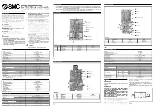
022a/engThis manual should be read in conjunction with the current valve catalogueSafety InstructionsThese safety instructions are intended to prevent a hazardous situation<strong>and</strong>/or equipment damage. These instructions indicate the levelof potential hazard by label of “Caution”, “Warning” or “Danger”.To ensure safety, be sure to observe ISO4414 (Note1) , JIS B 8370 (Note2)<strong>and</strong> other safety practices.Note 1: ISO 4414: Pneumatic fluid power – Recommendations for theapplication of equipment to transmission <strong>and</strong> control systems.Note 2: JIS B 8370: Pneumatic system axiom.CAUTION : Operator error could result in injury orequipment damage.WARNING: Operator error could result in seriousinjury or loss of life.DANGER : In extreme conditions, there is apossible result of serious injury or loss of life.WARNING1. The compatibility of pneumatic equipment is the responsibilityof the person who designs the pneumatic systemor decides its specifications.Since the products specified here are used in various operatingconditions, their compatibility for the specific pneumatic systemmust be based on specifications or after analysis <strong>and</strong>/or tests tomeet your specific requirements.St<strong>and</strong>ard specifications (Fig 1)<strong>Installation</strong> <strong>and</strong> <strong>Maintenance</strong> <strong>Manual</strong><strong>Series</strong> <strong>VT307</strong>/<strong>317</strong>/<strong>325</strong> Body Ported Solenoid ValveFor future reference, please keep this manual in a safe place2. Only trained personnel should operate pneumaticallyoperated machinery <strong>and</strong> equipment.Compressed air can be dangerous if an operator is unfamiliarwith it. Assembly, h<strong>and</strong>ling or repair of pneumatic systems shouldbe performed by trained <strong>and</strong> experienced operators.3. Do not service machinery/equipment or attempt toremove component until safety is confirmed.1) Inspection <strong>and</strong> maintenance of machinery/equipment shouldonly be performed after confirmation of safe locked-outcontrol positions.2) When equipment is to be removed, confirm the safety processas mentioned above. Switch off air <strong>and</strong> electrical supplies <strong>and</strong>exhaust all residual compressed air in the system.3) Before machinery/equipment is re-started, ensure all safetymeasures to prevent sudden movement of cylinders etc.(Bleed air into the system gradually to create back-pressure,i.e. incorporate a soft-start valve).4. Contact <strong>SMC</strong> if the product is to be used in any of thefollowing conditions:1) Conditions <strong>and</strong> environments beyond the given specifications,or if product is used outdoors.2) <strong>Installation</strong>s in conjunction with atomic energy, railway, airnavigation, vehicles, medical equipment, food <strong>and</strong> beverage,recreation equipment, emergency stop circuits, pressapplications, or safety equipment.3) An application which has the possibility of having negativeeffects on people, property, or animals, requiring specialsafety analysis.CAUTIONEnsure that the air supply system is filtered to 5 micron.FluidsAirOperating pressure range*No freezing 0~0.9 MPaAmbient <strong>and</strong> fluid temperature0~50°CResponse timeNote 1)Max. 20ms (at 0.5 MPa)Max. operating frequency10HzLubricationNot required<strong>Manual</strong> overrideNon-locking type, Push-turn-locking typeMounting positionFreeImpact/vibration resistanceNote 2)150/50 m/s 2 )EnclosureIP65*V, W type: -101.2kPa~0.1Solenoid specificationsElectrical entryDIN terminalVoltagesAC ( 50 / 60 Hz) 100, 200, 24, 48, 110, 220, 240DC 24, 6, 12, 48Voltage allowance-15%~+10% of rated voltageInsulationClass BApparent powerACInrush*12.7VA (50Hz) 10.7VA (60Hz)Holding*7.6VA (50Hz) 5.4VA (60Hz)Power consumption DC **4.8WLamp/surge AC ZNR (varister) neon lampProtection circuit DC Diode, LED* E type: Inrush: 7.9 (50), 6.2 (60), Holding: 5.8 (50), 3.5 (60)** E, Y, W type: 2, with lamp 2.2St<strong>and</strong>ard specifications (Fig 2)FluidAir, inert gasOperating pressure range* No freezing 0~0.9 MPaAmbient <strong>and</strong> fluid temperature0~50°CResponse timeNote 1)Max. 30ms (at 0.5MPa)Max. operating frequency10HzLubricationNot required<strong>Manual</strong> overrideNon-locking typeMounting positionFreeImpact/vibration resistanceNote 2)150/50 m/s 2 )EnclosureIP65*V, W type: -101.2kPa~0.1Solenoid specificationsElectrical entryDIN terminalVoltagesA/C ( 50 / 60 Hz) 100, 200, 24, 48, 110, 220, 240DC 24, 6, 12, 48Voltage allowance-15%~+10% of rated voltageInsulationClass BApparent powerACInrush19VA (50Hz) 16VA (60Hz)Holding11VA (50Hz) 7VA (60Hz)Power consumption DC 6W with lampLamp/surge voltage AC ZNR (varister) neon lampprotection circuit DC ZNR (varister), LEDSpecification (cont)* Note 1) : According to dynamic performance test JIS B8375-1981 (Coil temperature 20°C, at rated voltage, without surge voltage suppressor.)* * Note 2) : Shock resistance: No malfunction from test using drop impact tester, to axis <strong>and</strong> right angle direction of main valve <strong>and</strong> armature,each one time when energised <strong>and</strong> de-energised.Vibration resistance: No malfunction from test with 8.3 to 2000Hz 1 sweep, to axis <strong>and</strong> right angle direction of main valve <strong>and</strong>armature, each one time when energised <strong>and</strong> de-energised. (Value in the initial stage.)VT Sectioned viewMain partsFig 1VT<strong>317</strong> Sectioned viewMain partsFig 2 ArmatureMolded coilMovable pole piecePush rodBody Spool valve Return springNo. Description Material Notes Body Aluminum die-cast Metallic paint Spool valve Aluminum·NBR Return spring Stainless steel Molded coil Epoxy resin ArmatureMolded coilMovable pole piecePush rodBody Spool valve Return springNo. Description Material Notes Body Aluminum die-cast Metallic paint Spool valve Aluminum·NBR Return spring Stainless steel Molded coil Epoxy resinVT<strong>325</strong> Sectioned viewMain partsFig 3St<strong>and</strong>ard specifications (Fig 3)FluidsAir, inert gasOperating pressure range* 0~1 MPaAmbient <strong>and</strong> fluid temperature range5~50°CMax. operating frequency5 HzResponse timeNote 1)Max. 30ms (at 0.5 MPa)LubricationNot required<strong>Manual</strong> overrideNon-locking type, Locking typeMounting positionFreeImpact/vibration resistanceNote 2)150/50 m/s 2 )EnclosureIP65*V type: -101.2kPa~0.1 MPaSolenoid specificationsElectrical entryDIN terminalVoltagesAC ( 50 / 60 Hz) 100, 200, 110, 220, 240DC 24, 12Voltage allowance-15%~+10% of rated voltageInsulationClass BApparent powerACInrush50Hz75VA60Hz60VAHolding50Hz27VA60Hz17VAPower consumption DC 12WLamp/surge voltage AC ZNR (varister) neon lampProtection circuit DC ZNR (varister) LED<strong>Installation</strong>No. Description Material Notes Body ADC Metallic paint Cover ADC Metallic paint Spool valve A2017, NBRCAUTIONEnsure all air <strong>and</strong> power supplies are isolated before commencinginstallationWARNINGIT IS POSSIBLE TO INSTALL THESE VALVES IN THE OPEN ORCLOSED POSITION THEREFORE PAY CAREFUL ATTENTION TOTHE FOLLOWING INFORMATION:NORMALLY CLOSED MEANS THAT THERE IS NO OUTPUT FROMPORT 'A' WHEN PRESSURE IS CONNECTED TO PORT 'P' ANDTHE SOLENOID IS DE-ENERGISED.NORMALLY OPEN MEANS THAT THERE IS AN OUTPUT FROMPORT 'A' WHEN PRESSURE IS CONNECTED TO PORT 'R' ANDTHE SOLENOID IS DE-ENERGISEDIf the valve is required to operate in the Normally Closed position, theair pressure is connected to the port marked 'P' <strong>and</strong> the exhausting airexits from the port marked 'R'. Port 'A' is the output.If the valve is required to operate in the Normally Open position, theair pressure is connected to the port marked 'R' <strong>and</strong> the exhausting airexits from the port marked 'P'.DO NOT INSTALL THESE VALVES IN EXPLOSIVE ATMOSPHERESIf these valves are exposed to water or oil droplets, ensure that thevalves are protectedIf it is intended to energise a valve for extended periods please consult<strong>SMC</strong>.SymbolFig 10(A) 2(R) 3 Plunger Cover Coil Over travel assembly Body Spool valve O-ring Spool-spring Retainer1 (P)
CoilCoilCoilCoilCoilCoilTube connection (push-in fittings)1. Ensure that the end of the tube is cut square.2. Push the tube firmly into the fitting until it stops.3. Pull back on the tube to ensure that it is securely gripped.4. To disconnect the tube push down on the collet <strong>and</strong> holddown. Withdraw the tube from the fitting <strong>and</strong> release colletwhen the tube is removed. Collet Guide Collar Tube retainer TubeElectrical connection (DIN <strong>and</strong> terminal <strong>VT307</strong>)DIN terminal with lamp <strong>and</strong> surge protection have built in wiringconnections. Connect as per Fig 4.Fig 4Electrical connection (VT<strong>317</strong>)VT<strong>317</strong> series has 90° incremental positioning. Change electrical entryposition as follows. Loosen nut , remove coil from the bodyassembly , put positioning pin into required place, replace coil <strong>and</strong> secure nut .Fig 5Ground Tube seal Body O-ring StudTerminal No. 1 2DIN terminal + ––Terminal + ––VT<strong>317</strong>, VT<strong>325</strong> have no polarityDIN terminal with plateApplicable cable dia: ø4.5~ø7Applicable crimping terminal: 0.Y terminal (1.25-3)LubricationThese valves have been lubricated for life at manufacture <strong>and</strong> requireno additional lubrication.CAUTIONHowever, if a lubricant is to be used, a turbine oil type #1 (ISO VG32)should be used. If a lubricant is used, continuous lubrication must becarried out as the original lubricant will be washed away.WARNING<strong>Manual</strong> override operationExercise extreme CAUTION when operating a solenoid manual overrideas connected equipment will commence operation. Ensure allsafety measures are in place.Non-Locking push type (all valves)1. Push down on the manual override button (moulded black rubber)until it stops.2. Hold this position for the duration of the check. (ON position).3. Release the button <strong>and</strong> the override will re-set to the OFFposition.Push-Locking slotted type (VT<strong>325</strong>)To lock1. Insert a small bladed screwdriver into the slot <strong>and</strong> push downuntil it stops.2. Turn the override 90° left or right depending upon which optionis required (normally open or normally closed) until it stops.3. Remove the screwdriver.WARNINGIn this position the manual override is in the locked 'ON' position.To unlock1. Insert a small bladed screwdriver into the slot of the manual override.2. Turn the screwdriver 90° in the reverse direction.3. Remove the screwdriver <strong>and</strong> the manual override will re-set to theOFF position.CAUTIONThe design of the VT series (V type) valves are such that they may beused for vacuum applications.However, <strong>VT307</strong> (V) <strong>and</strong> VT<strong>317</strong> (V) VT<strong>325</strong> (V) must not be used as avacuum holding valve.If any valve is used in a dusty environment a filter should be insertedin the exhaust port <strong>and</strong> if a suction pad is used the filter should beinstalled between the pad <strong>and</strong> the valve.CAUTIONLeakage voltage (Fig 6)Please note, if a C-R element is used for contact protection, pleaseallow for an increase of leakage voltage which may pass through theC-R element.Contact points*Fig 6C-R elementValveLeakage voltageLeakage currentPowersupply* Please take note that non-contact relays sometimes have built-incurrent protection.The percentage of leakage voltage that remains on the coil after deenergizationshould be kept under 15% (<strong>VT307</strong>) or 20% (VT<strong>317</strong>) or15% (VT<strong>325</strong>) in the case of an AC coil, <strong>and</strong> under 3% (<strong>VT307</strong>) or 2%(VT <strong>317</strong>) or 2% (VT<strong>325</strong>) in the case of a DC coil, of the rated voltage.Surge voltage suppressionLamp/Surge voltage protection circuitAC48VDC or lessFig 7ACDCFig 8ACDCFig 9Terminal No. 1 (+)Fittings tightening torqueTerminal No. 2 (-)Terminal No. 1 (+)In case ofassemblyTerminal No. 2 (-)ZNR With surge voltage protection circuitZNRLEDIn case of assemblyIn case of lamp assemblyLEDZNRThread Tightening torque N-m (kgf/cm)1/8 7-9 (70-90)1/4 12-14 (120-140)3/8 22-24 (220-240)Using DIN connector with the series <strong>VT307</strong> (Fig 10)Disassembly1) Loosen screw <strong>and</strong> pull housing directly upward to removeconnector from the device (such as solenoid).2) Remove screw from housing <strong>and</strong> retain.3) Notch indicated by an arrow is at the bottom of terminal block. Insert screwdriver in the clearance between housing <strong>and</strong>terminal block , <strong>and</strong> pry housing off to remove terminalblock . Refer to Fig 10.4) Remove cable ground , <strong>and</strong> take out washer <strong>and</strong> rubberpacking .Wiring1) Pass cable ground , washer <strong>and</strong> rubber packing throughcable <strong>and</strong> insert into housing .2) Peel off a correct length of the coating of cable as shown inFig 10 <strong>and</strong> connect the cable end with crimp-style terminal .3) Remove screw (or loosen Y-shaped terminal) from terminalblock , mount crimp-style terminal to terminal block <strong>and</strong>tighten screw securely.Note: Tighten screw with torque range of 5 kgf/cm+/-15%.Remarksa) Wiring can be carried out with bare cables. If so, loosen screw(with washer) , insert lead wires in bracket <strong>and</strong> tighten thescrew.b) maximum outer diameter of cable should range from ø4.5mmto ø7.0mm.c) Applicable crimp-style terminals are shown in the table.Assembly1) Pass parts through cable as follows: cable ground , washer, rubber packing <strong>and</strong> housing . Connect cable to terminalblock . Then press terminal block into housing untilit clicks in place.2) Insert parts into the cable inlet of housing as follows: rubberpacking <strong>and</strong> washer , <strong>and</strong> tighten cable ground securely.3) Place gasket between the bottom part of terminal block <strong>and</strong> plug or device. Insert <strong>and</strong> tighten screw over the housing.Note: Tighten screw with torque range of 5 kgf/cm+/-20%.Remark: Connector orientation can be changed through an angle of180 degrees depending on the assembly of housing <strong>and</strong> terminalblock .Using DIN connector with series VT<strong>317</strong>, VT<strong>325</strong> (Fig 11)Disassembly1) Loosen screw <strong>and</strong> pull housing directly upward to removeconnector from the device (such as solenoid).2) Remove screw <strong>and</strong> remove gasket a or b.3) Notch (a) indicated by an arrow at the bottom of terminal block. Insert screwdriver into the clearance at the bottom, <strong>and</strong> lifthousing off to remove terminal block . Refer to the correctfigure.4) Remove cable ground , remove washer <strong>and</strong> rubber packing.Wiring1) Pass cable ground , washer <strong>and</strong> rubber packing throughcable <strong>and</strong> insert these into housing .2) Peel the coating of cable to the dimension shown in the figurebelow <strong>and</strong> connect the cable end with crimp-style terminal .3) Remove screw with washer e (or loosen Y-shaped terminal)from terminal block , mount crimp-style terminal to terminalblock <strong>and</strong> tighten screw e securely.Note: Tighten screw with torque range of 5 kgf/cm+/-15%.Remarks:a) Wiring can be carried out with bare cables. If so, loosen screwwith washer e, put lead wires in bracket d <strong>and</strong> tighten thescrew again.b) Maximum size of crimp-style terminal should be as follows:O-shaped terminal: 3.5 for lead wire of 1.25mm 2 sectional areaY-shaped terminal: 4 for lead wire of 1.25mm 2 sectional areac) Cables with outer diameters ranging from ø6mm to ø12mmcan be used.Note: For outer diameters between ø9mm <strong>and</strong> ø12mm, remove innerpart of rubber packing before use.Assembly1) Press terminal block into housing until it clicks in place.2) Place parts into the cable inlet of housing as follows: rubberpacking , washer <strong>and</strong> cable ground <strong>and</strong> tighten securely.3) Place gasket a or b between the bottom part of terminalblock <strong>and</strong> the plug on device. Insert <strong>and</strong> tighten screw overthe housing .Note: Tighten screw with torque range of 5 kgf/cm+/-20%.WARNING<strong>Maintenance</strong>UNDER NO CIRCUMSTANCES ATTEMPT TO CHANGE THESOLENOID AS THIS IS AN INTEGRAL PART OF THE VALVE ANDDOING SO WILL NEGATE ANY SUCH <strong>SMC</strong> WARRANTY.When you enquire about the product, please contact the following<strong>SMC</strong> Corporation:ENGLAND Phone 01908-563888 TURKEY Phone 212-2211512ITALY Phone 02-92711 GERMANY Phone 6103-402-0HOLLAND Phone 020-5318888 FRANCE Phone 01-64-76-10-00SWITZERLAND Phone 052-34-0022 SWEDEN Phone 08-603 07 00SPAIN Phone 945-184100 AUSTRIA Phone 02262-62-280Phone 902-255255 IRELAND Phone 01-4501822GREECE Phone 01-3426076 DENMARK Phone 8738-0800FINLAND Phone 09-68 10 21 NORWAY Phone 67-12 90 20BELGIUM Phone 03-3551464 POLAND Phone 48-22-6131847<strong>VT307</strong>Fig 10VT<strong>317</strong>/<strong>325</strong>Fig 11baSelf-tightening screwEnlarged view