

MK-MK2 Rotary clamp cylinder.. - SMC Pneumatics (Ireland)
MK-MK2 Rotary clamp cylinder.. - SMC Pneumatics (Ireland)
MK-MK2 Rotary clamp cylinder.. - SMC Pneumatics (Ireland)
- No tags were found...

Create successful ePaper yourself
Turn your PDF publications into a flip-book with our unique Google optimized e-Paper software.
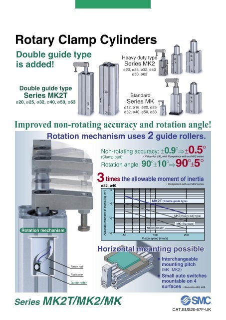
Series <strong>MK</strong>/<strong>MK</strong>2/<strong>MK</strong>2TModel SelectionItemSeries <strong>MK</strong> <strong>MK</strong>2 <strong>MK</strong>2Tø12, ø16200——Max. piston speed Note) [mm/s] ø20, ø25180200ø32 to ø63ø12±1.4°200——ø16±1.2°——Non-rotationg accuracy(Clamp part)ø20, ø25±1.2°±1.0°ø32, ø40ø50, ø63±0.9°±0.7°±0.5°±0.5°Rotation angleHorizontal mounting90°±10°Not allowed90°±5°AllowedNote) “Maximum piston speed” indicates the maximum speed possible when employing a standard arm.During un<strong>clamp</strong>ing(Extension end)CounterclockwiseDuring un<strong>clamp</strong>ing(Extension end)ClockwiseRotation angleRotation angleDuring <strong>clamp</strong>ing (Retraction end)Non-rotating accuracy[Actual calculation example]AL SB1.0 x 10 –1Bore size ø32, ø40<strong>MK</strong>2TArm: Ι1Arm weight: m1Clamp jig: Ι2Clamp jig weight: m2øDExample) Find the moment of inertia of the arm.AΙ1 = m1 · 2 + B 22A+ m1 · – S122Find the moment of inertia of the <strong>clamp</strong> jig.D 2Ι2 = m2 · + m2 · L82Allowable moment of inertia [kg·m 2 ]1.0 x 10 –21.0 x 10 –34.6 x 10 –4<strong>MK</strong>2<strong>MK</strong>Ι (Moment of inertia)(Calculation example) Cylinder bore size ø32A = 0.07 m, B = 0.02 m, S = 0.012 m, L = 0.045 m, D = 0.02 mm1 = 0.16 kg, m2 = 0.15 kg0.07Ι1 = 0.16 x 2 + 0.02 220.07+ 0.16 x – 0.012 = 1.6 x 10 –4 kg·m12220.02Ι2 = 0.15 x 2+ 0.15 x 0.045 2 = 3.0 x 10 –4 kg·m82Find the actual moment of inertia.Ι = Ι1 + Ι2 = (1.6 + 3.0) x 10 –4 = 4.6 x 10 –4 kg·m 2Front matter 11.0 x 10 –4 10 100 120 200Maximum piston speed [mm/s]Calculation Example (ø32, <strong>clamp</strong> stroke 10 mm)Series<strong>MK</strong><strong>MK</strong>2Max. piston speed120 mm/s200 mm/sAverage piston speed Note 1) Stroke total75 mm/s125 mm/s25 mmNote 1) Average piston speed = Maximum piston speed ÷ 1.6.Note 2) Please use the stroke speeds indicated above.1000Stroke time Note 2)0.35 sec.0.2 sec.
Model SelectionMoment of Inertiaø12, ø16ø20, ø25<strong>MK</strong>10 –2<strong>MK</strong>2TAllowable moment of inertia [kg·m 2 ]10 –410 –510 –3 50 100 200ø16 Standard arm single unitAllowable moment of inertia [kg·m 2 ]10 –310 –1 50 100 200<strong>MK</strong>2<strong>MK</strong>10 –4ø20, ø25 Standard arm single unitø12 Standard arm single unit10 –610 –5Maximum piston speed [mm/s]Maximum piston speed [mm/s]ø32, ø40ø50, ø63<strong>MK</strong>2T<strong>MK</strong>2T<strong>MK</strong>2Allowable moment of inertia [kg·m 2 ]10 –210 –310 –1 50 100 200<strong>MK</strong>2<strong>MK</strong>Allowable moment of inertia [kg·m 2 ]10 –210 –310 –1 <strong>MK</strong>50 100 200ø50, ø63 Standard arm single unitø32, ø40 Standard arm single unit10 –410 –4Maximum piston speed [mm/s]Maximum piston speed [mm/s]Note) Maximum piston speed is equivalent to approximately 1.6x the average piston speed. (Rough indication)Front matter 2
<strong>Rotary</strong> Clamp Cylinder: StandardSeries <strong>MK</strong>ø12, ø16, ø20, ø25, ø32, ø40, ø50, ø63<strong>Rotary</strong> <strong>clamp</strong> <strong>cylinder</strong>StandardMounting bracketSymbol MountingApplicable bore size (mm)BThrough-hole/Both endstapped common (Standard)ø12, ø16A Both ends tappedB Through-holeø20 to ø63G Head end flange∗ Head end flange is equipped with a boss mounting. Be sure to specifybody option “F”.∗ Mounting bracket is included, (but not assembled).1216202512 mm16 mm20 mm25 mmBore size32 32 mm40 40 mm50 50 mm63 63 mmSymbol102050How to Order<strong>MK</strong> A 20 10—TNTFPort thread typeM thread ø12 to ø25RcNPT ø32 to ø63GClamp stroke10 mm20 mm50 mmClamp strokeApplicable bore sizeø12 to ø40ø12 to ø63ø50 to ø63Applicable Auto Switches/Refer to page 29 through 39 for further information on auto switches.TypeSpecial functionDiagnostic indication(2-colour indication)Water resistant(2-colour indication)ElectricalentryGrommetConnectorGrommetYesYesGrommetWiring(Output)3-wire (NPN)3-wire (PNP)2-wire3-wire (NPN)3-wire (PNP)2-wire3-wire (NPN)3-wire (PNP)2-wire4-wire2-wire (No polarity)3-wire(NPN equivalent)Load voltageDC AC5 V,12 V12 V5 V,24 V12 V12 V—5 V,12 V12 V5 V, 12 V——5V —No2-wireYesConnectorNo24 VDiagnostic indication(2-colour indication) Grommet Yes∗ Lead wire length symbols: 0.5 m ·········· — (Example) M9NW1 m ·········· M (Example) M9NWM3 m ·········· L (Example) M9NWL5 m ·········· Z (Example) M9NWZNone ·········· N (Example) J79CN200 V100 V100 V or less—24 V or less—RF—MFN—SAuto switch typeNumber of auto switches2 pcs.1 pc.— Without auto switch (Built-in magnet)∗ For applicable auto switch models, refer to the table below.Body optionStandard (Female thread)Rod end width across flats ∗With boss on head end ∗With arm∗ Regarding body option manufacturable range, refer to the table below.Body Option Manufacturable RangeBore sizeø12, ø16ø20 to ø63—M—F—NMF—FN—∗ Arms are assembled at the time of shipment.<strong>Rotary</strong> direction(Un<strong>clamp</strong> → Clamp)RLAuto switch modelPerpendicular In-lineM9BWClockwiseCounterclockwiseø12, ø16 ø20 to ø63 ø12, ø16 ø20 to ø63M9NM9PM9B—M9NWM9PWM9BWM9NAM9PAM9BALead wire length (m)∗ Solid state switches marked with “” are produced upon receipt of order.∗ For D-P4DW, ø40 to ø63 are available.∗ Only D-P4DW type is assembled at the time of shipment.Made to Order(Refer to page 2 and 40.)∗ Since there are other applicable auto switches than listed, refer to page 18 for details.∗ For details about auto switches with pre-wired connector, refer to the “Best <strong>Pneumatics</strong>” catalogue.∗ When mounting models D-M9(V), M9W(V), M9A(V), and A9(V) with between ø32 and ø50 on sides other than the port side, please order a switch mounting bracketseparately as per the instructions on page 17, and refer to cases CDQP2B32 to 100 in Information (04-E514) “Cylinder with Compact Auto Switch.”∗ Auto switches are included, (but not assembled).1Reed switch Solid state switchDiagnostic output(2-colour indication)Magnetic field resistant(2-colour indication)Indicator light—12 V5 V, 12 V12 V5 V, 12 V—M9NVM9PVM9BV— J79CM9NWVM9PWVM9BWVM9NAVM9PAVM9BAV——A96V— A72A93VA90V— A73C— A80C— A79W——A96F79FP4DW— A72HA93A90———0.5(—)—1(M)—————————————3(L)5 None(Z) (N)—————————————————————Pre-wiredconnector————————ApplicableloadIC circuit—IC circuit—IC circuit—IC circuit—IC circuit—IC circuit—IC circuit—Relay,PLC—Relay,PLC
<strong>Rotary</strong> Clamp Cylinder: Standard Series <strong>MK</strong>Specifications<strong>Rotary</strong> AngleDuring un<strong>clamp</strong>ing(Extension end)80° to 100°(90°±10°)L typeSymbolXB6Option/ArmBore size (mm)1216202532405063Made to Order(For details, refer to page 40.)DescriptionHead resistant <strong>cylinder</strong> (150°C)During un<strong>clamp</strong>ing(Extension end)80° to 100°(90°±10°)R typeClamp partNon-rotating accuracy±0.7° to 1.4°During <strong>clamp</strong>ing (Retraction end)Part no.<strong>MK</strong>-A012<strong>MK</strong>-A016<strong>MK</strong>-A020<strong>MK</strong>-A032<strong>MK</strong>-A050AccessoriesClamp bolt,Hexagon sockethead cap screw,Hexagon nut,Spring washerMounting Bracket/FlangeBore size (mm)202532405063Part no.<strong>MK</strong>-F020<strong>MK</strong>-F025<strong>MK</strong>-F032<strong>MK</strong>-F040<strong>MK</strong>-F050<strong>MK</strong>-F063AccessoriesCenteringlocation ring,Set pin,Bolt for <strong>cylinder</strong>bodyBore size (mm)ActionNote 1)Rotation angleNote 2)<strong>Rotary</strong> direction<strong>Rotary</strong> stroke (mm)Clamp stroke (mm)Theoretical <strong>clamp</strong> force (N)FluidProof pressureOperating pressure rangeNote 3)Ambient and fluid temperatureLubricationPiping port sizeMountingCushionStroke length tolerancePiston speedNote 1)Non-rotating accuracy (Clamp part)12 16 20 25 32 40 50 63Double acting90° ±10°Clockwise, Counterclockwise7.5 9.5 15 1910, 20 20, 5040 75 100 185 300 525 825 1400Air1.5 MPa0.1 to 1 MPaWithout auto switch: –10 to 70°C (No freezing)With auto switch: –10 to 60°C (No freezing)Non-lubeM5 x 0.8Rc1/8, NPT1/8, G1/8 Rc1/4, NPT1/4, G1/4Through-hole/Bothends tapped commonBoth ends tapped, Through-hole, Head end flangeRubber bumper+0.6–0.450 to 200 mm/s±1.4° ±1.2° ±0.9° ±0.7°Note 1) Refer to “<strong>Rotary</strong> Angle” figure.Note 2) Direction of rotation viewed from the rod end when the piston rod is retracting.Note 3) At 0.5 MPa.Theoretical OutputBore size(mm)1216202532405063Rod size(mm)68121216162020OperatingdirectionRHRHRHRHRHRHRHRHPiston area(cm 2 )0.81.11.52233.74.96810.512.516.519.62831.20.32433456060.890.2112149182243319380502596851948Note) Theoretical output (N) = Pressure (MPa) x Piston area (cm 2 ) x 100Weight/Through-hole MountingClamp stroke(mm)102050127087—Additional WeightBore size (mm)Both ends tappedRod end width across flatsWith boss on head endWith armHead end flange(including mounting bolt)12———13—16100123—16———32—Calculation: (Example) <strong>MK</strong>G20-10RFN• Standard calculation: <strong>MK</strong>B20-10R• Extra weight calculation: Both ends tappedHead end flangeWith boss on head endWith arm20250290—206102100133250 g6 g133 g2 g100 g491 gOperating pressure (MPa)0.5 0.740 5655 7775 105100 140100 139149 208185 258245 341300 418400 557525 731625 870825 1149980 13651400 19501560 2172Bore size (mm)25 32280 500320 525— —257103100153327215200166Unit: N1.080110150200200298370490600800105012501648196128013121Operating directionR: Rod end (Clamp)H: Head end (Un<strong>clamp</strong>)40595640—40621720019850—110013505074613350345Unit: g63—15201805Unit: g631746253505312
Series <strong>MK</strong>Construction<strong>MK</strong>12, 16 <strong>MK</strong>20, 25@3With arm (N)!6!7!5!8!9<strong>MK</strong>32y !2 @4 o@7 r i !1 t q @6 u !0 @5 w eRod end width across flats (M)yWith boss on head end (F)@0@8Name plate<strong>MK</strong>40 to 63!4@1 @2Head end flange (G)Component PartsNo.1234567891011121314DescriptionRod coverCylinder tubePistonBushingGuide pinPiston rodBumperRing nutScraper pressureMagnetHexagon socket head set screwRound R-type retaining ringParallel pinC-type retaining ringMaterialAluminium alloyAluminium alloyAluminium alloyCopper bearing materialStainless steelStainless steelCarbon steelUrethaneCopper alloyStainless steel—Chromium molybdenum steelSpring steelStainless steelCarbon tool steelNoteHard anodisedHard anodisedø32 to ø63 onlyNitridedø12 to ø25 Nitridedø32 to ø63 Heated, Nickel platedø20 to ø32 onlyExcept ø12, ø16Sharp end section: 90°Used at ø12, ø16, ø32 to ø63Component PartsNo.1516171819202122232425262728DescriptionArmClamp boltHexagon nutHexagon socket head cap screwSpring washerCentering location ringFlangeHexagon sockethead cap screwSpacer for switch typeCoil scraperPiston sealGasketRod sealO-ringMaterialRolled steelChromium molybdenum steelRolled steelChromium molybdenum steelHard steelAluminum alloyRolled steelChromiummolybdenum steelAluminum alloyPhosphor bronzeNBRNBRNBRNBR!3NoteExcept ø12, ø16Except ø12, ø16ø20, ø25: 2Qty.ø32 to ø63: 4ø12, ø16 onlyExcept ø12, ø16Replacement Parts: Seal KitBore size (mm)Kit no.Contentø12<strong>MK</strong>-12-PSø16<strong>MK</strong>-16-PSø20 to ø32ø40Not able to disassemble <strong>MK</strong>-40-PSSet of nos. above @4 @5 @6 @7 @8∗ Seal kit includes @4 to @8. Order the seal kit, basing on each bore size (except ø20 to ø32).3ø50<strong>MK</strong>-50-PSø63<strong>MK</strong>-63-PS
<strong>Rotary</strong> Clamp Cylinder: Standard Series <strong>MK</strong>PrecautionsBe sure to read this before handling.Refer to back page 1 for Safety Instructionsand “Precautions for Handling PneumaticDevices” (M-03-E3A) for Common Precautions.Precautions for Designing and Mounting ArmsWhen arms are to be made separately, their length and weight should be within the followingrange.1. Allowable bending momentUse the arm length and operating pressure in Graph (1) to select an allowable bendingmoment loaded piston rod.CautionClamp Arm Mounting1. Use a <strong>clamp</strong> arm that is available as an option.To fabricate a <strong>clamp</strong> arm, make sure that theallowable bending moment and the inertialmoment are within the specified range.If a <strong>clamp</strong> arm that exceeds the specified valueis installed, the internal mechanism in the<strong>cylinder</strong> could become damaged.Ensuring Safety1. If one side of the piston is pressurised bysupplying air with the <strong>clamp</strong> arm attached, thepiston will move vertically while the <strong>clamp</strong> armrotates. This operation could be hazardous topersonnel, as their hands or feet could getcaught by the <strong>clamp</strong> arm, or could lead toequipment damage. Therefore, it is importantto secure as a danger zone a cylindrical areawith the length of the <strong>clamp</strong> arm as its radius,and the stroke plus 20 mm as its height.Installation and Adjustment/Clamp Arm Removal and Reinstallation1. During the removal or reinstallation of the<strong>clamp</strong> arm, make sure to use a wrench or avise to secure the <strong>clamp</strong> arm before removingor tightening the bolt.This is to prevent the bolt tightening torquefrom being applied to the piston rod, whichcould damage the <strong>cylinder</strong>’s internal mecha-Mounting Bolt for <strong>MK</strong>BMounting: Mounting bolt for through-hole type isavailable.Ordering: Add the word “<strong>MK</strong>B” to the mountingbolt size.Example) M5 x 75 L (<strong>MK</strong>B)Mounting boltGraph (1)<strong>MK</strong>50/63Arm length l (cm)Moment of inertia (kg·m 2 )<strong>MK</strong>32/40<strong>MK</strong>20/25<strong>MK</strong>16Operatingrange2. Moment of inertiaWhen the arm is long and heavy, damage of internal parts may be caused due to inertia.Use the inertia moment and <strong>cylinder</strong> speed in Graph (2) basing on the arm requirements.Graph (2)Operating pressure (MPa)<strong>MK</strong>50/63<strong>MK</strong>32/40<strong>MK</strong>20/25<strong>MK</strong>12/16When the arm length is 8 cm, pressure shouldbe less than<strong>MK</strong>20/25: 0.45 MPa<strong>MK</strong>32/40: 0.55 MPa<strong>MK</strong>50/63: 0.8 MPa.When the arm’s moment of inertia is 3 x 10 –4kg·m 2 , the <strong>cylinder</strong> speed should be less than<strong>MK</strong>20/25: 65 mm/s<strong>MK</strong>32/40: 150 mm/s.For calculating the moment of inertia, refer tofront matter 1, 2, back page 8.Note) The maximum piston speed is equivalentto approximately 1.6x the averagepiston speed. (Rough indication)FlatwasherNote) Be sure to use a flat washer to mountø12 and ø16 <strong>cylinder</strong>s via through-holes.OperatingrangeCylinder model C D8888<strong>MK</strong>B12-10<strong>MK</strong>B12-20<strong>MK</strong>B16-10<strong>MK</strong>B16-20<strong>MK</strong>B20-10<strong>MK</strong>B20-20<strong>MK</strong>B25-10<strong>MK</strong>B25-20<strong>MK</strong>B32-10<strong>MK</strong>B32-20<strong>MK</strong>B40-10<strong>MK</strong>B40-20<strong>MK</strong>B50-20<strong>MK</strong>B50-50<strong>MK</strong>B63-20<strong>MK</strong>B63-5010910.576.511.510.550605060758575858595758595130100130Mounting bolt sizeM3 x 50 LM3 x 60 LM3 x 50 LM3 x 60 LM5 x 75 LM5 x 85 LM5 x 75 LM5 x 85 LM5 x 85 LM5 x 95 LM5 x 75 LM5 x 85 LM6 x 95 LM6 x 130 LM8 x 100 LM8 x 130 LNote) Maximum piston speed (mm/s)• To attach and detach the arm to and from thepiston rod, fix the arm with a wrench or viseand then tighten the bolt.(If an excessive force is applied in the rotarydirection, it may cause damage to the internalmechanism.)Refer to the following table for the tighteningtorque for mounting.(N·m)Bore size (mm) Proper tightening torque120.4 to 0.6162 to 2.420, 254 to 632, 408 to 1050, 6314 to 16WrenchHexagonwrenchkeyArm4
USeries <strong>MK</strong>Dimensions: ø12, ø16, ø20, ø25Through-hole (Basic): <strong>MK</strong>B2 x M5Flat washer4 pcs.4 x ø3.5ø12Auto switchMinimum bending radiusof lead wire 10ø16øBE effective thread depth F2 x 4 x M4Effective depth 7DøGH9øHModel<strong>MK</strong>B12<strong>MK</strong>B1635.5 + Clamp stroke48 + 2 x Clamp stroke(mm)A B C D E F G H025 32 15.5 5 M3 5.5 11h9 –0.043 6029 38 20 7 M5 6.5 14h9 –0.043 8CA2 x 4 x ø6.5Counterbore depth 4Model M<strong>MK</strong>B12-N 18.5<strong>MK</strong>B16-N 21.5N811O2936P2025Q45RM3M4(mm)S81112With arm: <strong>MK</strong> 16 -NNM + Clamp strokeQOP8 to 18SR threadø20, ø25FELø12øOh92 x M5(Piping port)–0.110–0.225M8Effective threaddepth 11K+0.152 x ø3.3 +0.05 depth 33 S5.54 3 R + Clamp strokeCBKL2 x ø5.5 through2 x 2 x ø9counterbore depth 7Q + 2 x Clamp strokeBoth ends tapped: <strong>MK</strong>AM6A1010R + Clamp stroke(Basic)Model A B C E F K L Oh9 Q0<strong>MK</strong>B20 36 46.8 36 49 25.5±0.15±0.1513.5 7.5 20 –0.0520<strong>MK</strong>B25 40 52 40 54.5 28.5 16±0.158±0.1523 –0.05272.573.5Note) Dimension when the rod is extended is to be added to the <strong>clamp</strong> stroke plus rotary stroke.R6263S3132(mm)U455
ø<strong>Rotary</strong> Clamp Cylinder: Standard Series <strong>MK</strong>Head end flange: <strong>MK</strong>G+0.152 x ø6.3+0.05With boss on head end2 x ø6.62 x M6(Special cap bolt)DCR + Clamp strokeModel<strong>MK</strong>G20<strong>MK</strong>G25B6064C3942D25.528±0.1±0.14852(mm)E±0.15±0.15Model<strong>MK</strong>20-F<strong>MK</strong>25-F(mm)Ah913150–0.0430–0.04342.5 + Clamp strokeøEB20With arm: <strong>MK</strong> 25-N22 + Clamp stroke20Rod end width across flats: <strong>MK</strong> 25 -M2 x ø5.212 to 22M66
Series <strong>MK</strong>Dimensions: ø32, ø40, ø50, ø63Through-hole (Basic): <strong>MK</strong>BKøYh92 x VMinimum lead wirebending radius 10Auto switchøB+0.152 x ø3.3 +0.05 depth 3øUOCLI thread effectivedepth JL(ø3.3)5.5ZXSR + Clamp strokeQ + 2 x Clamp strokeT4 x øG through2 x 4 x øHcounterboreDCAKPBoth ends tapped: <strong>MK</strong>AR + Clamp stroke(Basic)Model32<strong>MK</strong>A 40<strong>MK</strong>A50<strong>MK</strong>A63AM6M8M10(mm)B101418Model<strong>MK</strong>B32<strong>MK</strong>B40<strong>MK</strong>B50<strong>MK</strong>B63A B C D G H I J K L M N O P Q R S T U455264776069861033440506014141717–0.1–0.2–0.1–0.2–0.1–0.2–0.1–0.25.5 9 depth 75.5 9 depth 76.6 11 depth 89 14 depth 10.5M10M10M12M1212 2012 2415 3015 35Note 1) Figures above are for D-M9, M9W, M9A, A9.Note 2) Dimension when the rod is extended is to be added to the <strong>clamp</strong> stroke plus rotary stroke.±0.15±0.15±0.15±0.157789±0.15±0.15±0.15±0.15M6M8M101014 4.5 93.5 71.5 3714 5 94.5 65 29.5141819197711211576.58034357.5 168 1610.5 2010.5 20(mm)V— TN TF X Yh9 Z0Rc1/8 NPT1/8 G1/8 3 30 –0.062 6.50Rc1/8 NPT1/8 G1/8 3 30 –0.062 6.50Rc1/4 NPT1/4 G1/4 3.5 37–0.0627.50Rc1/4 NPT1/4 G1/4 3.5 48 –0.062 7.57
<strong>Rotary</strong> Clamp Cylinder: Standard Series <strong>MK</strong>Head end flange: <strong>MK</strong>G+0.152 x ø6.3+0.05With boss on head end4 x G(Special cap bolt)EBøAh9DC4 x øFR + Clamp strokeAModel<strong>MK</strong>G32<strong>MK</strong>G40<strong>MK</strong>G50<strong>MK</strong>G63A8899B657289108C48546780(mm)D E F G34405060±0.1±0.1±0.1±0.156627692±0.15±0.15±0.15±0.155.5 M65.5 M66.6 M89 M10Model<strong>MK</strong>32-F<strong>MK</strong>40-F50<strong>MK</strong> -F63(mm)Ah92128350–0.0520–0.0520–0.062With armF + Clamp strokeARod end width across flatsC + Clamp strokeDF EBDøB A2 x øGGCHModel<strong>MK</strong>32-N<strong>MK</strong>40-N<strong>MK</strong>50-N<strong>MK</strong>63-NA18182222B67678888C20202222D45456565F G35.515 to 25435330 to 4052.5(mm)HM8M8M10M10Model<strong>MK</strong>32-M<strong>MK</strong>40-M<strong>MK</strong>50-M<strong>MK</strong>63-MA6688B14141818C53.5617776.5D36364646E18182323(mm)F G9 6.29 6.211.5 8.211.5 8.28
<strong>Rotary</strong> Clamp Cylinder: Heavy Duty TypeSeries <strong>MK</strong>2ø20, ø25, ø32, ø40, ø50, ø63How to OrderBG<strong>MK</strong>2 B 20 10<strong>Rotary</strong> <strong>clamp</strong> <strong>cylinder</strong>Heavy duty typeMounting bracketThrough-hole/Both ends tapped common (Standard)Head end flange∗ Head end flange is equipped with a boss mounting. Be sure tospecify body option “F”.∗ Mounting bracket is included, (but not assembled).202532Symbol10205020 mm25 mm32 mm—TNTFBore size40 40 mm50 50 mm63 63 mmPort thread typeM thread ø20, ø25RcNPT ø32 to ø63GClamp stroke10 mm20 mm50 mmClamp strokeApplicable bore sizeø20 to ø40ø20 to ø63ø50 to ø63RFBody option—FNNumber of auto switches—S2 pcs.1 pc.Auto switch type— Without auto switch (Built-in magnet)∗ For applicable auto switch models, refer to the tablebelow.Standard (Female thread)With boss on head endWith arm∗ Arms are assembled at the time of shipment.<strong>Rotary</strong> direction(Un<strong>clamp</strong> → Clamp)RLClockwiseCounterclockwiseM9BWApplicable Auto Switches/Refer to page 29 through 39 for further information on auto switches.TypeReed switch Solid state switchSpecial functionDiagnostic indication(2-colour indication)Water resistant(2-colour indication)Diagnostic output(2-colour indication)Magnetic field resistant(2-colour indication)Diagnostic indication(2-colour indication)ElectricalentryGrommetConnector2-wire12 V3-wire (NPN) 5 V,3-wire (PNP) 12 VYes24 V2-wire12 V—Grommet 3-wire (NPN) 5 V,3-wire (PNP) 12 V2-wire12 V4-wire5 V, 12 V2-wire (No polarity)—3-wire5 V —(NPN equivalent) —GrommetYesConnectorIndicator lightNoYesNoYesGrommet∗ Lead wire length symbols: 0.5 m ·········· —Wiring(Output)3-wire (NPN)3-wire (PNP)2-wire24 VLoad voltageDC(Example) M9NW1 m ·········· M (Example) M9NWM3 m ·········· L (Example) M9NWL5 m ·········· Z (Example) M9NWZNone ·········· N (Example) J79CN5 V,12 VAC— 200 V12 V 100 V5 V, 12 V 100 V or less12 V —5 V, 12 V 24 V or less— —Auto switch modelPerpendicularIn-lineø20 to ø32 ø40 to ø63M9NVM9NM9PVM9PM9BVM9BJ79C—M9NWV M9NWM9PWV M9PWM9BWV M9BWM9NAV M9NAM9PAV M9PAM9BAV M9BA—F79F— — P4DWA96VA72A93VA90VA73CA80CA79WA96A72HA93A90———Lead wire length (m)0.5(—)—1(M)—————————————3(L)5 None(Z) (N)—————∗ Solid state switches marked with “” are produced upon receipt of order.∗ For D-P4DW, ø40 to ø63 are available.∗ Only D-P4DW type is assembled at the time of shipment.————————————————Pre-wiredconnector————————ApplicableloadIC circuit—IC circuit—IC circuit—IC circuit—IC circuit—IC circuit—IC circuit—∗ Since there are other applicable auto switches than listed, refer to page 18 for details.∗ For details about auto switches with pre-wired connector, refer to the “Best <strong>Pneumatics</strong>” catalogue .∗ When mounting models D-M9(V), M9W(V), M9A(V), and A9(V) with between ø32 and ø50 on sides other than the port side, please order a switch mounting bracketseparately as per the instructions on page 17, and refer to cases CDQP2B32 to 100 in Information (04-E514) “Cylinder with Compact Auto Switch.”∗ Auto switches are included, (but not assembled).9Relay,PLC—Relay,PLC
<strong>Rotary</strong> Clamp Cylinder: Heavy Duty Type Series <strong>MK</strong>2SpecificationsBore size (mm)ActionNote 1)Rotation angleNote 2)<strong>Rotary</strong> direction<strong>Rotary</strong> stroke (mm)Clamp stroke (mm)Theoretical <strong>clamp</strong> force (N)FluidProof pressureOperating pressure rangeNote 3)Ambient and fluid temperatureLubricationPiping port sizeMountingCushionStroke length tolerancePiston speedNon-rotating accuracy (Clamp part)20 25 32 40 50 63Double acting90° ±10°Clockwise, Counterclockwise9.5 15 1910, 2020, 50100 185 300 525 825 1400Air1.5 MPa0.1 to 1 MPaWithout auto switch: –10 to 70°C (No freezing)With auto switch: –10 to 60°C (No freezing)Non-lubeM5 x 0.8 Rc1/8, NPT1/8, G1/8 Rc1/4, NPT1/4, G1/4Through-hole/Both ends tapped common, Head end flangeRubber bumper+0.6–0.450 to 200 mm/s±1.2° ±0.9° ±0.7°Note 1) Refer to the “<strong>Rotary</strong> Angle” figure.Note 2) Direction of rotation viewed from the rod end when the piston rod is retracting.Note 3) At 0.5 MPa.<strong>Rotary</strong> AngleDuring un<strong>clamp</strong>ing(Extension end)80° to 100°(90°±10°)L typeOption/ArmBore size (mm)202532405063Bore size (mm)202532405063During un<strong>clamp</strong>ing(Extension end)80° to 100°(90°±10°)R typeClamp partNon-rotating accuracy±0.7° to 1.2°During <strong>clamp</strong>ing (Retraction end)Part no.<strong>MK</strong>-A020<strong>MK</strong>-A032<strong>MK</strong>-A050Mounting Bracket/FlangePart no.<strong>MK</strong>2-F020<strong>MK</strong>2-F025<strong>MK</strong>2-F032<strong>MK</strong>2-F040<strong>MK</strong>2-F050<strong>MK</strong>2-F063AccessoriesClamp bolt,Hexagon sockethead cap screw,Hexagon nut,Spring washerAccessoriesCenteringlocation ring,Set pin,Bolt for <strong>cylinder</strong>bodyTheoretical OutputUnit: NBore size Rod size Operating Piston areaOperating pressure (MPa)(mm) (mm) direction (cm 2 ) 0.3 0.5 0.7 1.0202532405063121216162020RRRRRR23.7610.516.52860.8112182319502851100185300525825140013925841873111491950200370600105016482801HHHHHH34.9812.519.631.290.2149243380596948149245400625980156020834155787013652172298490800125019613121Note) Theoretical output (N) = Pressure (MPa) x Piston area (cm 2 ) x 100Operating directionR: Rod end (Clamp)H: Head end (Un<strong>clamp</strong>)Weight/Through-hole MountingClamp stroke(mm) 20102602030050—Additional Weight25295335—Bore size (mm)With boss on head endWith armHead end flange (including mounting bolt)Calculation: (Example) <strong>MK</strong>2G20-10RFN• Standard calculation: <strong>MK</strong>2B20-10R• Extra weight calculation: Head end flangeWith boss on head endWith arm202100133260 g133 g2 g100 g495 gBore size (mm)32 40353 635555 680— —25310015332520016640720019850—117014205013350345Unit: g63—16201890Unit: g632535053110
Series <strong>MK</strong>2Construction<strong>MK</strong>220, 25With arm (N)!6!7!5!8!9<strong>MK</strong>232With boss on head end (F)y !2 @4 o @7 r i !1 t q @6 u !0 @5 w e@0@3!3 @9 #0<strong>MK</strong>240 to 63!4Head end flange (G)@1 @2@8Component PartsNo.123456789101112131415DescriptionRod coverCylinder tubePistonBushingGuide pinPiston rodBumperRing nutScraper pressureMagnetHexagon socket head set screwRound R-type retaining ringName plateC-type retaining ringArmMaterialAluminium alloyAluminium alloyAluminium alloyCopper bearing materialStainless steelStainless steelCarbon steelUrethaneCopper alloyStainless steel—Chromium molybdenum steelSpring steelAluminiumCarbon tool steelRolled steelNoteø32 to ø63 onlyNitridedø20, ø25 Nitridedø32 to ø63 Heated, Nickel platedø20 to ø32 onlySharp end section: 90°ø40 to ø63 onlyComponent PartsNo.161718192021222324252627282930DescriptionClamp boltHexagon nutHexagon socket head cap screwSpring washerCentering location ringFlangeHexagon sockethead cap screwO-ringCoil scraperPiston sealGasketRod sealParallel pinWear ringBumper BMaterialChromium molybdenum steelRolled steelChromium molybdenum steelHard steelAluminium alloyRolled steelChromiummolybdenum steelNBRPhosphor bronzeNBRNBRNBRStainless steelResinUrethaneQty.Noteø20, ø25: 2ø32 to ø63: 4Replacement Parts: Seal KitBore size (mm)Kit no.Content20 25Not able to disassemble32 40<strong>MK</strong>2-40-PSSet of nos. above @3 @4 @5 @6 @7∗ Seal kit includes @3 to @7. Order the seal kit, basing on each bore size.1150<strong>MK</strong>2-50-PS63<strong>MK</strong>2-63-PS
<strong>Rotary</strong> Clamp Cylinder: Heavy Duty Type Series <strong>MK</strong>2PrecautionsBe sure to read this before handling.Refer to back page 1 for Safety Instructionsand “Precautions for Handling PneumaticDevices” (M-03-E3A) for Common Precautions.CautionClamp Arm Mounting1. Use a <strong>clamp</strong> arm that is available as an option.To fabricate a <strong>clamp</strong> arm, make sure that theallowable bending moment and the inertialmoment are within the specified range.If a <strong>clamp</strong> arm that exceeds the specified valueis installed, the internal mechanism in the<strong>cylinder</strong> could become damaged.Ensuring Safety1. If one side of the piston is pressurised bysupplying air with the <strong>clamp</strong> arm attached, thepiston will move vertically while the <strong>clamp</strong> armrotates. This operation could be hazardous topersonnel, as their hands or feet could getcaught by the <strong>clamp</strong> arm, or could lead toequipment damage. Therefore, it is importantto secure as a danger zone a cylindrical areawith the length of the <strong>clamp</strong> arm as its radius,and the stroke plus 20 mm as its height.Installation and Adjustment/Clamp Arm Removal and Reinstallation1. During the removal or reinstallation of the<strong>clamp</strong> arm, make sure to use a wrench or avise to secure the <strong>clamp</strong> arm before removingor tightening the bolt.This is to prevent the bolt tightening torquefrom being applied to the piston rod, whichcould damage the <strong>cylinder</strong>’s internal mecha-Mounting Bolt for <strong>MK</strong>2BMounting: Mounting bolt for through-hole type isavailable.Ordering: Add the word “<strong>MK</strong>2B” to the mountingbolt size.Example) M5 x 75 L (<strong>MK</strong>2B)FlatwasherMounting boltArm length l (cm)20108642Precautions for Designing and Mounting ArmsWhen arms are to be made separately, their length and weight should be within the followingrange.1. Allowable bending momentUse the arm length and operating pressure in Graph (1) to select an allowable bendingmoment loaded piston rod.Graph (1)<strong>MK</strong>250/63<strong>MK</strong>232/40<strong>MK</strong>220/25Operatingrange0.45 0.55 0.80.1 0.2 0.4 0.6 1Operating pressure (MPa)2. Moment of inertiaWhen the arm is long and heavy, damage of internal parts may be caused due to inertia.Use the inertia moment and <strong>cylinder</strong> speed in Graph (2) basing on the arm requirements.Graph (2)Moment of inertia (kg·m 2 )3 <strong>MK</strong>250/63210 –264210 –3642<strong>MK</strong>232/40<strong>MK</strong>220/25OperatingrangeWhen the arm length is 8 cm, pressure shouldbe less than<strong>MK</strong>220/25: 0.45 MPa<strong>MK</strong>232/40: 0.55 MPa<strong>MK</strong>250/63: 0.8 MPa.When the arm’s moment of inertia is 5 x 10 –3kg·m 2 , the <strong>cylinder</strong> speed should be less than<strong>MK</strong>232/40: 66 mm/s<strong>MK</strong>250/63: 120 mm/s.For calculating the moment of inertia, refer tofront matter 1, 2, back page 8.Note) The maximum piston speed is equivalentto approximately 1.6x the averagepiston speed. (Rough indication)lCylinder model<strong>MK</strong>2B20-10<strong>MK</strong>2B20-20<strong>MK</strong>2B25-10<strong>MK</strong>2B25-20<strong>MK</strong>2B32-10<strong>MK</strong>2B32-20<strong>MK</strong>2B40-10<strong>MK</strong>2B40-20<strong>MK</strong>2B50-20<strong>MK</strong>2B50-50<strong>MK</strong>2B63-20<strong>MK</strong>2B63-50Note) Be sure to use a flat washer to mount<strong>cylinder</strong>s via through-holes.C8.510.510610.510.59D75858090901008090105135105135Mounting bolt sizeM5 x 75 LM5 x 85 LM5 x 80 LM5 x 90 LM5 x 90 LM5 x 100 LM5 x 80 LM5 x 90 LM6 x 105 LM6 x 135 LM8 x 105 LM8 x 135 L10 –466 12050 100 200Note) Maximum piston speed (mm/s)• To attach and detach the arm to and from thepiston rod, fix the arm with a wrench or viseand then tighten the bolt.(If an excessive force is applied in the rotarydirection, it may cause damage to the internalmechanism.)Refer to the following table for the tighteningtorque for mounting.Bore size (mm)20, 2532, 4050, 63(N·m)Proper tightening torque4 to 68 to 1014 to 16WrenchHexagonwrenchkeyArm12
LSeries <strong>MK</strong>2Dimensions: ø20, ø25+0.152 x ø6.3+0.052 x ø6.62 x M6 (Special cap bolt)24.5 + Clamp strokeøAh9DACBJ + Clamp stroke12 to 22M6Head End FlangeModel<strong>MK</strong>2G20<strong>MK</strong>2G25A6064B3942C25.528±0.1±0.1(mm)D4852±0.15±0.15With armWith Boss onHead EndModel<strong>MK</strong>220-F<strong>MK</strong>225-F(mm)øAh9013 –0.043015 –0.043DEGøHh92 x M5–0.110–0.225ø12M8Effective threaddepth 11F+0.152 x ø3.3 +0.05 depth 317M63 K5.5(ø5.5)4 3 J + Clamp strokeCBFG2 x ø5.5 through2 x 2 x ø9counterbore depth 7I + 2 x Clamp strokeAThrough-hole/Both Ends Tapped Common (Standard) (mm)Model A B C D E F G øHh9 I J K L0<strong>MK</strong>2B20 36 46.8 36 49 25.5 13.5±0.157.5±0.1520 –0.0520<strong>MK</strong>2B25 40 52 40 54.5 28.5 16±0.158±0.1523 –0.05275.578.562.565.5313245Note) Dimension when the rod is extended is to be added to the <strong>clamp</strong> stroke plusrotary stroke.13
<strong>Rotary</strong> Clamp Cylinder: Heavy Duty Type Series <strong>MK</strong>2Dimensions: ø32, ø40, ø50, ø634 x G(Special cap bolt)+0.152 x ø6.3+0.05E + Clamp strokeHead End FlangeModel A B C<strong>MK</strong>2G32 8 65 48<strong>MK</strong>2G40 8 72 54<strong>MK</strong>2G50 9 89 67<strong>MK</strong>2G63 9 108 8034405060D±0.1±0.1±0.1±0.156627692E±0.15±0.15±0.15±0.15øF5.55.56.69(mm)GM6M6M8M10With ArmModel A<strong>MK</strong>232-N 18<strong>MK</strong>240-N 18<strong>MK</strong>250-N 22<strong>MK</strong>263-N 22B67678888C20202222D45456565E39465857.5F15 to 2530 to 40(mm)GM8M8M10M10KNote) The figures below illustrate auto switches D-M9, M9W,M9A, and A9.øYh92 x 4 x N2 x 4 x MWith Boss onHead EndModel<strong>MK</strong>232-F<strong>MK</strong>240-F50<strong>MK</strong>2 -FøB(mm)øAh9021 –0.052028 –0.052035 –0.062+0.152 x ø3.3 +0.05 depth 3LøULOCBDEBDC4 x øFR + Clamp strokeFCGøAh9Minimum bending radiusof lead wire 10Auto switch2 x V63I thread length J(ø3.3)5.5ZXSR + Clamp strokeQ + 2 x Clamp strokeT4 x øG through2 x 4 x øHcounterboreDCAKPThrough-hole/Both Ends Tapped Common (Standard)Model A B C D E F øG øH I JM<strong>MK</strong>2B32<strong>MK</strong>2B40<strong>MK</strong>2B50<strong>MK</strong>2B63455264776069861033440506014141717–0.1–0.2–0.1–0.2–0.1–0.2–0.1–0.254 31.5 5.5 9 depth 7617335415.5 9 depth 76.6 11 depth 886 47.5 9 14 depth 10.5M10M10M12M12Note 1) The <strong>cylinder</strong> rod is retracted.Note 2) <strong>Rotary</strong> direction is viewed from the rod end when the piston rod is retracting.Note 3) Dimension when the rod is extended is to be added to the <strong>clamp</strong> stroke plus rotary stroke.(mm)K L N O P Q R S T øUV— TN TFX øYh9 Z12 20±0.157±0.150M6 17 14 4.5 101.5 76 37 7.5 16 Rc1/8 NPT1/8 G1/8 3 30 –0.062 6.5012 24±0.157±0.15 M6 17 14 5 102.5 70 29.5 8 16 Rc1/8 NPT1/8 G1/8 3 30 –0.062 6.515 30±0.158±0.150M8 22 19 7 122 81.5 34 10.5 20 Rc1/4 NPT1/4 G1/4 3.5 37 –0.062 7.515 35±0.159±0.150M10 28.5 19 7 125 85 35 10.5 20 Rc1/4 NPT1/4 G1/4 3.5 48 –0.062 7.514
Series <strong>MK</strong>/<strong>MK</strong>2Auto Switch Proper Mounting Position (Detection at Stroke End) and its Mounting HeightApplicable Cylinders: <strong>MK</strong> Seriesø12ø16When mountedWhen mounteda) b)a) b)D-M9D-M9WD-M9ALD-A9D-M9VD-M9WVD-M9AVLD-A9V≈≈Auto Switch Proper Mounting Position (mm)Auto switchmodelBore size12A11.5D-M9/M9VD-M9W/M9WVD-M9AL/M9AVLB4.5W5.5A7.5D-A9D-A9VB0W1.5 (4)Auto Switch Mounting Height (mm)Auto switchmodelBore size1216D-M9VD-M9WVD-M9AVLHs1921D-A9VHs1719161246802 (4.5)Note 1) ( ): D-A93Note 2) Size W is suitable for mounting models D-M9, D-M9W, D-M9AL, and D-A9.Note 3) When setting an auto switch, confirm the operation and adjust its mounting position.15
<strong>Rotary</strong> Clamp Cylinder Series <strong>MK</strong>/<strong>MK</strong>2Auto Switch Proper Mounting Position (Detection at Stroke End) and its Mounting HeightApplicable Cylinders: <strong>MK</strong>, <strong>MK</strong>2 SeriesD-M9D-M9VD-M9WD-M9WVD-M9ALD-M9AVLD-A9D-A9Vø20, ø25ABø32 to ø63 ø20, ø25 ø32 to ø63Auto Switch Proper Mounting PositionApplicable Cylinders: <strong>MK</strong> SeriesAuto switchmodelBore size202532405063D-M9D-M9VD-M9WVD-M9WD-M9ALD-M9AVLA B30 7.530.5 835.5 926.5 11.531 14.531.5 17.5D-A9D-A9VA2626.531.522.52727.5B3.5457.510.513.5A28.52932.523.52828.5D-A73D-A80B66.568.511.514.5D-A72/A7HD-A80H/A73CD-A80C/F7/F79FD-J79/F7V/J79CD-F7BA/F7WD-J79W/F7WVA B29 6.529.5 733 6.524 928.5 1229 15D-F7NTLA B34 11.534.5 1238 11.529 1433.5 1734 20D-A79WA B26 3.526.5 430 3.521 625.5 926 12D-P4DWLA B— —— —— —19.5 4.524 7.524.5 10.5Note) When setting an auto switch, confirm the operation and adjust its mounting position.Auto Switch Proper Mounting PositionApplicable Cylinders: <strong>MK</strong>2 SeriesAuto switchmodelBore size202532405063D-M9D-M9VD-M9WD-M9WVD-M9ALD-M9AVLA B30 831 1036 1327 1631 19.531.5 22.5D-A9D-A9VA262732232727.5B4691215.518.5A28.529.533242828.5D-A73D-A80B6.58.5101316.519.5D-A72/A7HD-A80H/A73CD-A80C/F7/F79FD-J79/F7V/J79CD-F7BA/F7WD-J79W/F7WVA B29 730 933.5 10.524.5 13.528.5 1729 20D-F7NTLA B34 1234.5 1438 15.529 18.533.5 2234 25D-A79WA B26 427 630.5 7.521.5 10.525.5 1426 17D-P4DWLA B— —— —— —20 924 12.524.5 15.5Note) When setting an auto switch, confirm the operation and adjust its mounting position.Operating RangeAuto switch modelD-M9/M9VD-M9W/M9WVD-M9AL/M9AVLD-A9/A9VD-F7/J79D-F7V/J79CD-F7W/F7WVD-J79WD-F79F/F7BALD-F7BAVL/F7NTLD-A7/A80D-A7H/A80HD-A73C/A80CD-A79WD-P4DWLBore size12 16 20 25 32 40 50 63232.543.54.53.5546.545.546.556.567.510109.59.59.511.5— — 5.5 5 6 6 6 6.5— — 12 12 12 11 10 12— — 13 13 13 14 14 16— — — — — 5 5 5(mm)∗ This is a guideline including hysteresis, not meant to be guaranteed.(Assuming approximately ±30% dispersion.)There may be the case it would vary substantially dependingon an ambient environment.∗ Figures for models D-M9(V), M9W(V), M9A(V)L, andA9(V) with ø12 or ø16 (<strong>MK</strong>), or ø32 or more (<strong>MK</strong>, <strong>MK</strong>2),indicate the operating range when using the existing switchmountinggroove, without using switch mounting bracket BQ2-012.16
Series <strong>MK</strong>/<strong>MK</strong>2Auto Switch Mounting Bracket/Part No.Auto switchmountingsurfaceBore size (mm)ø12, ø16 ø20, ø25 ø32, ø40, ø50 ø63Port sidePort sidePort sideCACACAAuto switchmodelD-M9D-M9VD-M9WD-M9WVD-M9ALD-M9AVLD-A9D-A9VBAuto switch mounting surfaceA, B, C sideNo auto switch mountingbracket necessary.Auto switch mounting surfaceOnly on auto switch mounting rail sideqBQ-1wBQ2-012Two types of auto switch mountingbracket are used as a set.qwSet screw(not used)BAuto switch mounting surfacePort sideA, B, C sideqBQ-2wBQ2-012Two types of auto switch mountingbracket are used as a set.No autoswitchmountingbracketnecessary.qwSet screw(not used)BAuto switch mounting surfacePort, A, B, C sideNo auto switch mountingbracket necessary.Note 1) For ø32 to ø50 of each <strong>cylinder</strong> series, when mounting compact auto switches on one of the three sides other than the port side (above A, B, C side) in the figure above, aseparate auto switch mounting bracket is necessary as shown in the table above, so please order one separately from the <strong>cylinder</strong>.(Same case when mounting compact auto switches with the auto switch mounting rail, not using the compact auto switch mounting groove, for diameters ø63 to ø100.)Example<strong>MK</strong>A32-10R-M9BW ····· 1 unitBQ-2 ····· 2 pcs.BQ2-012 ····· 2 pcs.Note 2) When the <strong>cylinder</strong> is shipped, an auto switch mounting bracket and an auto switch are included.Bore size (mm)Auto switch model20 25 32 40 50 63D-F7/J79D-F7VD-J79CD-F7W/J79WD-F7WVD-F7BAL/F7BAVLD-F79F/F7NTLD-A7/A80D-A73C/A80CD-A7H/A80HD-A79WBQ-1BQ-2D-P4DWL— BQP1-050Note) When the <strong>cylinder</strong> is shipped, an auto switch mounting bracket and an auto switch are included.However, ø40 to ø63 with the D-P4DWL are assembled at the time of shipment.[Mounting screws set made of stainless steel]The set of stainless steel mounting screws (with nuts) described below is available and can be used depending onthe operating environment. (Please order the auto switch spacer BQ-2, since it is not included.)The “D-F7BAL/F7BAVL” switch is set on the <strong>cylinder</strong> with the stainless steel screws above when shipped.When only a switch is shipped independently, the “BBA2” screw set is attached.Detailed Contents of the Stainless Steel Mounting Screw SetPartContentno.Description Size Qty.M3 x 8 l 1Auto switch mounting screwM3 x 10 l 1BBA2Auto switch mounting nut (Square nut) M3 1Auto switch mounting nut (Convex type) M3 1Applicable autoswitch mountingbracket part no.BQ-1BQ-2BQ-1BQ-2Applicableauto switchD-A7D-A8D-F7D-J7Note) When using BQ-1, BBA2 may be used by itself.When using BQ-2, BQ-2 and BBA2 should be used together as a set, and used in combination with the spacer (blackresin material) and stainless steel screws.17Auto Switch MountingBracket WeightMounting bracket part no.BQ-1BQ-2BQ2-012BQP1-050Weight (g)1.51.5516
<strong>Rotary</strong> Clamp Cylinder Series <strong>MK</strong>/<strong>MK</strong>2The following auto switches are applicable to other models than those listed in the "How to Order" section.For detailed specifications, refer to the “Best <strong>Pneumatics</strong>” catalogue.Type Model Electrical entryFeaturesSolid state switchD-F7NV, F7PV, F7BVD-F7NWV, F7BWVD-F7BAVLD-F79, F7P, J79D-F79W, F7PW, J79WD-F7BALD-F7NTLD-P4DWLGrommet (Perpendicular)Grommet (In-line)D-A73—Grommet (Perpendicular)D-A80Without indicator lightReed switchD-A73H, A76H—Grommet (In-line)D-A80HWithout indicator light∗ Pre-wired connectors are also available for solid state switches. For details, refer to the “Best <strong>Pneumatics</strong>” catalogue.∗ Normally closed (NC = b contact), solid state switches (D-F9G/F9H type) are also available. For details, refer to the “Best <strong>Pneumatics</strong>”catalogue.∗ The D-A7, A8, F7, and J7 cannot be mounted to ø12 and ø16 models.—Diagnostic indication (2-colour indication)Water resistant—Diagnostic indication (2-colour indication)Water resistant (2-colour indication)With timerMagnetic field resistant18
<strong>Rotary</strong> Clamp Cylinder: Double Guide TypeSeries <strong>MK</strong>2Tø20, ø25, ø32, ø40, ø50, ø63How to OrderBG<strong>Rotary</strong> <strong>clamp</strong> <strong>cylinder</strong>Double guide type∗ Mounting bracket is included, (but not assembled).<strong>MK</strong>2T B 20 10Mounting bracketThrough-hole/Both ends tapped common (Standard)Head end flange—TNTFSymbol10205020253220 mm25 mm32 mmClamp stroke10 mm20 mm50 mmBore size40 40 mm50 50 mm63 63 mmCylinder portM thread ø20, ø25RcNPT ø32 to ø63GClamp strokeApplicable bore sizeø20 to ø40ø20 to ø63ø50 to ø63RNBody option—NM9BWNumber of auto switches—S2 pcs.1 pc.Auto switch type— Without auto switch (Built-in magnet)∗ For applicable auto switch models, refer to the tablebelow.Standard (Female thread)With arm∗ Arms are included when shipped, (butnot assembled).<strong>Rotary</strong> direction(Un<strong>clamp</strong> → Clamp)RLClockwiseCounterclockwiseMade to Order(Refer to page 20 and 40.)Applicable Auto Switches/Refer to page 29 through 39 for further information on auto switches.TypeReed switch Solid state switchSpecial functionElectricalentryConnectorNoYesNoYesGrommet∗ Lead wire length symbols: 0.5 m ·········· —Wiring(Output)3-wire(NPN equivalent)YesGrommet2-wireLoad voltage∗ Since there are other applicable auto switches than listed, refer to page 26 for details.∗ For details about auto switches with pre-wired connector, refer to page the “Best <strong>Pneumatics</strong>” catalogue.∗ Auto switches are included, (but not assembled).19Diagnostic indication(2-colour indication)Water resistant(2-colour indication)Diagnostic output(2-colour indication)Magnetic field resistant(2-colour indication)Diagnostic indication(2-colour indication)GrommetConnectorGrommetIndicator lightYes3-wire (NPN)3-wire (PNP)2-wire3-wire (NPN)3-wire (PNP)2-wire3-wire (NPN)3-wire (PNP)2-wire4-wire2-wire (No polarity)—24 VDC(Example) M9NW1 m ·········· M (Example) M9NWM3 m ·········· L (Example) M9NWL5 m ·········· Z (Example) M9NWZNone ·········· N (Example) J79CN5 V,12 V12 V5 V—12 V5 V, 12 V12 V5 V, 12 V—AC24 V5 V,12 V12 V5 V,12 V12 V5 V, 12 V———200 V100V100 V or less—24 V or less—Auto switch modelDirect mounting Rail mountingø20 to ø63 ø32 to ø63Perpendicular In-line Perpendicular In-lineM9NVM9PVM9BV—M9NWVM9PWVM9BWVM9NAVM9PAVM9BAV——A96V—A93VA90V———M9NM9PM9B—M9NWM9PWM9BWM9NAM9PAM9BA——A96—A93A90——————J79C—————————A72——A73CA80CA79W——————————F79FP4DW—A72H—————Lead wire length (m)0.5(—)—1(M)—————————————3(L)5 None(Z) (N)—————∗ Solid state switches marked with “” are produced upon receipt of order.∗ For D-P4DW, ø40 to ø63 are available.∗ Only D-P4DW type is assembled at the time of shipment.————————————————Pre-wiredconnector————————ApplicableloadIC circuit—IC circuit—IC circuit—IC circuit—IC circuit—IC circuit—IC circuit—Relay,PLC—Relay,PLC
<strong>Rotary</strong> Clamp Cylinder: Double Guide Type Series <strong>MK</strong>2TSpecificationsBore size (mm)ActionNote 1)Rotation angleNote 2)<strong>Rotary</strong> direction<strong>Rotary</strong> stroke (mm)Clamp stroke (mm)Theoretical <strong>clamp</strong> force (N)FluidProof pressureOperating pressure rangeNote 3)Ambient and fluid temperatureLubricationPiping port sizeMountingCushionStroke length tolerancePiston speedNon-rotating accuracy (Clamp part)20 25 32 40 50 63Double acting90° ±5°Clockwise, Counterclockwise19 293310, 2020, 50100 185 300 525 825 1300Air1.5 MPa0.1 to 1 MPaWithout auto switch: –10 to 70°C (No freezing)With auto switch: –10 to 60°C (No freezing)Non-lubeM5 x 0.8 Rc1/8, NPT1/8, G1/8 Rc1/4, NPT1/4, G1/4Through-hole/Both ends tapped common, Head end flangeRubber bumper+1.0050 to 200 mm/s±1.0° ±0.5°Note 1) Refer to the “<strong>Rotary</strong> Angle” figure.Note 2) Direction of rotation viewed from the rod end when the piston rod is retracting.Note 3) At 0.5 MPa.<strong>Rotary</strong> AngleDuring un<strong>clamp</strong>ing(Extension end)85° to 95°(90°±5°)L typeSymbolX1859Option/ArmBore size (mm)202532405063Bore size (mm)202532405063During un<strong>clamp</strong>ing(Extension end)85° to 95°(90°±5°)R typeClamp partNon-rotating accuracy±0.5° to 1.0°During <strong>clamp</strong>ing (Retraction end)Made to Order(For details, refer to page 40.)DescriptionWith head end pin holePart no.<strong>MK</strong>-A020<strong>MK</strong>-A032<strong>MK</strong>-A050<strong>MK</strong>2T-A063Mounting Bracket/FlangePart no.CQS-F020CQS-F025<strong>MK</strong>2T-F032<strong>MK</strong>2T-F040<strong>MK</strong>2T-F050<strong>MK</strong>2T-F063AccessoriesClamp bolt,Hexagon sockethead cap screw,Hexagon nut,Spring washerAccessoriesHexagon sockethead cap screwTheoretical OutputUnit: NBore size Rod size Operating Piston areaOperating pressure (MPa)(mm) (mm) direction (cm 2 ) 0.3 0.5 0.7 1.0202532405063121216162025RRRRRR23.7610.516.52660.8112182319502780100185300525825130013925841873111491820200370600105016482600HHHHHH34.9812.519.631.290.2149243380596948149245400625980156020834155787013652172298490800125019613121Note) Theoretical output (N) = Pressure (MPa) x Piston area (cm 2 ) x 100Operating directionR: Rod end (Clamp)H: Head end (Un<strong>clamp</strong>)Weight/Through-hole MountingClamp stroke(mm) 20103672043350—Additional WeightBore size (mm)With armHead end flange (including mounting bolt)Calculation: (Example) <strong>MK</strong>2TG20-10RN• Standard calculation: <strong>MK</strong>2TB20-10R• Extra weight calculation: Head end flangeWith arm25448520—20100133367 g133 g100 g600 gBore size (mm)32 40806 1008914 1127— —25100153322001664020019850—2049267250350345Unit: g63—26093354Unit: g6360053120
Series <strong>MK</strong>2TConstruction<strong>MK</strong>2T20 to 63With arm (N)Head end flange (G)!4!5!3!7!6!8!6i @0@5!2!0@2!9rq wu y to !1@1@3eo!9 @5@4@6In case of <strong>clamp</strong> stroke 50 mmComponent PartsNo.123456789101112DescriptionRod coverCylinder tubePistonBushingGuide shaftGuide rollerRetaining ringPiston rodBumperSeal retainerMagnetKeyMaterialStructural steelAluminium alloyAluminium alloyOil-impregnated sintered alloyBronze castedStainless steelStructural steelStructural steelSteel for special applicationsStainless steelStructural steelUrethaneAluminium alloy—Structural steelNoteElectroless nickel platedAnodic oxide coatingTrivalent chromatedø20, ø25ø32 to ø63ø20, ø25: Hard chrome platedø32 to ø63: Hard chrome platedø20, ø25: Phosphate coatingø32 to ø63: Zinc trivalent chromatedø20, ø25: Hard chrome platedø32 to ø63: Hard chrome platedTrivalent chromatedZinc trivalent chromatedComponent PartsNo.1314151617181920212223242526DescriptionArmClamp boltHexagon nutHexagon socket head cap screwSpring washerFlangeGasketCoil scraperPiston sealRod sealWear ringBottom plateRetaining ringHexagon socket headcap screw (with SW)WasherHexagon socket head cap screwMaterialStructural steelStructural steelStructural steelStructural steelSteel wireStructural steelNBRBronzeNBRNBRResinAluminium alloySteel for special applicationsStructural steelStainless steelStructural steelNoteElectroless nickel platedElectroless nickel platedNickel platedNickel platedNickel platedNickel platedAnodic oxide coatingPhosphate coatingNickel plated(ø40 to ø63 only)ø25, ø32 onlyNickel plated (ø25, ø32 only)Replacement Parts: Seal KitBore size (mm)Kit no.Content20<strong>MK</strong>2T20-PS25<strong>MK</strong>2T25-PS32<strong>MK</strong>2T32-PS40<strong>MK</strong>2T40-PSSet of nos. above !9 @0 @1 @2∗ Seal kit includes !9, @0, @1, @2. Order the seal kit, basing on each bore size.2150<strong>MK</strong>2T50-PS63<strong>MK</strong>2T63-PS
<strong>Rotary</strong> Clamp Cylinder: Double Guide Type Series <strong>MK</strong>2TPrecautionsBe sure to read this before handling.Refer to back page 1 for Safety Instructionsand “Precautions for Handling PneumaticDevices” (M-03-E3A) for Common Precautions.CautionClamp Arm Mounting1. Use a <strong>clamp</strong> arm that is available as an option.To fabricate a <strong>clamp</strong> arm, make sure that theallowable bending moment and the inertialmoment are within the specified range.If a <strong>clamp</strong> arm that exceeds the specified valueis installed, the internal mechanism in the<strong>cylinder</strong> could become damaged.Ensuring Safety1. If one side of the piston is pressurised bysupplying air with the <strong>clamp</strong> arm attached, thepiston will move vertically while the <strong>clamp</strong> armrotates. This operation could be hazardous topersonnel, as their hands or feet could getcaught by the <strong>clamp</strong> arm, or could lead toequipment damage. Therefore, it is importantto secure as a danger zone a cylindrical areawith the length of the <strong>clamp</strong> arm as its radius,and the stroke plus 20 mm as its height.Installation and Adjustment/Clamp Arm Removal and Reinstallation1. During the removal or reinstallation of the<strong>clamp</strong> arm, make sure to use a wrench or avise to secure the <strong>clamp</strong> arm before removingor tightening the bolt.This is to prevent the bolt tightening torquefrom being applied to the piston rod, whichcould damage the <strong>cylinder</strong>’s internal mecha-Mounting Bolt for <strong>MK</strong>2TBMounting: Mounting bolt for through-hole type isavailable.Ordering: Add the word “<strong>MK</strong>2TB” to themounting bolt size.Example) M5 x 115 L (<strong>MK</strong>2TB) 4 pcs.Mounting boltFlatwasherNote) Be sure to use a flat washer to mount<strong>cylinder</strong>s via through-holes.Graph (1)<strong>MK</strong>2T50/6320<strong>MK</strong>2T32/40Arm length l (cm)108642Precautions for Designing and Mounting ArmsWhen arms are to be made separately, their length and weight should be within the followingrange.1. Allowable bending momentUse the arm length and operating pressure in Graph (1) to select an allowable bendingmoment loaded piston rod.<strong>MK</strong>2T20/25Operatingrange0.45 0.55 0.80.1 0.2 0.4 0.6 1Operating pressure (MPa)When the arm length is 8 cm, pressure shouldbe less than<strong>MK</strong>2T20/25: 0.45 MPa<strong>MK</strong>2T32/40: 0.55 MPa<strong>MK</strong>2T50/63: 0.8 MPa.2. Moment of inertiaWhen the arm is long and heavy, damage of internal parts may be caused due to inertia.Use the inertia moment and <strong>cylinder</strong> speed in Graph (2) basing on the arm requirements.Graph (2)Moment of inertia (kg·m 2 )10 –110 –210 –3<strong>MK</strong>2T50/63<strong>MK</strong>2T32/40<strong>MK</strong>2T20/25OperatingrangeWhen the arm’s moment of inertia is 1 x 10 –2kg·m 2 , the <strong>cylinder</strong> speed should be less than<strong>MK</strong>2T32/40: 85 mm/s<strong>MK</strong>2T50/63: 140 mm/s.For calculating the moment of inertia, refer tofront matter 1, 2, back page 8.Note) The maximum piston speed is equivalentto approximately 1.6x the averagepiston speed. (Rough indication)lCylinder model<strong>MK</strong>2TB20-10<strong>MK</strong>2TB20-20<strong>MK</strong>2TB25-10<strong>MK</strong>2TB25-20<strong>MK</strong>2TB32-10<strong>MK</strong>2TB32-20<strong>MK</strong>2TB40-10<strong>MK</strong>2TB40-20<strong>MK</strong>2TB50-20<strong>MK</strong>2TB50-50<strong>MK</strong>2TB63-20<strong>MK</strong>2TB63-50C11118.58.511.511.57.57.513.5101314D115135115135145165145165185245185250Mounting bolt sizeM5 x 115 LM5 x 135 LM5 x 115 LM5 x 135 LM5 x 145 LM5 x 165 LM5 x 145 LM5 x 165 LM6 x 185 LM6 x 245 LM8 x 185 LM8 x 250 L10 –450 85100140 200Note) Maximum piston speed (mm/s)• To attach and detach the arm to and from thepiston rod, fix the arm with a wrench or viseand then tighten the bolt.(If an excessive force is applied in the rotarydirection, it may cause damage to the internalmechanism.)Refer to the following table for the tighteningtorque for mounting.Bore size (mm)20, 2532, 405063(N·m)Proper tightening torque4 to 68 to 1014 to 16106 to 127WrenchHexagonwrenchkeyArm22
Series <strong>MK</strong>2TDimensions: ø20, ø252 x ø6.617.5145135711 to 2216 M6Head End FlangeModel<strong>MK</strong>2TG20<strong>MK</strong>2TG25A6064B3942(mm)C4852S2 x M55.5ø12CACAB8M8Thread length 11øB4 x ø5.4 through2 x 4 x ø9 counterbore depth 74.5172 x 4 x M6RQ1710 –0.07–0.15CA10 –0.07–0.15Through-hole/Both Ends Tapped Common (Standard)Bore size2025A øB C3640475225.528Clamp stroke 10 mmQ R S116.5119110.51135959Clamp stroke 20 mmQ R S136.5 130.5 69139 133 69(mm)23
EBACD<strong>Rotary</strong> Clamp Cylinder: Double Guide Type Series <strong>MK</strong>2TDimensions: ø32, ø40, ø50, ø634 x øFEABDDCA10FCGHead End FlangeModel A B<strong>MK</strong>2TG32 8<strong>MK</strong>2TG40 8<strong>MK</strong>2TG50 9<strong>MK</strong>2TG63 9657289108C48546780D34405060E56627692(mm)øF5.55.56.69With ArmModel<strong>MK</strong>2T32-N<strong>MK</strong>2T40-N<strong>MK</strong>2T50-N<strong>MK</strong>2T63-NA18182232B67678891C20202232D45456565E21.52129.534.5F15 to 2515 to 2520 to 4020 to 40(mm)GM8M8M10M10NS2 x 4 x M thread 2 x VNTI thread length JøUOøBKRQ4 x øG through2 x 4 x øH counterbore depthDCAPThrough-hole/Both Ends Tapped Common (Standard)Bore size A øB C D G H I J K M N O P øU324050634552647760698610334405060141417–0.07–0.15–0.07–0.15–0.07–0.1522 –0.07–0.155.55.56.699 depth 79 depth 711 depth 814 depth 10.5M10M10M12M16121215216678M6M6M8M1017172228.5141419194.557716162025(mm)VNil TN TFRc1/8 NPT1/8 G1/8Rc1/8 NPT1/8 G1/8Rc1/4 NPT1/4 G1/4Rc1/4 NPT1/4 G1/4Bore size32405063Clamp stroke 10 mmQ R S T148151.5——140144——7475——7.58——Clamp stroke 20 mmQ R S T168171.5191192160164179182848591.5937.5812.510.5Clamp stroke 50 mmQ R S T——254.5256——242.5246——121.5123——141524
Series <strong>MK</strong>2TAuto Switch Proper Mounting Position (Detection at Stroke End)ø20 to ø63ø32 to ø63Auto switch (Direct mounting)BAuto switch (Rail mounting)BAAMounting Rail mounting Direct mountingModel<strong>MK</strong>2T20<strong>MK</strong>2T25<strong>MK</strong>2T32<strong>MK</strong>2T40<strong>MK</strong>2T50-20st<strong>MK</strong>2T50-50st<strong>MK</strong>2T63-20st<strong>MK</strong>2T63-50stD-A7D-A8A——73 (73.5)74 (74.5)89.5 (90)119.5 (120)91.5 (92)121.5 (122)B——10.5 (11)13 (13.5)18.5 (19)22 (22.5)19.5 (20)23.5 (24)D-A7H/A80HD-A73C/A80CD-F7/F79F/J79D-F7V/J79CD-F7BA/F7WD-J79W/F7WVA B— —— —73.5 1174.5 13.590 19120 22.592 20122 24D-A79WA——70.571.58711789119B——810.51619.51721D-P4DWLA———7085.5115.587.5117.5∗ ( ): D-A72Note) When setting an auto switch, confirm the operation and adjust its mounting position.B———914.51815.519.5D-M9D-M9VD-M9WD-M9WVD-M9ALD-M9AVLA B60.5 961 1176 13.577 1692.5 21.5122.5 2594.5 22.5124.5 26.5D-A9D-A9VA56.557727388.5118.590.5120.5B579.51217.52118.522.5D-F7NTLA6363.578.579.59512597127B11.513.51618.52427.52529Operating RangeOperating Range (Dimensions) (mm)Auto switch model20 25Bore size32 40 50 63D-M9/M9V— — 4.5 4.5 5 5D-M9W/M9WVD-M9AL/M9AVL— — 6.5 5.5 6.5 6.5D-A9/A9V9 9.5 9 9.5 9.5 11D-F7/J79D-F7V/F79F/J79CD-F7W/F7WV— — 6 6 6 6.5D-F79F/F7BAL/F7BAVL/F7NTLD-A7/A80D-A7H/A80H— — 9.5 11.5 11 13.5D-A73C/A80CD-A79W— — 6 7 7 9.5D-P4DWL— — — 5 5 5∗ This is a guideline including hysteresis, not meant to be guaranteed.(Assuming approximately ±30% dispersion.)It could vary substantially depending on the ambient environment25The following auto switches are applicable to other models than those listed in the "How to Order" section.For detailed specifications, refer to the “Best <strong>Pneumatics</strong>” catalogue.Type Model Electrical entryFeaturesApplicable bore sizeD-F7NTL Grommet (In-line)With timerSolid state switchD-F7BAVL Grommet (Perpendicular)ø32 to ø63Water resistantD-F7BAL Grommet (In-line)D-P5DWL Grommet (In-line)Magnetic field resistant ø40 to ø63D-A80D-A80HGrommet (Perpendicular)Grommet (In-line)ø32 to ø63Reed switch D-A80C Connector (Perpendicular) Without indicator lightD-A90Grommet (In-line)D-A90V Grommet (Perpendicular)ø20 to ø63∗ Pre-wired connectors are also available for solid state switches. For details, refer to the “Best <strong>Pneumatics</strong>” catalogue.∗ Normally closed (NC = b contact), solid state switches (D-F9G/F9H type) are also available. For details, refer to the “Best<strong>Pneumatics</strong>” catalogue.
<strong>Rotary</strong> Clamp Cylinder: Double Guide Type Series <strong>MK</strong>2TAuto Switch Mounting Bracket/Part No.Auto switchmountingsurfaceBore size (mm)ø20, ø25 ø32, ø40, ø50 ø63Port sidePort sidePort sideCACACAAuto switchmodelD-A9D-A9VD-M9D-M9VD-M9WD-M9WVD-M9ALD-M9AVLBAuto switch mounting surfaceA, B, C sideNo auto switch mountingbracket necessary.Port sideNo auto switch mountingbracket necessary.BAuto switch mounting surfaceA, B, C sideqBQ-2wBQ2-012Two types of auto switch mountingbracket are used as a set.qwSet screw(not used)BAuto switch mounting surfacePort, A, B, C sideNo auto switch mountingbracket necessary.Note 1) For ø32 to ø50 of each <strong>cylinder</strong> series, when mounting compact auto switches on one of the three sides other than the port side (above A, B, C side) in the figure above, aseparate auto switch mounting bracket is necessary as shown in the table above, so please order one separately from the <strong>cylinder</strong>.(Same case when mounting compact auto switches with the auto switch mounting rail, not using the compact auto switch mounting groove, for diameters ø63.)Example<strong>MK</strong>2TB32-10R-M9BW ····· 1 unitBQ-2 ····· 2 pcs.BQ2-012 ····· 2 pcs.Note 2) When the <strong>cylinder</strong> is shipped, an auto switch mounting bracket and an auto switch are included.Bore size (mm)Auto switch model32 40 50 63D-A7/A80D-A73C/A80CD-A7H/A80HD-A79WD-F7/J79D-F7VBQ-2D-J79CD-F7W/J79WD-F7WVD-F7BAL/F7BAVLD-F79F/F7NTLD-P4DWL — BQP1-050Note) When the <strong>cylinder</strong> is shipped, an auto switch mounting bracket and an auto switch are included.However, ø40 to ø63 D-P4DWL are assembled at the time of shipment.[Mounting screws set made of stainless steel]The set of stainless steel mounting screws (with nuts) described below is available and can be used depending onthe operating environment. (Please order the auto switch spacer BQ-2, since it is not included.)“D-F7BAL/F7BAVL” switch is set on the <strong>cylinder</strong> with the stainless steel screws above when shipped.When only a switch is shipped independently, the “BBA2” screws are attached.Detailed Contents of the Stainless Steel Mounting Screw SetPartContentno.Description Size Qty.M3 x 8 l 1Auto switch mounting screwM3 x 10 l 1BBA2Auto switch mounting nut (Square nut) M3 1Auto switch mounting nut (Convex type) M3 1Applicable autoswitch mountingbracket part no.BQ-1BQ-2BQ-1BQ-2Applicableauto switchD-A7D-A8D-F7D-J7Note) When using BQ-1, BBA2 may be used by itself.When using BQ-2, BQ-2 and BBA2 should be used together as a set, and used in combination with the spacer (blackresin material) and stainless steel screws.Auto Switch MountingBracket WeightMounting bracket part no.BQ-1BQ-2BQ2-012BQP1-050Weight (g)1.51.551626
Series <strong>MK</strong>/<strong>MK</strong>2/<strong>MK</strong>2TAuto Switch SpecificationsAuto Switch Common SpecificationsTypeLeakage currentOperating timeImpact resistanceInsulation resistanceWithstand voltageAmbient temperatureEnclosureReed switchNone1.2 ms300 m/s 250 MΩ or more at 500 VDC Mega (between lead wire and case)–10 to 60°C3-wire: 100 µA or lessIEC60529 standard IP67, JIS C 0920 waterproof constructionSolid state switch1 ms or less ∗2)1000 m/s 2StandardsConforming to CE standards∗1) For connector type D-A73C and A80C, 1000 VAC for 1 minute (between lead wire and case).∗2) Except solid state switch with timer D-F7NTL, and magnetic field resistant 2-colour indication solid state switch D-P4DWL.Lead Wire Length2-wire: 0.8 mA or less1500 VAC for 1 minute (between lead wire and case) ∗1) 1000 VAC for 1 minute (between lead wire and case)Lead wire length indication(Example)D-M9BW LLead wire length— 0.5 mM 1 mL 3 mZ 5 mNote 1) Applicable auto switch with 5 m lead wire “Z”Solid state switch: Manufactured upon receipt of order as standard.Note 2) To designate solid state switch with flexible specifications, add “-61”after the lead wire length. Flexible cable is used for the D-M9(V), D-M9W(V), D-M9A(V), D-M9A(V) as standard. There is no need toplace the suffix -61 to the end of part number.(Example)D-F79F- 61Note 3) 1 m (M): D-M9W, D-M9A(V)Flexible specificationLead Wire Part No. with Connector (applicable toconnector type only)Model Lead wire length Standard/FlexibleD-LC05D-LC30D-LC500.5 m3.0 m5.0 mStandardStandardStandardContact Protection Box: CD-P11/CD-P12D-A9/A9V, A7(H)(C), A80(H)(C), A79W typeThe above auto switch type does not have a built-in contact protection circuit.q Where the operation load is an inductive load.w Where the wiring length to load is greater than 5 m.e Where the load voltage is 100/200 VAC.Therefore, use a contact protection box with the switch for any ofthe above cases:The contact life may be shortened (due to permanent energisingconditions).r Where the load voltage is 110 VAC.When the load voltage is increased by more than 10% to the rating ofapplicable auto switches (except D-A73C/A80C/A79W) above, use acontact protection box (CD-P11) to reduce the upper limit of the loadcurrent by 10% so that it can be set within the range of the load currentrange, 110 VAC.Internal CircuitCD-P11CD-P12DimensionsSurge absorberZener diodeChokecoilChoke coilOUT BrownOUT BlueOUT (+)BrownOUT (–)BlueSpecificationsPart no.Load voltageMax. load current100 VAC25 mACD-P11200 VAC12.5 mA∗ Lead wire length Switch connection side 0.5 mLoad connection side 0.5 mCD-P1224 VDC50 mAConnectionTo connect a switch unit to a contact protection box, connect the lead wirefrom the side of the contact protection box marked SWITCH to the leadwire coming out of the switch unit. Keep the switch as close as possible tothe contact protection box, with a lead wire length of no more than 1 meter.27
Basic WiringAuto SwitchConnections and ExamplesSolid state 3-wire, NPNSwitchmaincircuitBrownLoadBlackSolid state 3-wire, PNPSwitchmaincircuitBrownBlackLoad2-wire(Solid state)SwitchmaincircuitBrownLoad2-wire(Reed)Indicatorlightprotectivecircuitetc.BrownLoadBlueBlueBlueBlue(Power supplies for switch and load are separate.)SwitchmaincircuitBrownLoadBlackBlueSwitchmaincircuitBrownLoadBlueIndicatorlightprotectivecircuitetc.BrownLoadBlueExample of Connection to PLC (Programmable Logic Controller)• Sink input specification3-wire, NPNBlackBrownSwitchInput• Source input specification3-wire, PNPBlackBrownSwitchInputConnect according to the applicablePLC input specifications, since theconnection method will vary dependingon the PLC input specifications.BlueBlue2-wireBrownCOMInputPLC internal circuit2-wireBlueCOMInputPLC internal circuitSwitchSwitchBlueCOMPLC internal circuitBrownCOMPLC internal circuitExample of AND (Serial) and OR (Parallel) Connection• 3-wireAND connection for NPN output(using relays)Switch 1Switch 2BrownBlackBlue RelayBrownBlackRelayBlueLoadRelaycontactAND connection for NPN output(performed with switches only)BrownBlackSwitch 1LoadBlueSwitch 2BrownBlackBlueOR connection for NPN outputSwitch 1Switch 2BrownBlackBlueBrownBlackBlueLoadThe indicator lights will illuminatewhen both switches are turned ON.2-wire with 2-switch AND connectionSwitch 1Switch 2BrownBlueBrownBlueLoadWhen two switches are connectedin series, a load maymalfunction because theload voltage will decreasewhen in the ON state.The indicator lights will illuminateif both of the switchesare in the ON state.Power supply ResidualLoad voltage at ON =– x 2 pcs.voltage voltage= 24 V - 4 V x 2 pcs.= 16 VExample: Power supply is 24 VDC.Internal voltage drop in switch is 4 V.2-wire with 2-switch OR connectionSwitch 1Switch 2BrownBlueBrownBlueLoad(Solid state)When two switchesare connected in parallel,a malfunction mayoccur because theload voltage will increasewhen in theOFF state.Load voltage at OFF = Leakage current x 2 pcs.x Load impedance= 1 mA x 2 pcs. x 3 kΩ= 6 VExample: Load impedance is 3 kΩ.Leakage current from switch is 1 mA.(Reed)Because there is no currentleakage, the loadvoltage will not increasewhen turned OFF. However,depending onthe number of switchesin the ON state, the indicatorlights may sometimesdim or not light becauseof the dispersionand reduction of the currentflowing to the switches.28
Reed Switch: Direct Mounting StyleD-A90(V)/D-A93(V)/D-A96(V)GrommetCautionPrecautionsFix the switch with the existing screwinstalled on the switch body. The switchmay be damaged if a screw other than theone supplied is used.Auto Switch Internal CircuitD-A90(V)Reed switchContactprotectionboxCD-P11CD-P12OUT (±)BrownOUT (±)BlueAuto Switch SpecificationsPLC: Programmable Logic ControllerD-A90(V) (Without indicator light)Auto switch model D-A90 D-A90V D-A90 D-A90V D-A90 D-A90VElectrical entry direction In-line Perpendicular In-line Perpendicular In-line PerpendicularApplicable loadIC circuit, Relay, PLCLoad voltage 24 VAC/DC or less 48 VAC/DC or less 100 VAC/DC or lessMaximum load current 50 mA40 mA20 mAContact protection circuitNoneInternal resistance1 Ω or less (including lead wire length of 3 m)StandardsConforming to CE standardsD-A93(V)/D-A96(V) (With indicator light)Auto switch model D-A93 D-A93V D-A93 D-A93V D-A96 D-A96VElectrical entry direction In-line Perpendicular In-line Perpendicular In-line PerpendicularApplicable loadRelay, PLCIC circuitLoad voltage24 VDC100 VAC4 to 8 VDCLoad current rangeand max. load current5 to 40 mA5 to 20 mA20 mAContact protection circuitNoneInternal voltage D-A93 — 2.4 V or less (to 20 mA)/3 V or less (to 40 mA)dropD-A93V — 2.7 V or less0.8 V or lessIndicator lightRed LED illuminates when turned ON.StandardsConforming to CE standards Lead wiresD-A90(V)/D-A93(V) — Oilproof heavy-duty vinyl cable: ø2.7, 0.18 mm 2 x 2 cores (Brown, Blue), 0.5 mD-A96(V) — Oilproof heavy-duty vinyl cable: ø2.7, 0.15 mm 2 x 3 cores (Brown, Black, Blue), 0.5 mNote 1) Refer to page 27 for reed switch common specifications.Note 2) Refer to page 27 for lead wire lengths.WeightUnit: gD-A93(V)Reed switchLED diodeResistorZenerdiodeBrownBlueContactprotectionboxCD-P11CD-P12OUT (+)BrownOUT (–)BlueAuto switch modelLead wire length(m)DimensionsD-A90/A93/A96D-A90(V)0.56330ø2.7D-A93(V)6302 2.8D-A96(V)841Unit: mmD-A96(V)DC (+)LED diode BrownResistorLoadReverse OUTcurrent BlackpreventiondiodeDC (–)BlueReed switch(+)DC powersupply(–)M2.5 x 4 lSlotted set screwD-A90V/A93V/A96V22(24.5)Indicator lightD-A90 type comes without indicator light.10Most sensitive position4( ): D-A934.5Note) q In case the operation load is aninductive load.w In case the wiring load is greaterthan 5 m.e In case the load voltage is 100 VAC.Use the auto switch with a contact protectionbox in any of the above mentioned cases.(For details about the contact protection box,refer to page 27.)294.52M2.5 x 4 lSlotted set screw226ø2.710 Most sensitive position9.15.1Indicator lightD-A90V type comes without indicator light.4
Reed Switch: Rail Mounting StyleD-A72GrommetElectrical entry direction: PerpendicularAuto Switch SpecificationsPLC: Programmable Logic ControllerD-A72 (With indicator light)Auto switch modelD-A72Applicable loadRelay, PLCLoad voltage200 VACLoad current range Note 3)5 to 10 mAContact protection circuitNoneInternal resistance2.4 V or lessIndicator lightRed LED illuminates when turned ON.StandardsConforming to CE standards Lead wires — Oilproof heavy-duty vinyl cable: ø3.4, 0.2 mm 2 x 2 cores (Brown, Blue), 0.5 mNote 1) Refer to page 27 for reed switch common specifications.Note 2) Refer to page 27 for lead wire lengths.Note 3) Under 5 mA, the strength of the indicator light is poor. In some cases, visibility of the indicatorlight is not be possible if the output signal is less than 2.5 mA. However, there is noproblem in terms of contact output, if an output signal exceeds 1 mA or more.Auto Switch Internal CircuitD-A72WeightUnit: gReed switchLED diodeResistorZenerdiodeBrownBlueContact protection boxCD-P11ChokecoilSurgeabsorberOUTBrownOUTBlueAuto switch modelLead wire length(m)0.535D-A721047—Note) For D-A72, be sure to use the contactprotection box. (For details about thecontact protection box, refer to page 27).DimensionsUnit: mmIndicator lightMost sensitive position30
Reed Switch: Rail Mounting StyleD-A72HGrommetElectrical entry direction: In-lineAuto Switch Internal CircuitD-A72HReed switchLED diodeResistorZenerdiodeBrownBlueContact protection boxCD-P11ChokecoilSurgeabsorberOUTBrownOUTBlueAuto Switch SpecificationsPLC: Programmable Logic ControllerD-A72H (With indicator light)Auto switch modelD-A72HApplicable loadRelay, PLCLoad voltage200 VACMaximum load current and Load current range Note 3)5 to 10 mAContact protection circuitNoneInternal resistance2.4 V or lessIndicator lightRed LED illuminates when turned ON.StandardsConforming to CE standards Lead wires — Oilproof heavy-duty vinyl cable: 0.2 mm 2 x 2 cores (Brown, Blue), 0.5 mNote 1) Refer to page 27 for reed switch common specifications.Note 2) Refer to page 27 for lead wire lengths.Note 3) Under 5 mA, the strength of the indicator light is poor. In some cases, visibility of the indicatorlight is not be possible if the output signal is less than 2.5 mA. However, there is noproblem in terms of contact output, if an output signal exceeds 1 mA or more.WeightUnit: gNote) For D-A72H, be sure to use the contactprotection box. (For details about thecontact protection box, refer to page 27.)Auto switch modelLead wire length(m)0.535D-A72H1047—DimensionsD-A7H/A80HUnit: mm222ø3.48.5 Most sensitive position8ø3.2157 4<strong>SMC</strong>6.2 3.310.2Indicator lightD-A80H type comeswithout indicator light.31
Reed Switch: Rail Mounting StyleD-A73C/D-A80CCautionPrecautionsAuto Switch Internal CircuitD-A73CReed switchLED diodeResistorZenerdiodeConnector1. Confirm that the connector is appropriatelytightened. If tightened insufficiently,the waterproof performance will deteriorate.2. For how to handle a connector, refer tothe figures below.BrownContact protection boxCD-P11ChokecoilZenerdiodeOUT (+)BrownOUT (–)BlueAuto Switch SpecificationsPLC: Programmable Logic ControllerD-A73C (With indicator light)Auto switch modelD-A73CApplicable loadRelay, PLCLoad voltage24 VDCLoad voltage Note 4)5 to 40 mAContact protection circuitNoneInternal resistance2.4 V or lessIndicator lightRed LED illuminates when turned ON.StandardsConforming to CE standardsD-A80C (Without indicator light)Auto switch modelD-A80CApplicable loadRelay, IC circuit, PLCLoad voltage24 VAC/DCMaximum load current50 mAContact protection circuitNoneInternal resistance1 Ω or less (including lead wire length of 3 m)StandardsConforming to CE standards Lead wires — Oilproof heavy-duty vinyl cable: 3.4 mm 2 x 2 cores (Brown, Blue), 0.5 mNote 1) Refer to page 27 for reed switch common specifications.Note 2) Refer to page 27 for lead wire lengths.Note 3) Lead wire with connector may be shipped attached to the switch.Note 4) Under 5 mA, the strength of the indicator light is poor. In some cases, visibility of the indicatorlight is not be possible if the output signal is less than 2.5 mA. However, there is noproblem in terms of contact output, if an output signal exceeds 1 mA or more.D-A80CReed switchContactprotectionboxCD-P11CD-P12OUT (+)BrownOUT (–)BlueNote) q In case the operation load is aninductive load.w In case the wiring load is greaterthan 5 m.Use the auto switch with a contact protectionbox in any of the above mentioned cases.(For details about the contact protection box,refer to page 27.)WeightAuto switch modelLead wire length(m)Dimensions0.535D-A73C125484Lead wire withconnectorD-A80C125484Unit: gUnit: mmHow to Insert the ConnectorTightening ringSleeveMost sensitive positionConnectorTurn the connector so it faces the direction shown in thefigure, and after inserting it until the sleeve hits the autoswitch, screw on the tightening ring.(Do not screw it on using pliers or other tools.)Indicator lightD-A80C type comeswithout indicator light.32
2-Colour Indication Solid State Switch:Rail Mounting StyleD-A79WGrommet The optimum operatingposition can be determinedby the colour of the light.(Red → Green ← Red)Auto Switch Internal CircuitD-A79WAuto Switch SpecificationsPLC: Programmable Logic ControllerD-A79W (With indicator light)Auto switch modelD-A79WApplicable loadRelay, PLCLoad voltage24 VDCLoad current rangeNote 3)5 to 40 mAContact protection circuitNoneInternal voltage drop4 V or lessOperating position .......... Red LED illuminates.Indicator lightOptimum operating position .......... Green LED illuminates.StandardsConforming to CE standards Lead wires — Oilproof heavy-duty vinyl cable: ø3.4, 0.2 mm 2 x 2 cores (Brown, Blue), 0.5 mNote 1) Refer to page 27 for reed switch common specifications.Note 2) Refer to page 27 for lead wire lengths.Note 3) Under 5 mA, the strength of the indicator light is poor. In some cases, visibility of the indicatorlight is not be possible if the output signal is less than 2.5 mA. However, there is noproblem in terms of contact output, if an output signal exceeds 1 mA or more.OUT (+)BrownReed switchReverse flowprevent diodeWeightUnit: gSwitch maincircuitLEDOUT (–)BlueAuto switch modelLead wire length(m)0.535D-A79W1153—Indicator light / Display methodOperatingrangeDimensionsUnit: mmDisplayRed Green RedOptimum operatingpositionNote) q In case the operation load is aninductive load.w In case the wiring load is greaterthan 5 m.Use the auto switch with a contact protectionbox in any of the above mentioned cases.(For details about the contact protection box,refer to page 27.)ø3.436.21.81411.5 Most sensitive position8ø3.2Indicator light157 423.533
Solid State Switch: Direct Mounting StyleD-M9N(V)/D-M9P(V)/D-M9B(V)Grommet 2-wire load current is reduced (2.5 to40 mA). UL certified (style 2844) lead cable isused. Flexibility is 1.5 times greater than theconventional model (<strong>SMC</strong>comparison). Using flexible cable as standard spec.Auto Switch SpecificationsPLC: Programmable Logic ControllerD-M9(V) (With indicator light)Auto switch model D-M9N D-M9NV D-M9P D-M9PV D-M9B D-M9BVElectrical entry direction In-line Perpendicular In-line Perpendicular In-line PerpendicularWiring type3-wire2-wireOutput typeNPNPNP—Applicable loadPower supply voltageCurrent consumptionIC circuit, Relay, PLC5, 12, 24 VDC (4.5 to 28 V)10 mA or less24 VDC relay, PLC——Load voltage28 VDC or less —24 VDC (10 to 28 VDC)Load currentInternal voltage drop40 mA or less0.8 V or less2.5 to 40 mA4 V or lessLeakage current100 µA or less at 24 VDC0.8 mA or lessIndicator lightStandardsRed LED illuminates when turned ON.Conforming to CE standards Lead wires — Oilproof heavy-duty vinyl cable: ø2.7 x 3.2 ellipseD-M9B(V)0.15 mm 2 x 2 coresD-M9N(V), D-M9P(V) 0.15 mm 2 x 3 coresNote 1) Refer to page 27 for solid state switch common specifications.Note 2) Refer to page 27 for lead wire lengths.WeightUnit: gCautionPrecautionsFix the switch with the existing screwinstalled on the switch body. The switchmay be damaged if a screw other than theone supplied is used.Auto Switch Internal CircuitD-M9N(V)Switchmain circuitDC (+)BrownOUTBlackAuto switch modelLead wire length(m)DimensionsD-M960.535D-M9N(V)841683.2Most sensitive position22Mounting screw M2.5 x 4 lSlotted set screwIndicator lightD-M9P(V)84168D-M9B(V)73863Unit: mm2.6DC (–)BlueD-M9V42.8222.7D-M9P(V)DC (+)BrownSwitchmain circuitOUTBlackDC (–)Blue2.7D-M9B(V)OUT (+)Brown9.542.6Switchmain circuitMounting screw M2.5 x 4 lSlotted set screw2Indicator light83.24.6OUT (–)Blue42.86Most sensitive position2034
Solid State Switch: Rail Mounting StyleD-J79CConnectorCautionPrecautions1. Confirm that the connector is appropriatelytightened. If tightened insufficiently,the waterproof performance will deteriorate.2. For how to handle a connector, refer tothe below figure.Auto Switch Internal CircuitD-J79COUT (+)BrownAuto Switch SpecificationsPLC: Programmable Logic ControllerD-J79CAuto switch modelD-J79CWiring type2-wireOutput type—Applicable load24 VDC Relay, PLCPower supply voltage—Current consumption—Load voltage24 VDC (10 to 28 VDC)Load current5 to 40 mAInternal voltage drop4 V or lessLeakage current0.8 mA or less at 24 VDCIndicator lightRed LED illuminates when ON.StandardsConforming to CE standards Lead wires — Oilproof heavy-duty vinyl cable: ø3.4, 0.2 mm 2 x 2 cores (Brown, Blue), 0.5 mNote 1) Refer to page 27 for solid state switch common specifications.Note 2) Refer to page 27 for lead wire lengths and lead wire with connector.WeightAuto switch modelLead wire length(m)0.535D-J79C135283Unit: gSwitchmain circuitDimensionsUnit: mmOUT (–)BlueHow to Insert the ConnectorTightening ringMost sensitivepositionSleeveConnectormounting holeIndicator lightTurn the connector so it faces the direction shown in thefigure, and after inserting it until the sleeve hits the autoswitch, screw on the tightening ring.(Do not screw it on using pliers or other tools.)35
2-Colour Indication Solid State Switch:Direct Mounting StyleD-M9NW(V)/D-M9PW(V)/D-M9BW(V)Auto Switch Internal CircuitD-M9NW(V)Grommet 2-wire load current is reduced (2.5 to40 mA). UL certified (style 2844) lead cable isused. Flexibility is 1.5 times greater than theconventional model (<strong>SMC</strong>comparison). Using flexible cable as standard spec. The optimum operating position canbe determined by the colour of thelight. (Red → Green ← Red)Auto Switch SpecificationsPLC: Programmable Logic ControllerD-M9W(V) (With indicator light)Auto switch model D-M9NW D-M9NWV D-M9PW D-M9PWV D-M9BW D-M9BWVElectrical entry direction In-line Perpendicular In-line Perpendicular In-line PerpendicularWiring type3-wire2-wireOutput typeNPNPNP—Applicable loadPower supply voltageCurrent consumptionIC circuit, Relay, PLC5, 12, 24 VDC (4.5 to 28 V)10 mA or less24 VDC relay, PLC——Load voltage28 VDC or less —24 VDC (10 to 28 VDC)Load current40 mA or less2.5 to 40 mAInternal voltage dropLeakage current0.8 V or less at 10 mA (2 V or less at 40 mA)100 µA or less at 24 VDC4 V or less0.8 mA or lessIndicator lightStandardsOperating position .......... Red LED illuminates.Optimum operating position .......... Green LED illuminates.Conforming to CE standards Lead wires — Oilproof flexible heavy-duty vinyl cable: ø2.7 x 3.2 ellipseD-M9BW(V)0.15 mm 2 x 2 coresD-M9NW(V), D-M9PW(V) 0.15 mm 2 x 3 coresNote 1) Refer to page 27 for solid state switch common specifications.Note 2) Refer to page 27 for lead wire lengths.WeightUnit: gSwitchmain circuitD-M9PW(V)DC (+)BrownOUTBlackDC (–)BlueDC (+)BrownAuto switch modelLead wire length(m)DimensionsD-M9W0.5135D-M9NW(V)8144168Mounting screw M2.5 x 4 lSlotted set screwIndicator lightD-M9PW(V)8144168D-M9BW(V)7133863Unit: mm2.6Switchmain circuitOUTBlack42.8222.7DC (–)Blue3.2D-M9BW(V)D-M9WV6 Most sensitive positionOUT (+)BrownSwitchmain circuitOUT (–)Blue2.7Indicator light / Display methodOperatingrangeONDisplayRed Green RedOFFMounting screw M2.5 x 4 lSlotted set screw2Indicator light83.24.69.52.64Optimum operatingposition42.86Most sensitive position2036
Water Resistant 2-Colour IndicationSolid State Switch: Direct Mounting StyleD-M9NA(V)/D-M9PA(V)/D-M9BA(V)Grommet Water (coolant) resistant type 2-wire load current is reduced (2.5 to40 mA). UL certified (style 2844) lead cable isused. Using flexible cable as standard spec. The optimum operating position canbe determined by the colour of thelight. (Red → Green ← Red)Auto Switch Internal CircuitD-M9NA(V)Switchmain circuitDC (+)BrownOUTBlackAuto Switch SpecificationsD-M9A(V) (With indicator light)Auto switch modelElectrical entry directionWiring typeOutput typeNPNApplicable loadPower supply voltageCurrent consumptionLoad voltageLoad currentInternal voltage dropLeakage currentIndicator lightWeightAuto switch modelLead wire length(m)0.5135D-M9NA(V)8144168PLC: Programmable Logic ControllerD-M9NA D-M9NAV D-M9PA D-M9PAV D-M9BA D-M9BAVIn-line Perpendicular In-line Perpendicular In-line Perpendicular3-wire2-wirePNPIC circuit, Relay, PLC5, 12, 24 VDC (4.5 to 28 V)10 mA or less—24 VDC relay, PLC——28 VDC or less40 mA or less—24 VDC (10 to 28 VDC)2.5 to 40 mA0.8 V or less at 10 mA (2 V or less at 40 mA)100 µA or less at 24 VDC4 V or less0.8 mA or lessOperating position .......... Red LED illuminates.Optimum operating position .......... Green LED illuminates.Conforming to CE standardsStandards Lead wires — Oilproof flexible heavy-duty vinyl cable: ø2.7 x 3.2 ellipseD-M9BA(V)0.15 mm 2 x 2 coresD-M9NA(V), D-M9PA(V) 0.15 mm 2 x 3 coresNote 1) Refer to page 27 for solid state switch common specifications.Note 2) Refer to page 27 for lead wire lengths.D-M9PA(V)8144168D-M9BA(V)7133863Unit: gD-M9PA(V)DC (–)BlueDimensionsD-M9A30.2Unit: mmSwitchmain circuitDC (+)BrownOUTBlackMounting screw M2.5 x 4 lSlotted set screw (Flat end)46<strong>SMC</strong>Most sensitive positionIndicator light3.24DC (–)Blue2.8242.7D-M9BA(V)D-M9AVOUT (+)BrownSwitchmain circuitOUT (–)Blue2.7Indicator light / Display method9.32.6OperatingrangeONDisplayRed Green RedOFFOptimum operatingpositionMounting screw M2.5 x 4 lSlotted set screw (Flat end)426<strong>SMC</strong>Most sensitive positionIndicator light83.24.642.82237
2-Colour Indication with Diagnostic OutputSolid State Switch: Rail Mounting StyleD-F79FGrommet Since the output signal canbe detected in an unsteadydetecting area, the differenceof detecting position can beconfirmed by the side of PLC(Programmable LogicController). The optimum operatingposition can be determinedby the colour of the light.(Red → Green ← Red)Auto Switch SpecificationsPLC: Programmable Logic ControllerD-F79F (With indicator light)Auto switch modelD-F79FWiring type4-wireOutput typeNPNDiagnostic output typeNormal operationApplicable loadIC circuit, Relay, PLCPower supply voltage5, 12, 24 VDC (4.5 to 28 VDC)Current consumption10 mA or lessLoad voltage28 VDC or lessLoad current50 mA or less at the total amount of normal output and diagnostic outputInternal voltage drop1.5 V or less (0.8 V or less at 5 mA)Leakage current100 µA or less at 24 VDCIndicator lightOperating position .......... Red LED illuminates.Optimum operating position .......... Green LED illuminates.StandardsConforming to CE standards Lead wires — Oilproof heavy-duty vinyl cable: ø3.4, 0.2 mm 2 x 4 cores (Brown, Black, Orange, Blue), 0.5 mNote 1) Refer to page 27 for solid state switch common specifications.Note 2) Refer to page 27 for lead wire lengths.Auto Switch Internal CircuitWeightUnit: gAuto switch modelD-F79FDC (+)BrownOUT (Normal output)BlackLead wire length(m)0.535135690Switchmain circuitDiagnosis OUT(Diagnostic output)OrangeDiagnostic Output OperationDC (–)BlueThe diagnostic signal is outputwithin unsteady detecting area(where indicator light is Red),and the diagnostic output becomesOFF when the detectingposition remains within theoptimum operating position(where indicator is Green).When the detecting position isnot adjusted, the diagnosticoutput becomes ON.IndicatorlightOUT(Normal output)DiagnosisOUT(Diagnostic output)Red Green Red RedDimensionsUnit: mmø3.4Most sensitive positionø3.2 Mounting holeIndicator light38
Magnetic Field Resistant 2-Colour IndicationSolid State Switch: Rail Mounting StyleD-P4DWL/ZGrommet It is possible to use in anenvironment whichgenerates a magnetic fielddisturbance (AC magneticfield). The optimum operatingposition can be determinedby the colour of the light.(Red → Green ← Red)Auto Switch SpecificationsPLC: Programmable Logic ControllerD-P4DW (With indicator light)Auto switch modelD-P4DWLD-P4DWZWiring type2-wire (No polarity)Applicable load24 VDC relay, PLCLoad voltage24 VDC (20 to 28 VDC)Load current6 to 40 mA or lessInternal voltage drop5 V or lessLeakage current1 mA or less at 24 VDCOperating time40 ms or lessIndicator lightOperating position······Red LED illuminates when turned ON.Optimum operating position······Green LED illuminates when turned ON.StandardsConforming to CE standards• Lead wire — Oilproof fire resistant heavy-duty vinyl cable, ø6, 0.5 mm 2 , 2 cores,D-P4DWL: 3 m, D-P4DWZ: 5 m• Impact resistance — Switch part 1000 m/s 2• Insulation resistance — 50 MΩ or more at 500 VDC Mega (between lead wire and case)• Withstand voltage — 1000 VAC for 1 minute (between lead wire and case)• Ambient temperature — –10 to 60°C• Enclosure — IEC60529 standard IP67, JIS 0920 waterproof constructionNote 1) Refer to page 27 for solid state switch common specifications.Note 2) Refer to page 27 for lead wire lengths.CautionPrecautionsFor single-phase AC welding machines.Not applicable for DC inverter weldingmachines (including rectifying type) and orcondenser type welding.WeightAuto switch modelLead wire length(m)0.535D-P4DW—150244Unit: gAuto Switch Internal CircuitMagnetic Field ResistanceSwitchmain circuitOUT (±)BrownOUT ( )Blue±If the current of the AC welding machine is 16000 A or lower, the switch can be used, even if thedistance between the welding conductor (gun cable) and the <strong>cylinder</strong> or switch is 0 mm.Please contact <strong>SMC</strong> when the AC welding current exceeds 16000 A.DimensionsUnit: mm62 x 3.5 mounting holeIndicator light / Display method1613Indicator lightø620OperatingrangeONOFFMost sensitive positionDisplayRed Green RedOptimum operatingposition9.28.8<strong>SMC</strong>D-P4DW (DC24V)32 43000 (5000)39
LSeries <strong>MK</strong>/<strong>MK</strong>2TMade to Order1Heat Resistant Cylinder (–10 to 150°C)Air <strong>cylinder</strong> with special seal material and grease, so that it could be used even at high temperatures up to 150°C from –10°C.How to Order<strong>MK</strong> series standard model no.SpecificationsApplicable seriesAmbient temperature rangeSeal materialGreaseSpecifications other than aboveand external dimensionsWarningPrecautionsHeat resistant <strong>cylinder</strong>XB6<strong>MK</strong>–10 to 150°CFluoro rubberHeat resistant greaseSame as standard productBe aware that smoking cigarettes, etc. after your hands have come into contact with the grease usedin this <strong>cylinder</strong> can create a gas that is hazardous to humans.SymbolXB6Note 1) Operate without lubrication from a pneumaticsystem lubricator.Note 2) Please contact <strong>SMC</strong> for details on themaintenance intervals for this <strong>cylinder</strong>,which differs from those of the standard<strong>cylinder</strong>.Note 3) In principle, it is impossible to make built-inmagnet type and/or with auto switch. Pleasecontact <strong>SMC</strong> for availability with autoswitch and/or heat resistant <strong>cylinder</strong> withheat resistant auto switch.Note 4) Piston speed is ranged from 50 to 200mm/s.2With Head End Pin HoleSymbolX1859How to Order<strong>MK</strong>2T series standard model no.X1859SpecificationsApplicable seriesBore sizeSpecifications other than aboveWith head end pin hole<strong>MK</strong>2Tø32, ø40, ø50, ø63Same as standard productDimensionsHead end pin hole+0.15ø3.3 +0.05 depth 3KBore size(mm)K L32 20 ±0.15 7 ±0.1540 24 ±0.15 7 ±0.1550 30 ±0.15 8 ±0.1563 35 ±0.15 9 ±0.15∗ Dimensions other than above are thesame as basic type.40
Series <strong>MK</strong>/<strong>MK</strong>2/<strong>MK</strong>2TSafety InstructionsThese safety instructions are intended to prevent a hazardous situation and/or equipment damage. Theseinstructions indicate the level of potential hazard by labels of "Caution", "Warning" or "Danger". Toensure safety, be sure to observe ISO 4414 Note 1) , JIS B 8370Note 2)and other safety practices.Explanation of the LabelsLabelsDangerWarningExplanation of the labelsIn extreme conditions, there is a possible result of serious injury or loss of life.Operator error could result in serious injury or loss of life.Caution Operator error could result in injury Note 3) or equipment damage.Note 4)Note 1) ISO 4414: Pneumatic fluid power – General rules relating to systemsNote 2) JIS B 8370: General Rules for Pneumatic EquipmentNote 3) Injury indicates light wounds, burns and electrical shocks that do not require hospitalization or hospital visits for long-term medical treatment.Note 4) Equipment damage refers to extensive damage to the equipment and surrounding devices.Selection/Handling/Applications1. The compatibility of the pneumatic equipment is the responsibility of the person who designs thepneumatic system or decides its specifications.Since the products specified here are used in various operating conditions, their compatibility for the specific pneumatic systemmust be based on specifications or post analysis and/or tests to meet the specific requirements. The expected performance andsafety assurance are the responsibility of the person who has determined the compatibility of the system. This person shouldcontinuously review the suitability of all items specified, referring to the latest catalogue information with a view to giving dueconsideration to any possibility of equipment failure when configuring a system.2. Only trained personnel should operate pneumatically operated machinery and equipment.Compressed air can be dangerous if handled incorrectly. Assembly, handling or repair of pneumatic systems should beperformed by trained and experienced operators. (Understanding JIS B 8370 General Rules for Pneumatic Equipment, and othersafety rules are included.)3. Do not service machinery/equipment or attempt to remove components until safety is confirmed.1. Inspection and maintenance of machinery/equipment should only be performed once measures to prevent falling or runawayof the driven objects have been confirmed.2. When equipment is removed, confirm that safety process as mentioned above. Turn off the supply pressure for this equipmentand exhaust all residual compressed air in the system, and release all the energy (liquid pressure, spring, condenser, gravity).3. Before machinery/equipment is restarted, take measures to prevent quick extension of a <strong>cylinder</strong> piston rod, etc.4. If the equipment will be used in the following conditions or environment, please contact <strong>SMC</strong> first andbe sure to take all necessary safety precautions.1. Conditions and environments beyond the given specifications, or if product is used outdoors.2. Installation on equipment in conjunction with atomic energy, railway, air navigation, vehicles, medical equipment, food andbeverages, recreation equipment, emergency stop circuits, clutch and brake circuits in press applications, or safety equipment.3. An application which has the possibility of having negative effects on people and/or property, requiring special safety analysis.4. If the products are used in an interlock circuit, prepare a double interlock style circuit with a mechanical protection function forthe prevention of a breakdown. And, examine the devices periodically if they function normally or not.Exemption from Liability1. <strong>SMC</strong>, its officers and employees shall be exempted from liability for any loss or damage arising out ofearthquakes or fire, action by a third person, accidents, customer error with or without intention, productmisuse, and any other damages caused by abnormal operating conditions.2. <strong>SMC</strong>, its officers and employees shall be exempted from liability for any direct or indirect loss or damage,including consequential loss or damage, loss of profits, or loss of chance, claims, demands, proceedings,costs, expenses, awards, judgments and any other liability whatsoever including legal costsand expenses, which may be suffered or incurred, whether in tort (including negligence), contract,breach of statutory duty, equity or otherwise.3. <strong>SMC</strong> is exempted from liability for any damages caused by operations not contained in the cataloguesand/or instruction manuals, and operations outside of the specification range.4. <strong>SMC</strong> is exempted from liability for any loss or damage whatsoever caused by malfunctions of its productswhen combined with other devices or software.Back page 1
Series <strong>MK</strong>/<strong>MK</strong>2/<strong>MK</strong>2TAuto SwitchesPrecautions 1Be sure to read this before handling.Warning1. Confirm the specifications.Read the specifications carefully and use this product appropriately.The product may be damaged or malfunction if it is used outsidethe range of specifications of current load, voltage, temperatureor impact. We do not guarantee any damage in any casethe product is used outside of the specification range.2. Keep wiring as short as possible.As the length of the wiring to a load gets longer, the rush currentat switching ON becomes greater, and this may shortenthe product’s life. (The switch will stay ON all the time.)Use a contact protection box when the wire length is 5 m or longer.Although wire length should not affect switch function, use a wire100 m or shorter.If the wiring is longer it will likely increase noise although thelength is less than 100 m.When the wire length is long, we recommend attaching the ferritecore to the both ends of the cable to prevent excess noise.Since the solid state switch is a semiconductor switch whichhas no contacts, no contact protection box is needed.3. Do not use a load that generates surge voltage. If asurge voltage is generated, the discharge occurs atthe contact, possibly resulting in the shortening ofproduct life.If driving a load such as a relay that generates a surge voltage,use a switch with a built-in contact protection circuit or use acontact protection box.Although a zener diode for surge protection is connected at theoutput side of a solid state switch, damage may still occur if thesurge is applied repeatedly. When a load, such as a relay orsolenoid, which generates surge is directly driven, use a type ofswitch with a built-in surge absorbing element.4. Caution when using in an interlock circuitWhen an auto switch is used for an interlock signal requiringhigh reliability, devise a double interlock system to avoid troubleby providing a mechanical protection function, or by also usinganother switch (sensor) together with the auto switch. Also performperiodic maintenance and confirm proper operation.5. Do not make any modifications (including exchangingthe printed circuit boards) to the product.It may cause human injuries and accidents.Design and SelectionCaution1. Use caution when multiple actuators are used andclose to each other.When two or more auto switch actuators are lined up in closeproximity to each other, magnetic field interference may causethe switches to malfunction. Maintain a minimum <strong>cylinder</strong> separationof 40 mm. (When the allowable interval is specified foreach <strong>cylinder</strong> series, use the indicated value.)Use of a magnetic screen plate (MU-S025) or magnetic screentape can reduce the interference of magnetic force.2. Take note of the internal voltage drop of the autoswitch.1) Auto switches with an indicator light (except Model D-A96,A96V, A76H)• If auto switches are connected in series as shown below,take note that there will be a large voltage drop because ofinternal resistance in the light emitting diodes. (Refer to theinternal voltage drop in the auto switch specifications.)[The voltage drop will be “n” times larger when “n” autoswitches are connected.]Even though an auto switch operates normally, the loadmay not operate.Load• In the same way, when operating under a specified voltage,although an auto switch may operate normally, theload may not operate. Therefore, the formula below shouldbe satisfied after confirming the minimum operating voltageof the load.Supplyvoltage – Internal voltagedrop of switch> Minimum operatingvoltage of load2) If the internal resistance of a light emitting diode causes aproblem, select a switch without an indicator light (Model D-A90, A90V, A80(H)(C)).3) Generally, the internal voltage drop will be greater with a 2-wire solid state switch than with a reed switch. Take the sameprecautions as in 1).Also, note that a 12 VDC relay is not applicable.3. Pay attention to leakage current.With a 2-wire solid state switch, current (leakage current) flowsto the load to operate the internal circuit even when in the OFFstate.Operating current of> Leakage currentload (OFF condition)If the criteria given in the above formula are not met, it will notreset correctly (stays ON). Use a 3-wire switch if this specificationwill not be satisfied.Moreover, leakage current flow to the load will be “n” times largerwhen “n” auto switches are connected in parallel.4. Ensure sufficient clearance for maintenance activities.When designing an application, be sure to allow sufficient clearancefor maintenance and inspections.Back page 2
Series <strong>MK</strong>/<strong>MK</strong>2/<strong>MK</strong>2TAuto SwitchesPrecautions 2Be sure to read this before handling.Mounting and AdjustmentWarning1. Operating manualInstall the products and operate them only after reading theoperating manual carefully and understanding its contents. Also,keep the manual where it can be referred to as necessary.2. Do not drop or bump.Do not drop, bump or apply excessive impacts (300 m⁄s 2 or morefor reed switches and 1000 m⁄s 2 or more for solid state switches)while handling. Although the body of the auto switch maynot be damaged, the inside of the auto switch could be damagedand cause a malfunction.3. Mount auto switches using the proper fastening torque.When a switch is tightened beyond the range of fastening torque,the mounting screws, auto switches, auto switch mountingbracket, etc. may be damaged. On the other hand, tighteningbelow the range of fastening torque may allow the switch to slipout of position. (Refer to the auto switch mounting for each seriesregarding auto switch mounting, moving, and fastening torque,etc.)4. Mount an auto switch at the center of the operatingrange.Adjust the mounting position of an auto switch so that the pistonstops at the center of the operating range (the range inwhich a switch is ON). (The mounting position shown in a catalogindicates the optimum position at stroke end.) If mounted atthe end of the operating range (around the borderline of ONand OFF), operation will be unstable or the service life will beshortened.When the auto switch is used to replace old series autoswitch, it may not activate depending on operating conditionbecause of its shorter operating range.Such as• Application where the stop position of actuator mayvary and exceed the operating range of the auto switch,for example, pushing, pressing, <strong>clamp</strong>ing operation, etc.• Application where the auto switch is used for detectingan intermediate stop position of the actuator. (In thiscase the detecting time will be reduced. )In these applications, set the auto switch to the center of therequired detecting range.Caution1. Do not carry an actuator by the auto switch lead wires.Never carry a <strong>cylinder</strong> (actuator) by its lead wires. This may notonly cause broken lead wires, but it may cause internal elementsof the auto switch to be damaged by the stress.2. Fix the auto switch with appropriate screw installedon the auto switch body. If using other screws, autoswitch may be damaged.WiringWarning1. Confirm proper insulation of wiring.Be certain that there is no faulty wiring insulation (contact withother circuits, ground fault, improper insulation between terminals,etc.). Damage may occur due to excess current flow into aswitch.2. Do not wire with power lines or high-voltage lines.Wire separately from power lines or high-voltage lines, avoidingparallel wiring or wiring in the same conduit with these lines.Control circuits, including auto switches, may malfunction dueto noise from these other lines.Caution1. Avoid repeatedly bending or stretching lead wires.Repeated bending or tensile force applied to the lead wire maycause the sheath to fall off or disconnection of the wire.If bending or tensile force are not avoidable, fix the lead wireclose to the switch and allow a bend radius of R40 to 80 mm orlarger. Consult <strong>SMC</strong> for details. Stress and tensile force appliedto the connection between the cable and switch increases thepossibility of disconnection.Fix the cable in the middle so that it is not movable in the areawhere it connects with the switch.2. Be sure to connect the load before power is applied.If the power is turned ON when an auto switch is not connectedto a load, the switch will be instantly damaged because of excesscurrent.It is the same as when the 2-wire brown cord (+, output) is directlyconnected to the (+) power supply terminal.3. Do not allow short circuit of loads.If the power is turned ON with a load in a short circuited condition,the switch will be instantly damaged because of excesscurrent flow into the switch.Model D-M9(V) and all models of PNP output type switchesdo not have built-in short circuit prevention circuits. If loads areshort circuited, the switches will be instantly damaged, as in thecase of reed switches.Take special care to avoid reverse wiring with the power supplyline (brown) and the output line (black) on 3-wire type switches.Back page 3
Series <strong>MK</strong>/<strong>MK</strong>2/<strong>MK</strong>2TAuto SwitchesPrecautions 3Be sure to read this before handling.WiringCaution4. Avoid incorrect wiring.A 24 VDC switch with indicator light has polarity. The brownlead wire is (+) and the blue lead wire (–).1) If connections are reversed, a switch will operate, however,the light emitting diode will not light up. (For D-A79W, theoutput signal will be sent, but the LED will not operate.)Also note that a current greater than that specified will damagea light emitting diode and it will no longer operate.Applicable models:D-A93, A73(H)(C), A79W1) If connections are reversed on a 2-wire type switch, the autoswitch will not be damaged if protected by a protection circuit,but the switch will always stay in an ON state.However, it is still necessary to avoid reversed connections,since the auto switch could be damaged by a load short circuitin this condition.2) If connections are reversed (power supply line + and powersupply line –) on a 3-wire type switch, the switch will be protectedby a protection circuit. However, if the power supply line(+) is connected to the blue wire and the power supply line(–) is connected to the black wire, the auto switch will bedamaged.The D-M9 does not have built-in short circuit protectioncircuit. Be aware that if the power supply connection isreversed (e.g. (+) power supply wire and (–) power supplywire connection is reversed), the auto switch will be damaged.5. When the cable sheath is stripped, confirm the strippingdirection. The insulator may be split or damageddepending on the direction. (D-M9, M9W,M9A(V)L only)Recommended ToolModel nameWire stripperModel no.D-M9N-SWY∗ Stripper for a round cable (ø2.0) can be used for a 2-wire type cable.Operating EnvironmentWarning1. Never use in an atmosphere of explosive gases.The construction of auto switches is not intended to prevent explosion.Never use in an atmosphere with an explosive gas sincethis may cause a serious explosion.2. Do not use in an area where a magnetic field is generated.Auto switches will malfunction or magnets inside actuators willbecome demagnetised.3. Do not use in an environment where the auto switchwill be continually exposed to water.Although switches, satisfy IEC standard IP67 construction (JISC 0920: waterproof construction), do not use switches in applicationswhere continually exposed to water splash or spray.Poor insulation or swelling of the potting resin inside auto switchesmay cause malfunction.4. Do not use in an environment with oil or chemicals.Consult <strong>SMC</strong> if auto switches will be used in an environmentwith coolant, cleaning solvent, various oils or chemicals. If autoswitches are used under these conditions for even a short time,they may be adversely affected by improper insulation, malfunctiondue to swelling of the potting resin, or hardening of thelead wires.5. Do not use in an environment with temperaturecycles.Consult <strong>SMC</strong> if switches are used where there are temperaturecycles other than normal temperature changes, as they may beadversely affected internally.6. Do not use in an environment where there is excessiveimpact shock.When excessive impact (300 m/s 2 or more) is applied to a reedswitch during operation, the contact point will malfunction andgenerate or cut off a signal momentarily (1 ms or less). Consult<strong>SMC</strong> regarding the need to use a solid state switch dependingupon the environment.7. Do not use in an area where surges are generated.When there are units (solenoid type lifter, high-frequency inductionfurnace, motor, etc.) which generate large surges in thearea around actuators with solid state auto switches, this maycause deterioration or damage to the auto switches. Avoidsources of surge generation and crossed lines.Back page 4
Series <strong>MK</strong>/<strong>MK</strong>2/<strong>MK</strong>2TAuto SwitchesPrecautions 4Be sure to read this before handling.CautionOperating Environment1. Avoid accumulation of iron debris or close contactwith magnetic substances.When a large amount of ferrous debris such as machiningchips or spatter is accumulated, or a magnetic substance (somethingattracted by a magnet) is brought into close proximitywith an auto switch actuator, it may cause the auto switch (actuator)to malfunction due to a loss of the magnetic force insidethe actuator.2. Consult <strong>SMC</strong> concerning water resistance, elasticityof lead wires, usage at welding sites, etc.3. Do not use in direct sunlight.4. Do not mount the product in locations where it is exposedto radiant heat.MaintenanceWarning1. Perform the following maintenance periodically inorder to prevent possible danger due to unexpectedauto switch malfunction.1) Securely tighten auto switch mounting screws.If screws become loose or the mounting position is dislocated,retighten them after readjusting the mounting position.2) Confirm that there is no damage to lead wires.To prevent faulty insulation, replace auto switches or repairlead wires, etc., if damage is discovered.3) Confirm the lighting of the green light on the 2-colour indicatortype auto switch.Confirm that the green LED is on when stopped at the establishedposition. If the red LED is on, the mounting position isnot appropriate. Readjust the mounting position until thegreen LED lights up.2. Maintenance procedures are outlined in the operatingmanual.Not following proper procedures could cause the product tomalfunction and could lead to damage to the equipment or machine.3. Removal of equipment, and supply/exhaust of compressedairBefore any machinery or equipment is removed, first ensurethat the appropriate measures are in place to prevent the fall orerratic movement of driven objects and equipment, then cut offthe electric power and reduce the pressure in the system to zero.Only then should you proceed with the removal of any machineryand equipment.When machinery is restarted, proceed with caution after confirmingthat appropriate measures are in place to prevent actuatorsfrom moving suddenly.Back page 5
Series <strong>MK</strong>/<strong>MK</strong>2/<strong>MK</strong>2TSpecific Product Precautions 1Be sure to read this before handling.Refer to back page 1 for Safety Instructions and “Precautions for HandlingPneumatic Devices” (M-03-E3A) for Common Precautions.Operating EnvironmentWarning1. Do not use the <strong>cylinder</strong> under the followingenvironments:1) Areas in which fluids such as cutting oil splash on the pistonrod.2) Areas in which foreign matter such as particles, cuttingchips, dust, or spatter is present.3) Areas in which the ambient temperature exceeds the operatingrange.4) Areas exposed to direct sunlight.5) Environments that pose the risk of corrosion.Mounting Arms for Width Across Flats (<strong>MK</strong> Only)Warning1. When installing the arm for the parallel sectionat the rod end, the strength of the pistonrod might be insufficient depending on thedirection in which the arm is installed. Therefore,make sure to install the arm in the direc -tion indicated in Figure A. (Fig. (2))Clamp Arm Removal and ReinstallationWarning1. To remove and reinstall the arm on the pistonrod, instead of securing the <strong>cylinder</strong> body,use a wrench to secure the arm to loosen orto tighten the bolt (Fig. (1)).An excessive amount of rotational force will be applied to thepiston rod if the bolt is tightened by securing the <strong>cylinder</strong> body,which could damage the internal parts.To fabricate an arm, make sure to machine a detect portion thatcorresponds to the parallel section at the rod end.SpannerHexagon wrenchArmFig. (2)Speed AdjustmentWarning1. Make sure to connect a speed controller tothe <strong>cylinder</strong> and adjust it so that the <strong>cylinder</strong>speed will be within a range of 50 to 200mm/s.If a <strong>clamp</strong> arm other than the available option is used, make sureto select an appropriate arm after calculating the inertial momentof the arm.To operate a speed controller, make sure that the valve is fullyclosed, and gradually open the valve to adjust the speed.Fig. (1)Back page 6
Series <strong>MK</strong>/<strong>MK</strong>2/<strong>MK</strong>2TSpecific Product Precautions 2Be sure to read this before handling.Refer to back page 1 for Safety Instructions and “Precautions for HandlingPneumatic Devices” (M-03-E3A) for Common Precautions.Operating EnvironmentWarning1. A <strong>cylinder</strong> could malfunction or the non-rotating accuracy could be affected if a rotational force isapplied to the piston rod. Therefore, observe the particulars given below before operating the<strong>cylinder</strong>.1) Make sure to mount the <strong>cylinder</strong> vertically (Fig. (3)). (<strong>MK</strong>, <strong>MK</strong>2 only)2) Do not perform any work (such as <strong>clamp</strong>ing or acting as a stopper, etc.) in the rotary direction (Fig. (4)).3) To <strong>clamp</strong>, make sure to do so within the <strong>clamp</strong> stroke (straight-line stroke) range (Fig. (5)).4) Make sure that the <strong>clamp</strong>ing surface of the workpiece is perpendicular to the <strong>cylinder</strong>'s axial line (Fig. (6)).5) Do not operate the <strong>cylinder</strong> in such a way that an external force causes the workpiece to move while being <strong>clamp</strong>ed (Fig. (7)).6) Furthermore, do not operate the <strong>cylinder</strong> in an application in which a rotational force will be applied to the piston rod.1) Do not operate the <strong>cylinder</strong> horizontally.2) Do not perform any work in the rotary direction.(<strong>MK</strong>, <strong>MK</strong>2 only)Fig. (3)Fig. (4)3) Do not <strong>clamp</strong> during the rotary stroke.<strong>Rotary</strong> stroke<strong>Rotary</strong> strokeClamp strokeFig. (5)4) Do not <strong>clamp</strong> on a slanted surface. 5) Make sure that the workpiece does not move during <strong>clamp</strong>ing.Fig. (6) Fig. (7)Back page 7
Series <strong>MK</strong>/<strong>MK</strong>2/<strong>MK</strong>2TSpecific Product Precautions 3Be sure to read this before handling.Refer to back page 2 through 5 for Auto Switches precautions.Mounting• When a magnetic substrate surrounds the <strong>cylinder</strong> as shown in thefigure below (including when the magnetic substrate is only on oneside of the <strong>cylinder</strong>), the movement of the auto switch may becomeunstable, so please check it separately.Magnetic substance(Steel plate, etc.)With Magnetic Field Resistant Auto SwitchD-P4DWL• If welding cables or welding gun electrodes are in the vicinity of the<strong>cylinder</strong>, the magnets in the <strong>cylinder</strong> could be affected by the externalmagnetic fields. (Contact <strong>SMC</strong> if the welding amperage exceeds16000 A.) If the source of strong magnetism comes in contact withthe <strong>cylinder</strong> or an auto switch, make sure to install the <strong>cylinder</strong>away from the source of the magnetism.If the <strong>cylinder</strong> is to be used in an environment in which spatter willcome in direct contact with the lead wires, cover the lead wires witha protective tube. For the protective tube, use a tube I.D. ø7 or more,which excels in heat resistance and flexibility.Contact <strong>SMC</strong> if an inverter welder or a DC welder will be used.Magnetic substance(Steel plate, etc.)Calculation of Moment of Inertia1. Thin shaftPosition of rotational axis:Vertical to the bar and through the endΙ: Moment of inertia (kg·m 2 ) m: Load mass (kg)4. Thin rectangular plate (Rectangular parallelopiped)Position of rotational axis:Vertical to the plate and through the enda1Ι = m1· 2+ m2·3a2 234a1Ι = m1· 2 + b 2+ m2·124a2 2 + b 2122. Thin shaftPosition of rotational axis:Perpendicular to the shaft through the center of gravityΙ = m· a2125. Thin rectangular plate (Rectangular parallelopiped)Position of rotational axis:Through the center of gravity and vertical to the plate(Same as also thick rectangular plate)aΙ = m· a2 + b 2123. Thin rectangular plate (Rectangular parallelopiped)Position of rotational axis:Parallel to side b through the center of gravity6. Load at the end of lever armΙ = m· a212Ι = m1·a1 23+ m2·a2 2 + Kk = m2· 2r25Back page 8
© DiskArt 1988EUROPEAN SUBSIDIARIES:Austria<strong>SMC</strong> Pneumatik GmbH (Austria).Girakstrasse 8, A-2100 KorneuburgPhone: +43 2262-62280, Fax: +43 2262-62285E-mail: office@smc.athttp://www.smc.atFrance<strong>SMC</strong> Pneumatique, S.A.1, Boulevard de Strasbourg, Parc Gustave EiffelBussy Saint Georges F-77607 Marne La Vallee Cedex 3Phone: +33 (0)1-6476 1000, Fax: +33 (0)1-6476 1010E-mail: contact@smc-france.frhttp://www.smc-france.frNetherlands<strong>SMC</strong> <strong>Pneumatics</strong> BVDe Ruyterkade 120, NL-1011 AB AmsterdamPhone: +31 (0)20-5318888, Fax: +31 (0)20-5318880E-mail: info@smcpneumatics.nlhttp://www.smcpneumatics.nlSpain<strong>SMC</strong> España, S.A.Zuazobidea 14, 01015 VitoriaPhone: +34 945-184 100, Fax: +34 945-184 124E-mail: post@smc.smces.eshttp://www.smc.euBelgium<strong>SMC</strong> <strong>Pneumatics</strong> N.V./S.A.Nijverheidsstraat 20, B-2160 WommelgemPhone: +32 (0)3-355-1464, Fax: +32 (0)3-355-1466E-mail: info@smcpneumatics.behttp://www.smcpneumatics.beGermany<strong>SMC</strong> Pneumatik GmbHBoschring 13-15, D-63329 EgelsbachPhone: +49 (0)6103-4020, Fax: +49 (0)6103-402139E-mail: info@smc-pneumatik.dehttp://www.smc-pneumatik.deNorway<strong>SMC</strong> <strong>Pneumatics</strong> Norway A/SVollsveien 13 C, Granfos Næringspark N-1366 LysakerTel: +47 67 12 90 20, Fax: +47 67 12 90 21E-mail: post@smc-norge.nohttp://www.smc-norge.noSweden<strong>SMC</strong> <strong>Pneumatics</strong> Sweden ABEkhagsvägen 29-31, S-141 71 HuddingePhone: +46 (0)8-603 12 00, Fax: +46 (0)8-603 12 90E-mail: post@smcpneumatics.sehttp://www.smc.nuBulgaria<strong>SMC</strong> Industrial Automation Bulgaria EOODBusiness Park Sofia, Building 8 - 6th floor, BG-1715 SofiaPhone:+359 2 9744492, Fax:+359 2 9744519E-mail: office@smc.bghttp://www.smc.bgGreece<strong>SMC</strong> Hellas EPEAnagenniseos 7-9 - P.C. 14342. N. Philadelphia, AthensPhone: +30-210-2717265, Fax: +30-210-2717766E-mail: sales@smchellas.grhttp://www.smchellas.grPoland<strong>SMC</strong> Industrial Automation Polska Sp.z.o.o.ul. Poloneza 89, PL-02-826 Warszawa,Phone: +48 22 211 9600, Fax: +48 22 211 9617E-mail: office@smc.plhttp://www.smc.plSwitzerland<strong>SMC</strong> Pneumatik AGDorfstrasse 7, CH-8484 WeisslingenPhone: +41 (0)52-396-3131, Fax: +41 (0)52-396-3191E-mail: info@smc.chhttp://www.smc.chCroatia<strong>SMC</strong> Industrijska automatika d.o.o.Crnomerec 12, HR-10000 ZAGREBPhone: +385 1 377 66 74, Fax: +385 1 377 66 74E-mail: office@smc.hrhttp://www.smc.hrHungary<strong>SMC</strong> Hungary Ipari Automatizálási Kft.Torbágy út 19, H-2045 TörökbálintPhone: +36 23 511 390, Fax: +36 23 511 391E-mail: office@smc.huhttp://www.smc.huPortugal<strong>SMC</strong> Sucursal Portugal, S.A.Rua de Engº Ferreira Dias 452, 4100-246 PortoPhone: +351 226 166 570, Fax: +351 226 166 589E-mail: postpt@smc.smces.eshttp://www.smc.euTurkeyEntek Pnömatik San. ve Tic. A*.Perpa Ticaret Merkezi B Blok Kat:11 No: 1625, TR-34386, Okmeydani, IstanbulPhone: +90 (0)212-444-0762, Fax: +90 (0)212-221-1519E-mail: smc@entek.com.trhttp://www.entek.com.trCzech Republic<strong>SMC</strong> Industrial Automation CZ s.r.o.Hudcova 78a, CZ-61200 BrnoPhone: +420 5 414 24611, Fax: +420 5 412 18034E-mail: office@smc.czhttp://www.smc.cz<strong>Ireland</strong><strong>SMC</strong> <strong>Pneumatics</strong> (<strong>Ireland</strong>) Ltd.2002 Citywest Business Campus, Naas Road, Saggart, Co. DublinPhone: +353 (0)1-403 9000, Fax: +353 (0)1-464-0500E-mail: sales@smcpneumatics.iehttp://www.smcpneumatics.ie© DiskArtRomaniaUK<strong>SMC</strong> Romania srl<strong>SMC</strong> <strong>Pneumatics</strong> (UK) LtdStr Frunzei 29, Sector 2, BucharestVincent Avenue, Crownhill, Milton Keynes, <strong>MK</strong>8 0ANPhone: +40 213205111, Fax: +40 213261489 Phone: +44 (0)800 1382930 Fax: +44 (0)1908-555064E-mail: smcromania@smcromania.ro E-mail: sales@smcpneumatics.co.ukhttp://www.smcromania.rohttp://www.smcpneumatics.co.ukDenmark<strong>SMC</strong> Pneumatik A/SEgeskovvej 1, 8700 HorsensPhone: +45 70252900, Fax: +45 70252901E-mail: smc@smcdk.comhttp://www.smcdk.comItaly<strong>SMC</strong> Italia S.p.AVia Garibaldi 62, I-20061Carugate, (Milano)Phone: +39 (0)2-92711, Fax: +39 (0)2-9271365E-mail: mailbox@smcitalia.ithttp://www.smcitalia.itRussia<strong>SMC</strong> Pneumatik LLC.4B Sverdlovskaja nab, St. Petersburg 195009Phone.:+7 812 718 5445, Fax:+7 812 718 5449E-mail: info@smc-pneumatik.ruhttp://www.smc-pneumatik.ruEstonia<strong>SMC</strong> <strong>Pneumatics</strong> Estonia OÜLaki 12, 106 21 TallinnPhone: +372 6510370, Fax: +372 65110371E-mail: smc@smcpneumatics.eehttp://www.smcpneumatics.eeLatvia<strong>SMC</strong> <strong>Pneumatics</strong> Latvia SIASmerla 1-705, Riga LV-1006Phone: +371 781-77-00, Fax: +371 781-77-01E-mail: info@smclv.lvhttp://www.smclv.lvSlovakia<strong>SMC</strong> Priemyselná Automatizáciá, s.r.o.Fatranská 1223, 01301 Teplicka Nad VáhomPhone: +421 41 3213212 - 6 Fax: +421 41 3213210E-mail: office@smc.skhttp://www.smc.skFinland<strong>SMC</strong> <strong>Pneumatics</strong> Finland OyPL72, Tiistinniityntie 4, SF-02231 ESPOOPhone: +358 207 513513, Fax: +358 207 513595E-mail: smcfi@smc.fihttp://www.smc.fiLithuania<strong>SMC</strong> <strong>Pneumatics</strong> Lietuva, UABOslo g.1, LT-04123 VilniusPhone: +370 5 264 81 26, Fax: +370 5 264 81 26Slovenia<strong>SMC</strong> industrijska Avtomatika d.o.o.Mirnska cesta 7, SI-8210 TrebnjePhone: +386 7 3885412 Fax: +386 7 3885435E-mail: office@smc.sihttp://www.smc.siOTHER SUBSIDIARIES WORLDWIDE:ARGENTINA, AUSTRALIA, BOLIVIA, BRASIL, CANADA, CHILE,CHINA, HONG KONG, INDIA, INDONESIA, MALAYSIA, MEXICO,NEW ZEALAND, PHILIPPINES, SINGAPORE, SOUTH KOREA,TAIWAN, THAILAND, USA, VENEZUELAhttp://www.smc.euhttp://www.smcworld.com<strong>SMC</strong> CORPORATION Akihabara UDX 15F, 4-14-1, Sotokanda, Chiyoda-ku, Tokyo 101-0021, JAPAN Phone: 03-5207-8249 FAX: 03-5298-53621st printing MT printing MT 00 Printed in SpainSpecifications are subject to change without prior noticeand any obligation on the part of the manufacturer.


